Horizontal Double acting Twin Self starter

Home Model Engine Machinist Forum

Help Support Home Model Engine Machinist Forum:

This site may earn a commission from merchant affiliate links, including eBay, Amazon, and others.
Brian,
Beautiful job so far!. Earlier on, I thought your journal webs looked a mite thin in proportion to shaft diameter for a built up crankshaft but you have negotiated that part superbly. I particularly liked the way you used the journal shaft extensions for machining setup. I know a couple of old lathe hands who would have loved to have that option when doing journals on replacement stamping press cranks. (they were one piece forgings.) I have done a couple of built up cranks in the past and used a 4-jaw chuck to get my journal offsets just like the old guys taught me. I like your way much better since it makes it possible to do the crank with only a 3 jaw chuck!
I am looking forward to seeing how you do the cylinder block & valves.

Good job!
Gerry
 
Oldboatguy--Thanks for having a look. Stick around and ride this thing through with me. Right now I'm suffering from sticker shock. I just came back from buying what brass I need to finish this thing, and it cost $120. Then I went over to the nut and bolt store, and bought the rest of the socket head cap screws and set screws that I need. I'm up to $240.00 now in materials on this build.
 
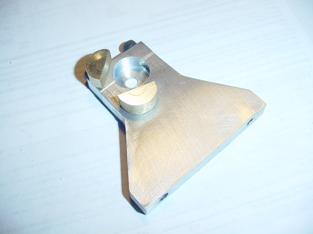
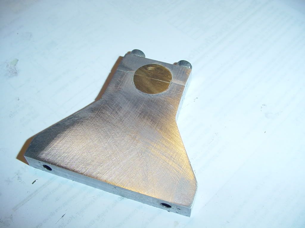
Tonight I made the split brass bushing for the center bearing stand. This is kind of a pain---you can't just make one bushing and saw it in half, because you lose the material from the sawcut. So--you make two bushings and mill half of each one away. After it was made, the two halves were loctited into the upper and lower section of the bearing support with Loctite 638, and the bolts liberally coated with grease and snugged up to clamp everything in place. I have this rather involved plan to make certain that the center bearing stand gets bored at the correct height to match the crank. When I drilled and reamed then all together in my rather questionable set-up, earlier, I hatched this plan. The outer two bearing stands, with roller bearings in place get bolted to the base, (crankshaft removed) and I will put a peice of 1/4" drill rod thru them. The drill rod is long enough to hold in the chuck in my mill by one end, while it is in the bearings. I will then use an angle plate to secure the base to the mill table, and make certain that there is no bind with everything firmly bolted in place. (turning spindle by hand, no power). When I am satisfied that my set-up is good, I will remove the drill rod and bolt the center bearing stand to the base. I will then drill and ream it in place. This should ensure that the bore thru the brass bushing is perfectly concentric to the inner diameter of the ball bearings.---I HOPE!!!
SPLITBUSHING001.jpg

SPLITBUSHING004.jpg

 
Brian, I am eager to see how this idea turns out. This has me on the edge of my seat!
 

Brian

The theory behind this seems good. As long as everything is secured firmly I see no reason why it will not work. I'll be watching for the results.

Cheers

Don
 
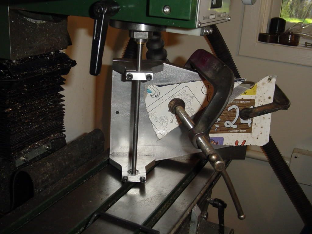
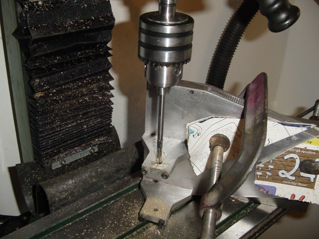
Here are a couple of pictures of the set-up I used to drill and ream the center bearing stand bushing. In one picture you see the drill rod thru both outer bearings and held in a collet in the mill spindle, with the base clamped to an angle plate which is bolted to the bed. In the other picture, I have changed out the collet and drill rod for a chuck, removed the top bearing stand, drilled the center stand, and reamed it. I then tore down the setup and bolted the outer bearing stand back into place. The shaft turns very freely, without binding, and is firmly supported in the outer two roller bearings that are inset into the stands, and in the center bushing.
FREEASABIRD001.jpg

FREEASABIRD003.jpg
 
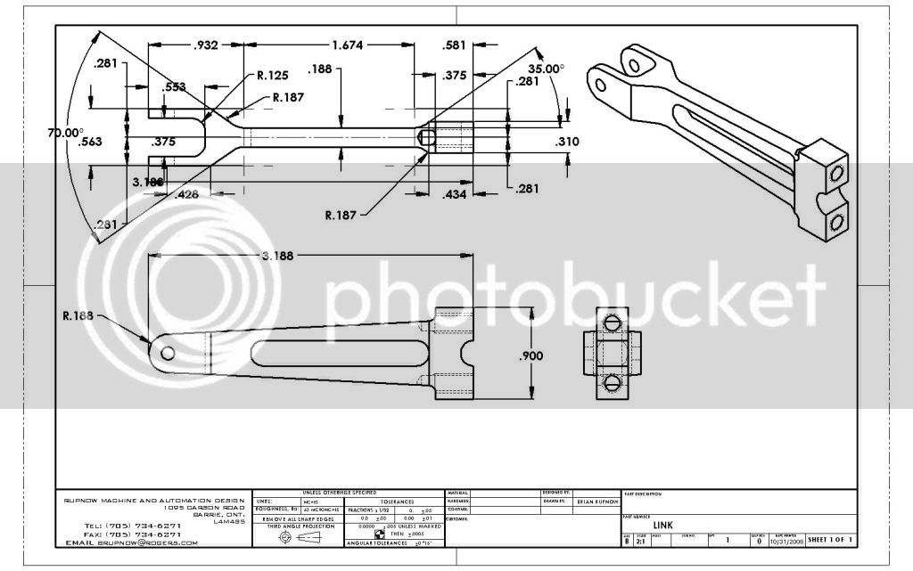
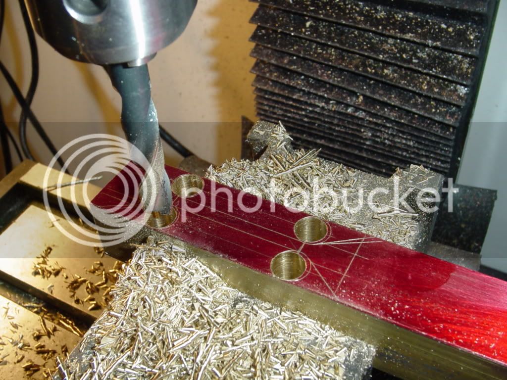
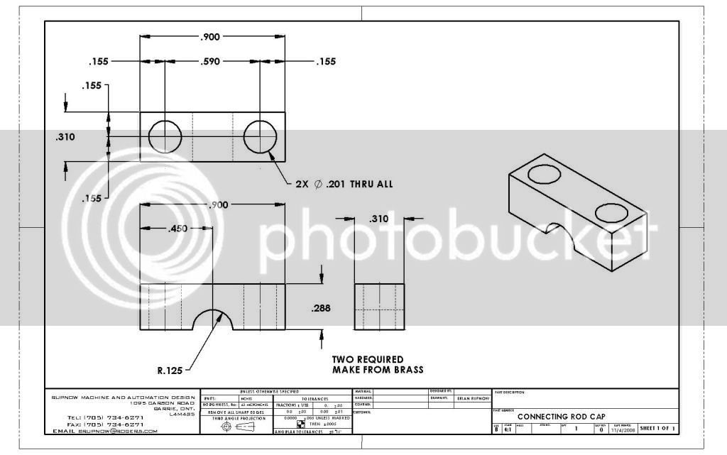
Tonight I started the brass connecting rods that attach to the crankshaft. The drawing is not finished, it just has enough info on it to get me started. When I design something in 3D, the drawings are generated automatically, but I still have to add in the dimensions--Since I have already input the math data when I created the 3D model, all I have to do is tell the computer which dimensions I want, and where to put them. So---this is "from the beginning"--first I create enough dimensions to get me started, then I lay out what I need to on the brass material, then its off to the mill.---More to follow---
link.jpg

CONNECTINGROD-1001.jpg
 
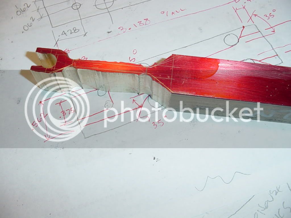
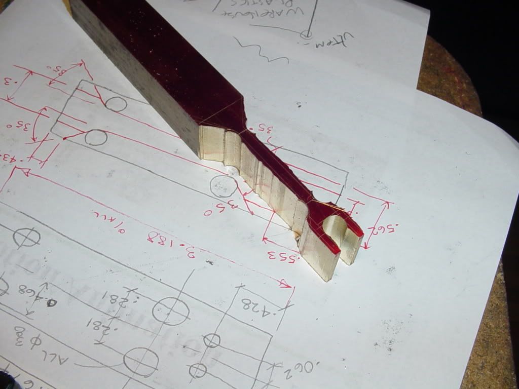
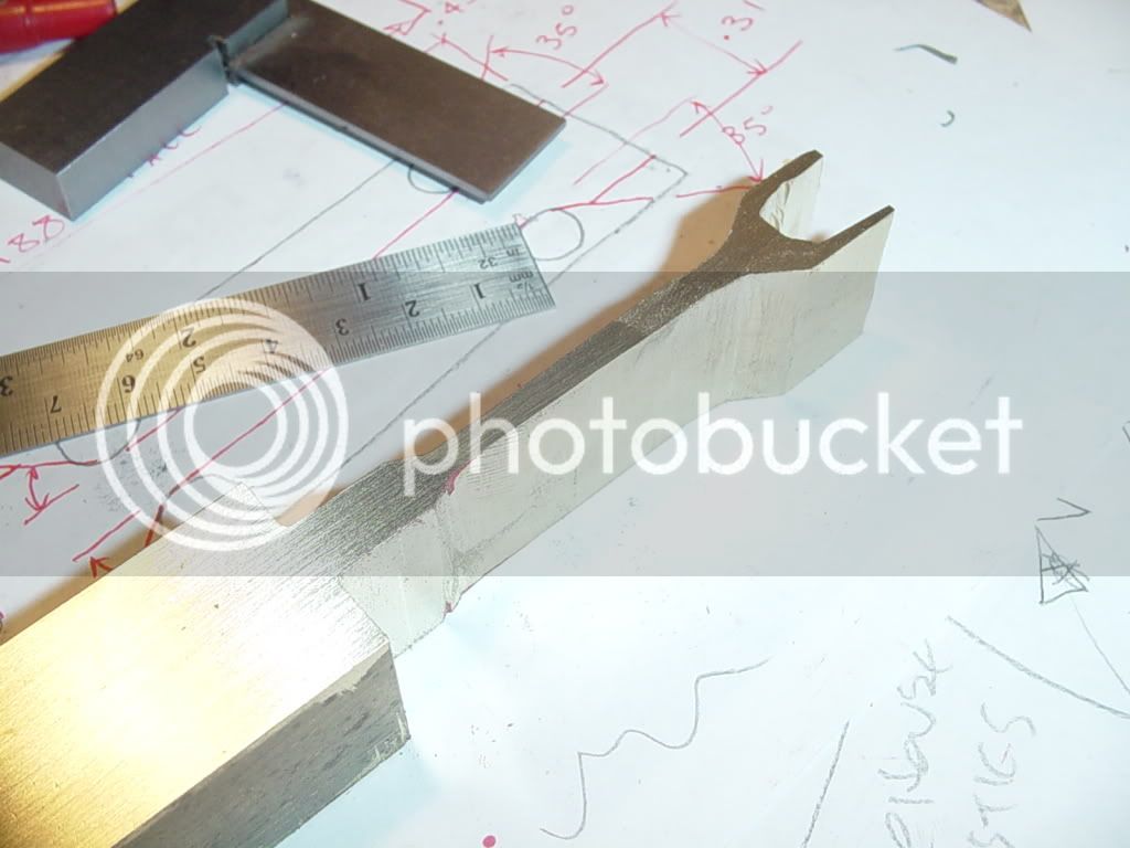
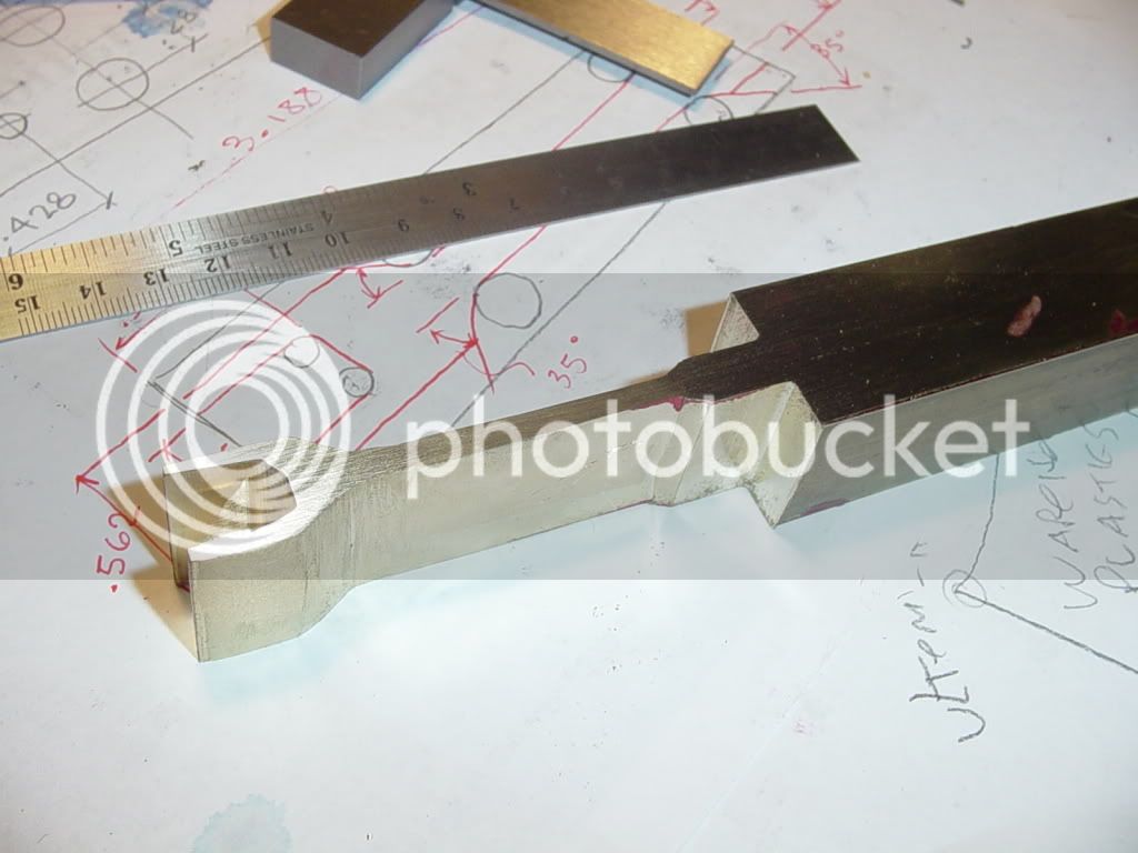
Conrod profile in one plane finished. Heck of a pile of work to get to this stage. Things shouls start to look interesting when I do the other profile.
CONROD-2002.jpg

CONROD-2001.jpg
 
Good show Brian! We should start a new forum....The Joys of Milling Con Rods Twice! :big: :big: :big: I like the profiling you've done.

Cheers,
Phil
 
Philjoe--I'm watching your engine devlop as I'm building mine. What great fun, and Lord, what a vast amount of time it takes! I am learning new skills every day, and really enjoying it. Even though I've been designing machinery for over 40 years, I am developing a whole new respect for the time it takes to make machine parts from scratch!!
 
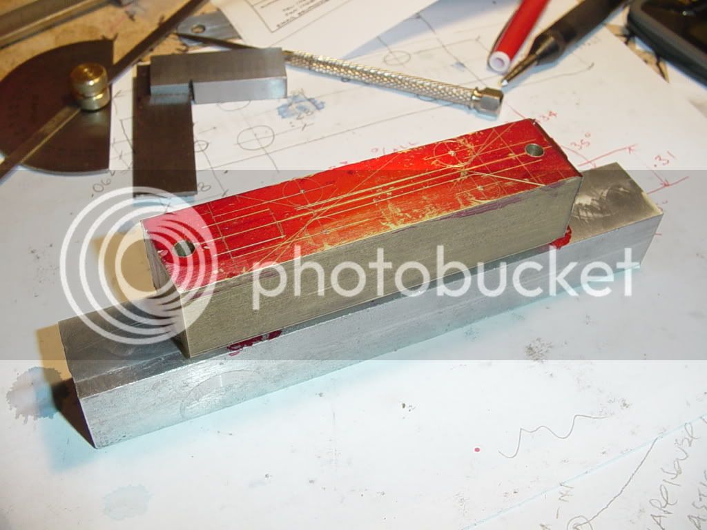
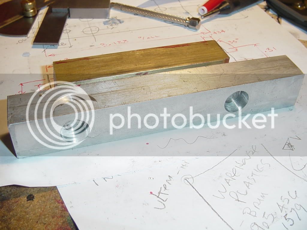
For my second connecting rod, I've had to resort to a different way of holding the peice of brass for machining. Brass is so expensive now that I bought "just enough" plus an inch more to make the con-rods. The first conrod went easy, because I had the other half of the 1" square brass bar to hold onto in my milling vice. For the second one, (where the material is only 1" longer than the con-rod, I have drilled and tapped both ends 1/4"-20 and matched the holes to two "on size" holes in a 1" square aluminum bar to give me something to hold onto. I placed three 1/4" flatwashers between the brass and the aluminum peices to allow the end of my milling cutter to clear the brass but not cut into the aluminum. I will let you know how this works when I am finished the second connecting rod.---Brian
CONROD-SETUP001.jpg

CONROD-SETUP002.jpg
 
Fixtures are great aren't they? They're the invisible tricks that solve a lot of problems. 8)

Cheers,
Phil
 
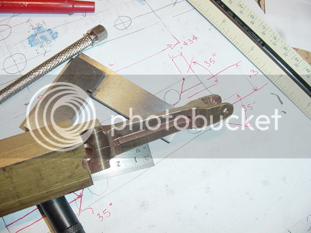
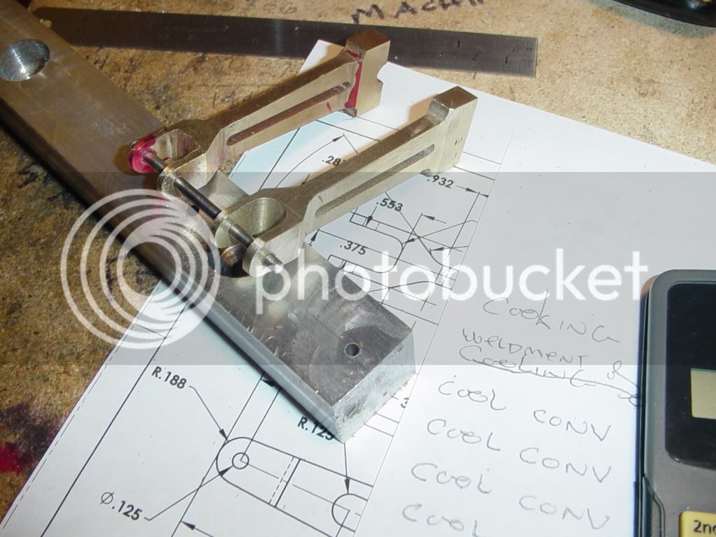
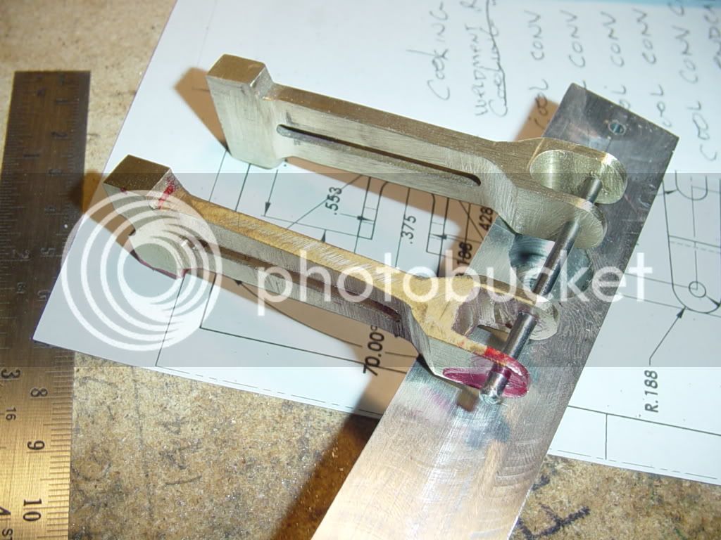
And now we have two---Good Lord, is it ever hard to make two identical peices. I still have a bit of creative file work to do, but the milling is done. You can see that in a fit of misguided enthusiasm I went ahead and put the 1/4" "half hole" in the crankshaft end of the first rod I built.-- wish I hadn't done that. I'll deal with it. What you can't see is the last two 1/8" diameter holes I drilled in the wrong place in the second part---And they were the last 2 holes required for the second major profile cut. Since I wasn't about to throw away a days machining, I made two 1/8" diameter brass plugs and silver soldered them into place, then moved the holes to the right place.---We live---We learn!!!!
CON-RODSTWO001.jpg

CON-RODSTWO002.jpg
 
Brian,

Thanks for your efforts and for including the pluses and minuses in you work :bow:

To make 2 identical anythings by hand is as you say difficult :eek:

Best Regards
Bob :D
 
Maryak said:
Brian,

Thanks for your efforts and for including the pluses and minuses in you work :bow:

To make 2 identical anythings by hand is as you say difficult :eek:

Best Regards
Bob :D
Maryak---Thanks for having a look and commenting. I am following your I.C.E. build with interest, but I think I have a ways to go to bring myself to your level of expertise.---brian
 
Brian its great watching this come together

as for identical parts i've only ever made identical stuff ups , i spend that much time doing what you call creative filing i'm making a filing machine before doing anything else

the only thing that matters is learning

oh and the ability to correct the stuff ups

thanks for the marking out tips , thats been excellent

gonna save me a heap of time very soon i hope

cheers

jack


Latest posts

Back
Top