Vertical 4 cycle engine from recycled parts

Home Model Engine Machinist Forum

Help Support Home Model Engine Machinist Forum:

This site may earn a commission from merchant affiliate links, including eBay, Amazon, and others.

Brian Rupnow

Design Engineer
Project of the Month Winner
Joined
May 23, 2008
Messages
14,978
Reaction score
8,270
Location
Barrie, Ontario, Canada
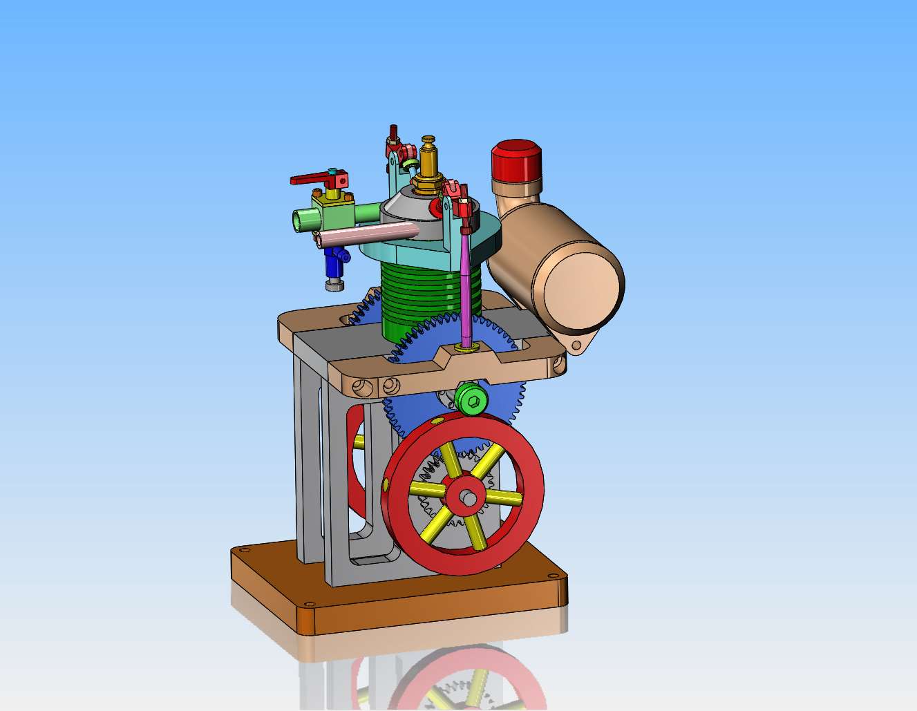
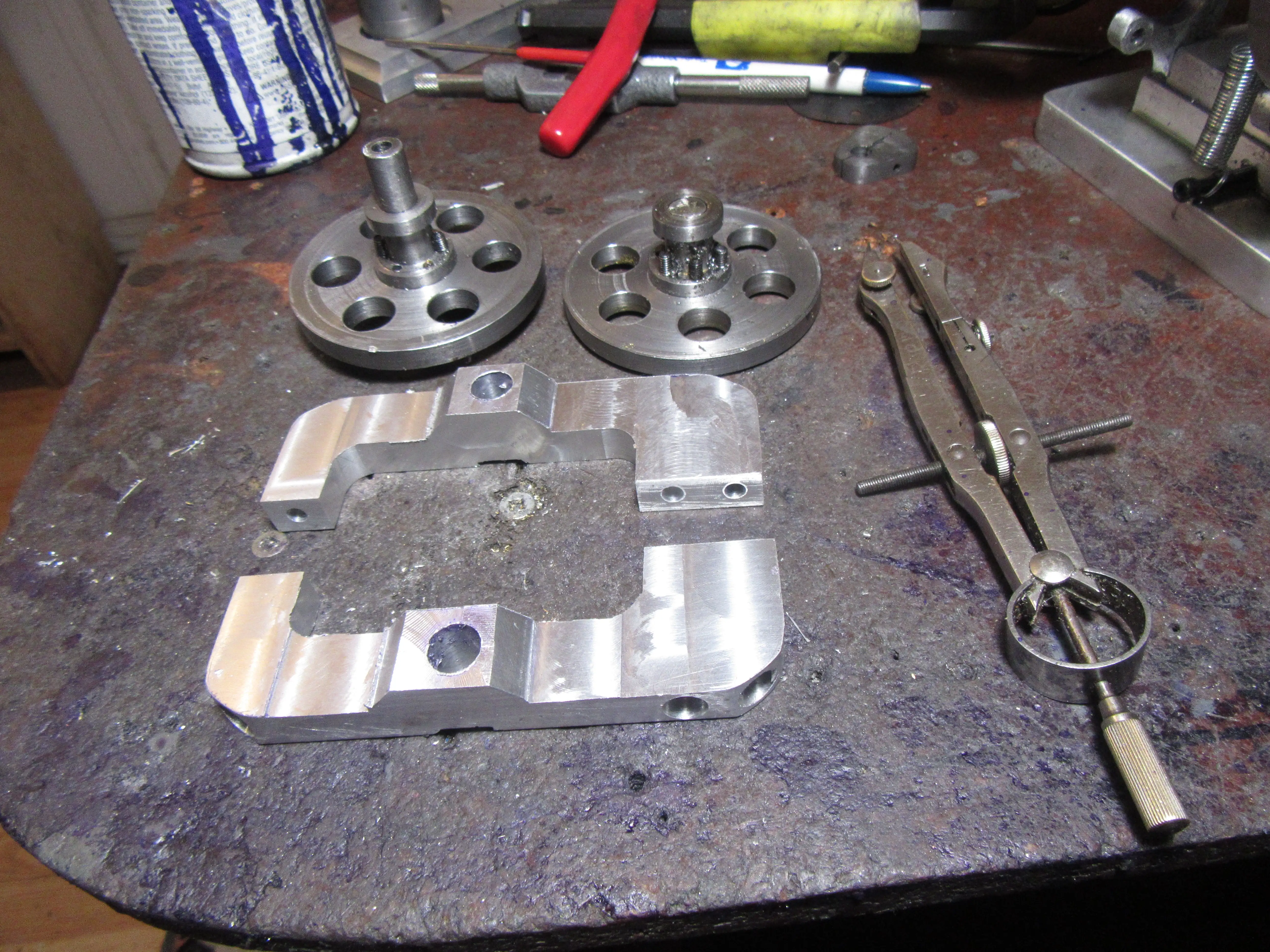
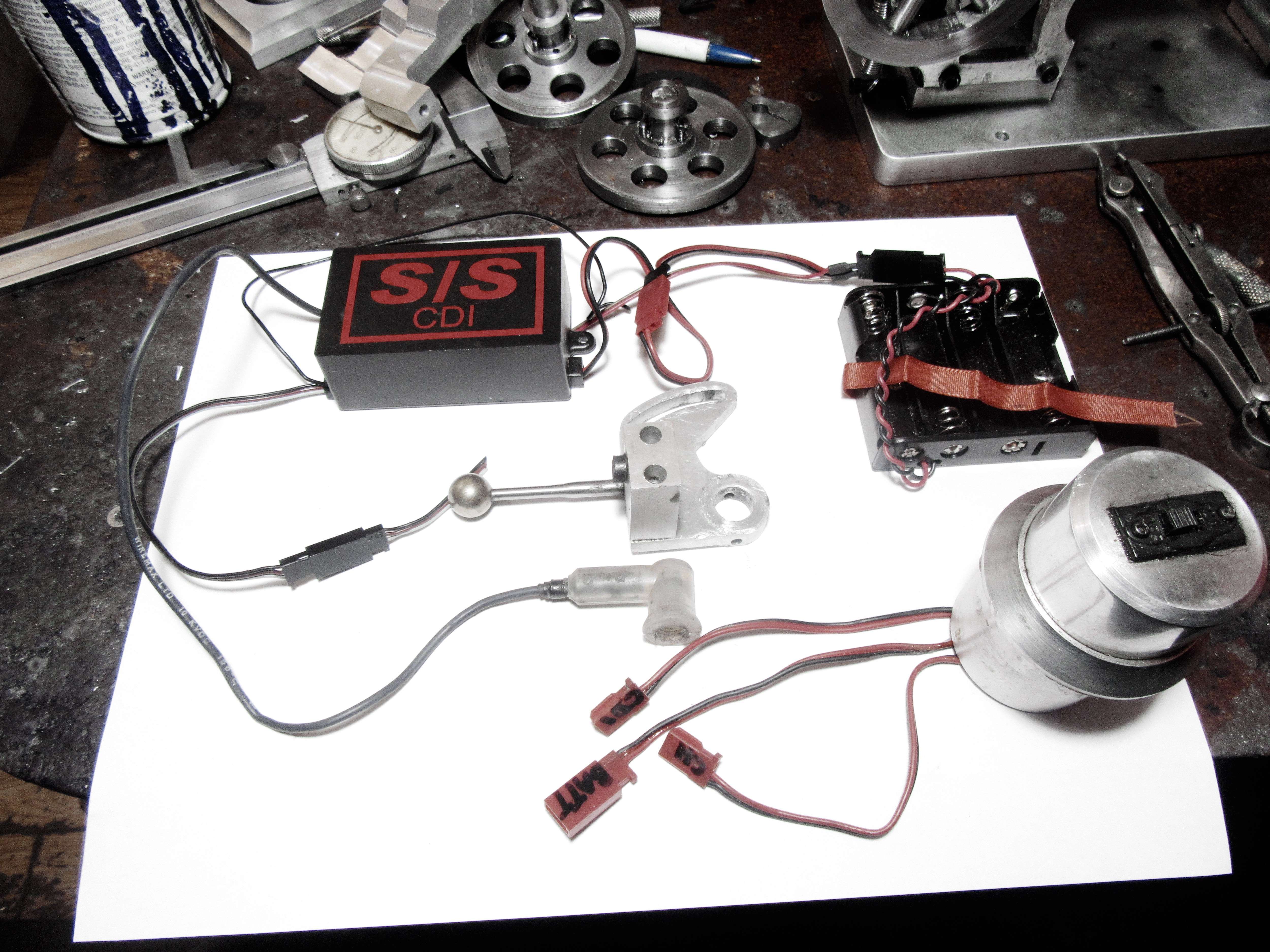
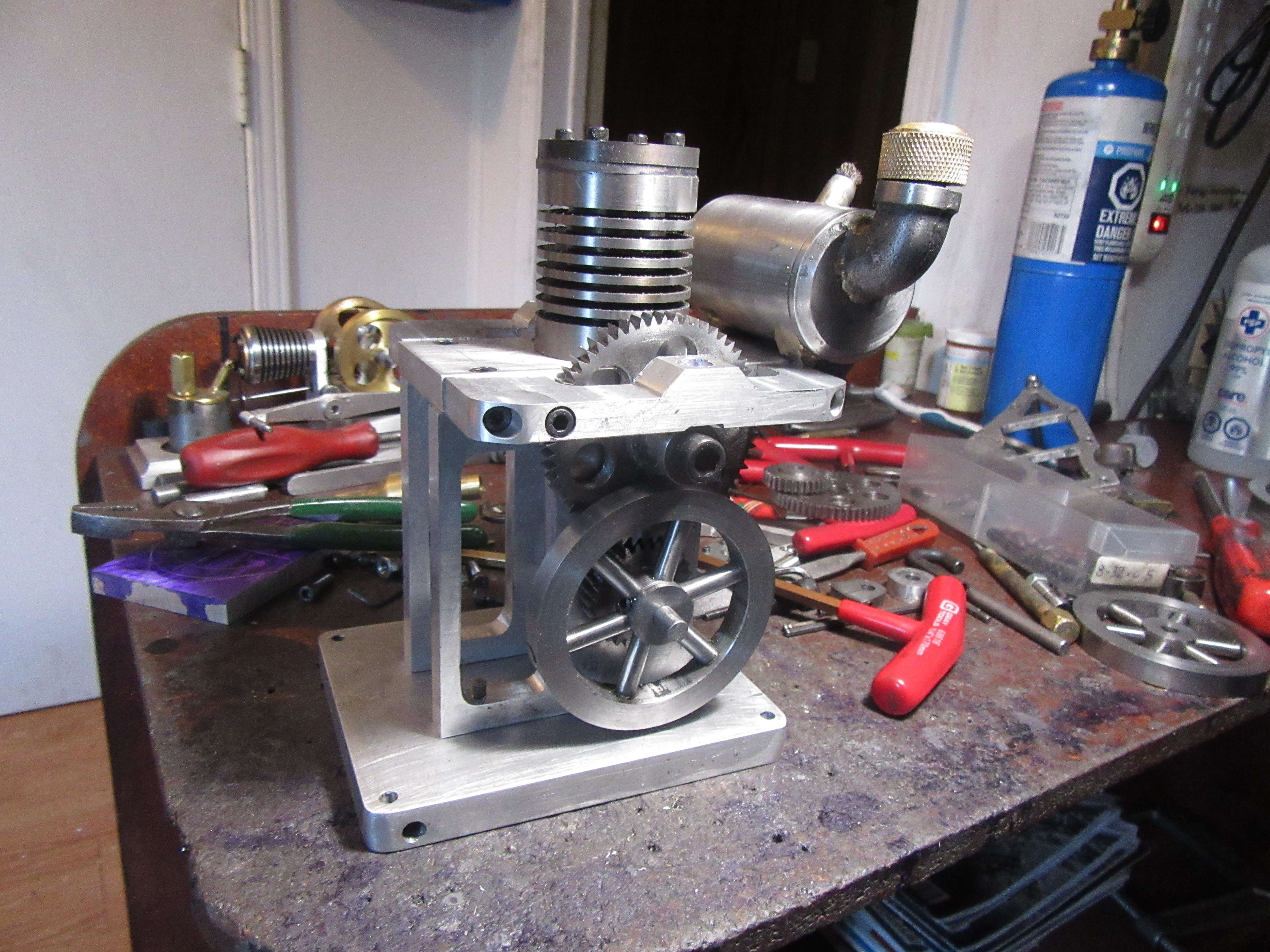
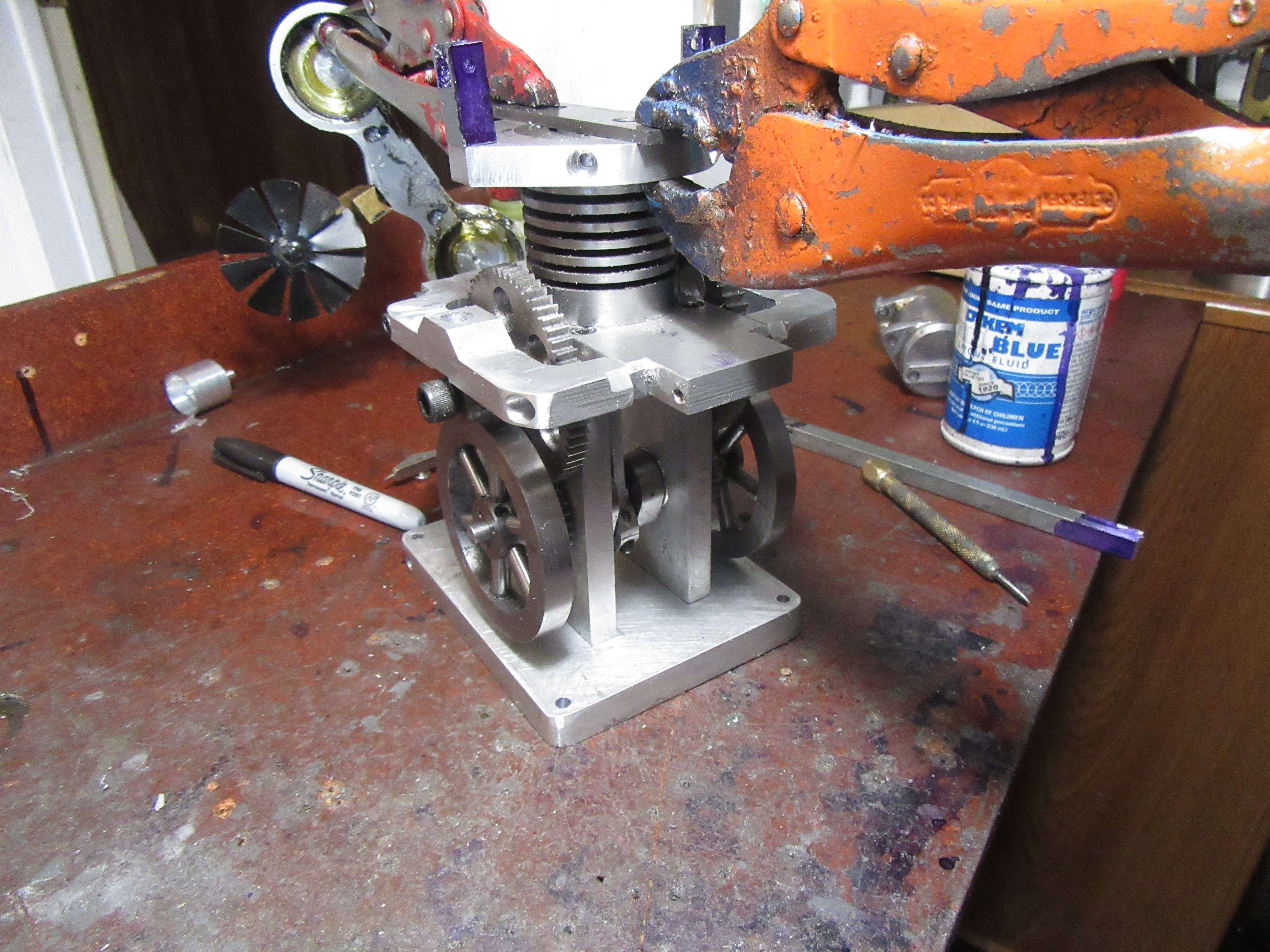
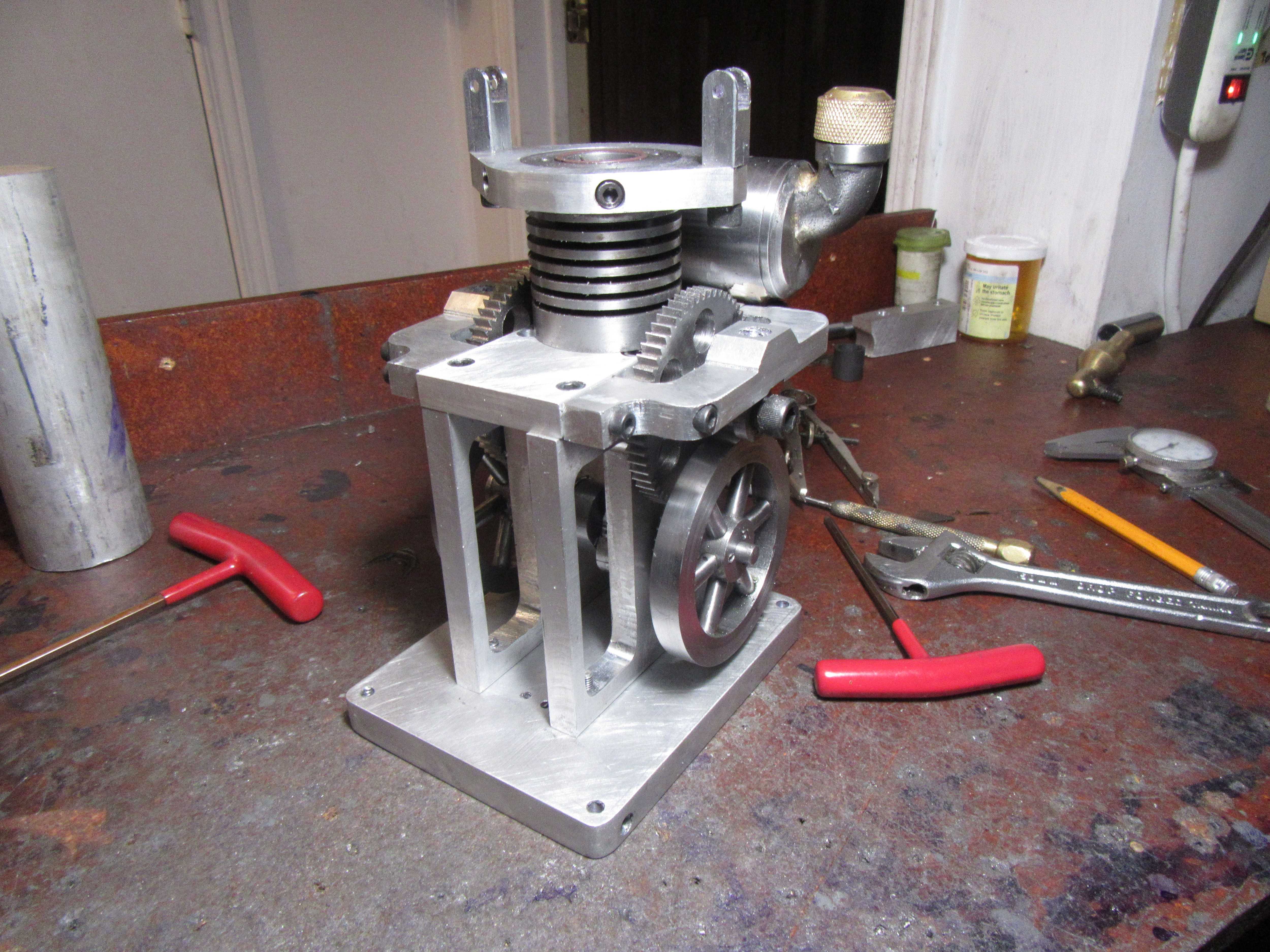
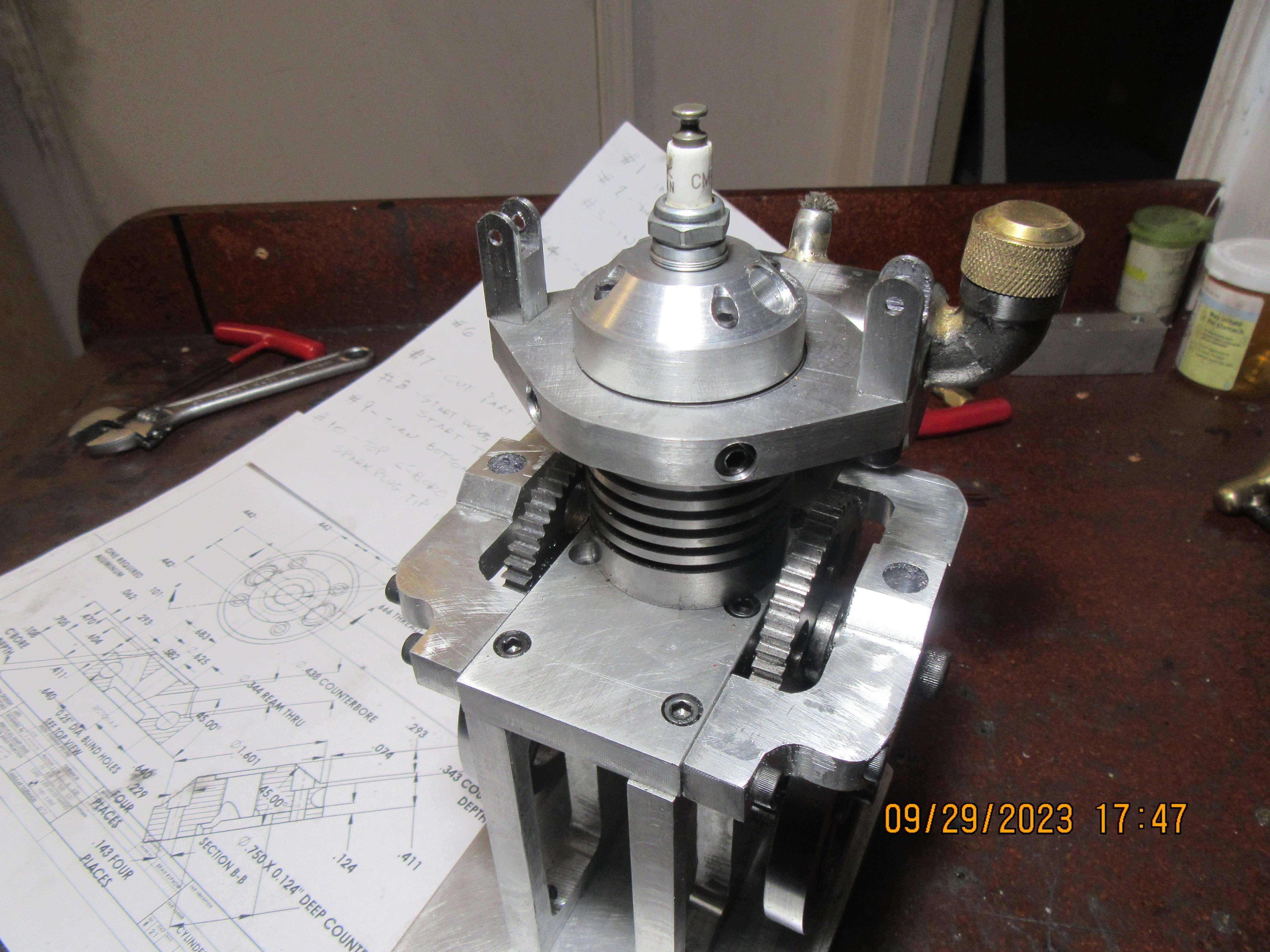
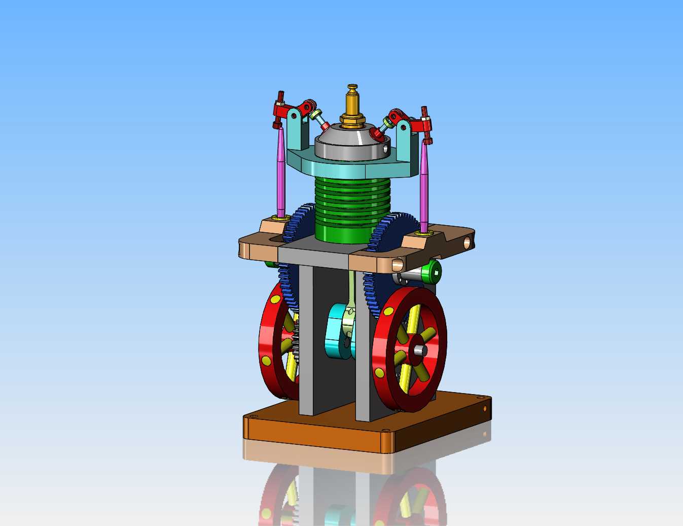
You have probably all seen by now that I tried to build a "cross beam flame licker" engine and failed to get it running. I made two different cams for it, and took advice from several well intentioned people, but it just wasn't going to run. I have spent a happy day at my computer, designing a new four cycle gas engine which will be built using almost all of the flame-licker parts without modification. Other than the sideplates and the smokestack, all of the other parts get a second chance at life. I haven't sussed out the intake and exhaust yet, but that will come tomorrow. I love a day when I can set at my computer, uninterrupted and design a new engine based mostly on parts that I already have. Will I build this engine?--Yeah, probably. The alcohol tank will get a repositioned fuel outlet and become a gas tank.
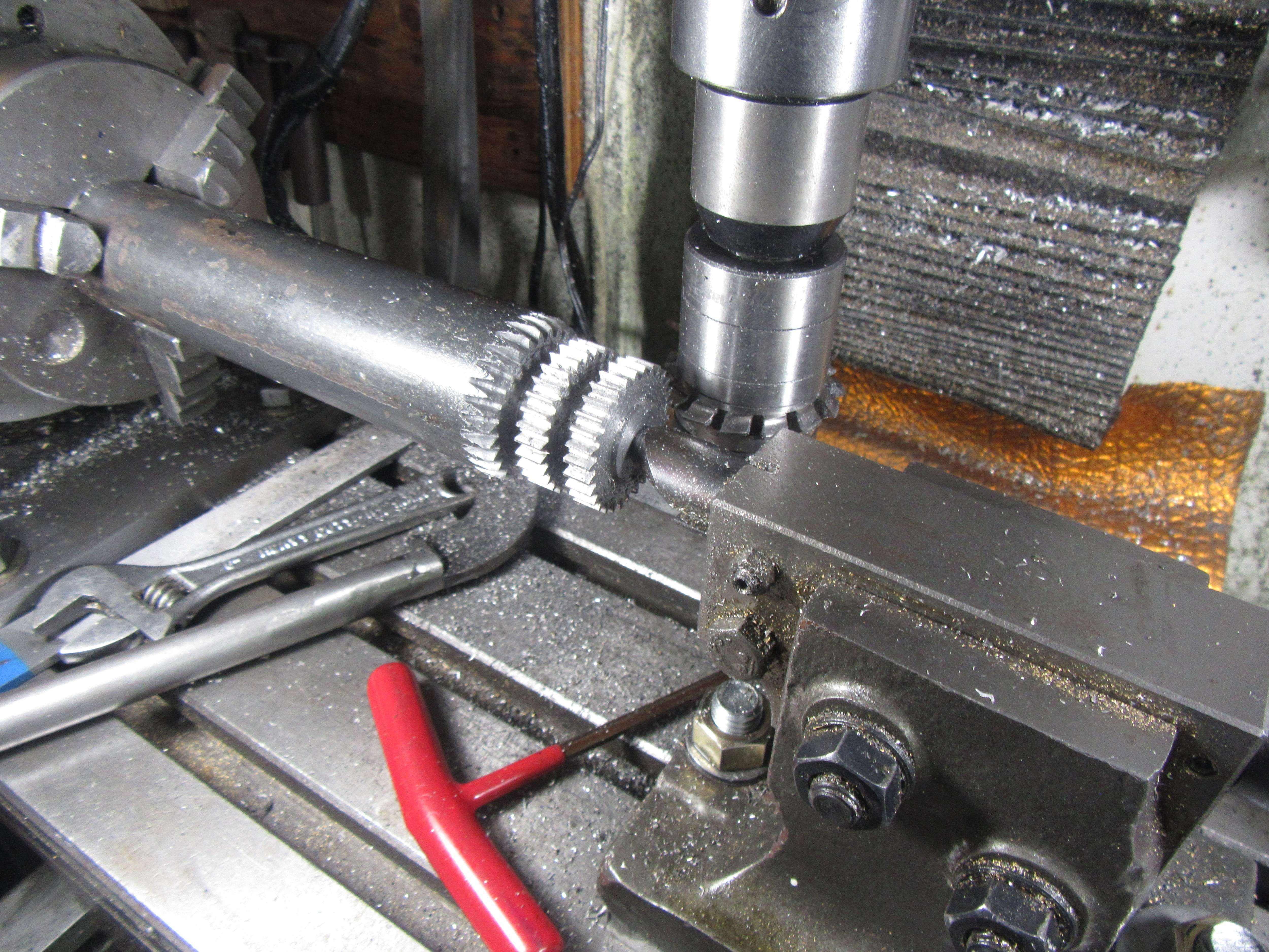
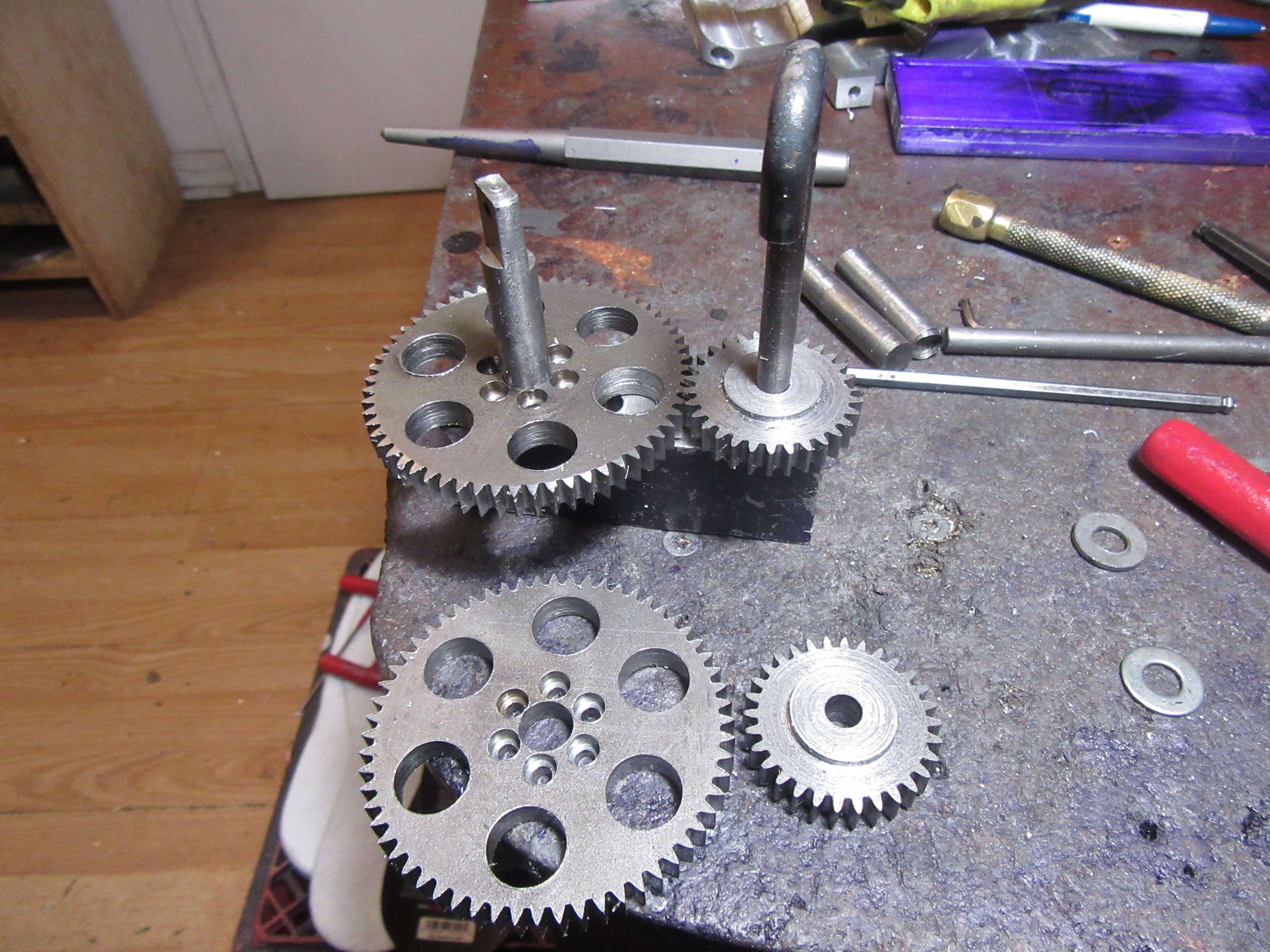
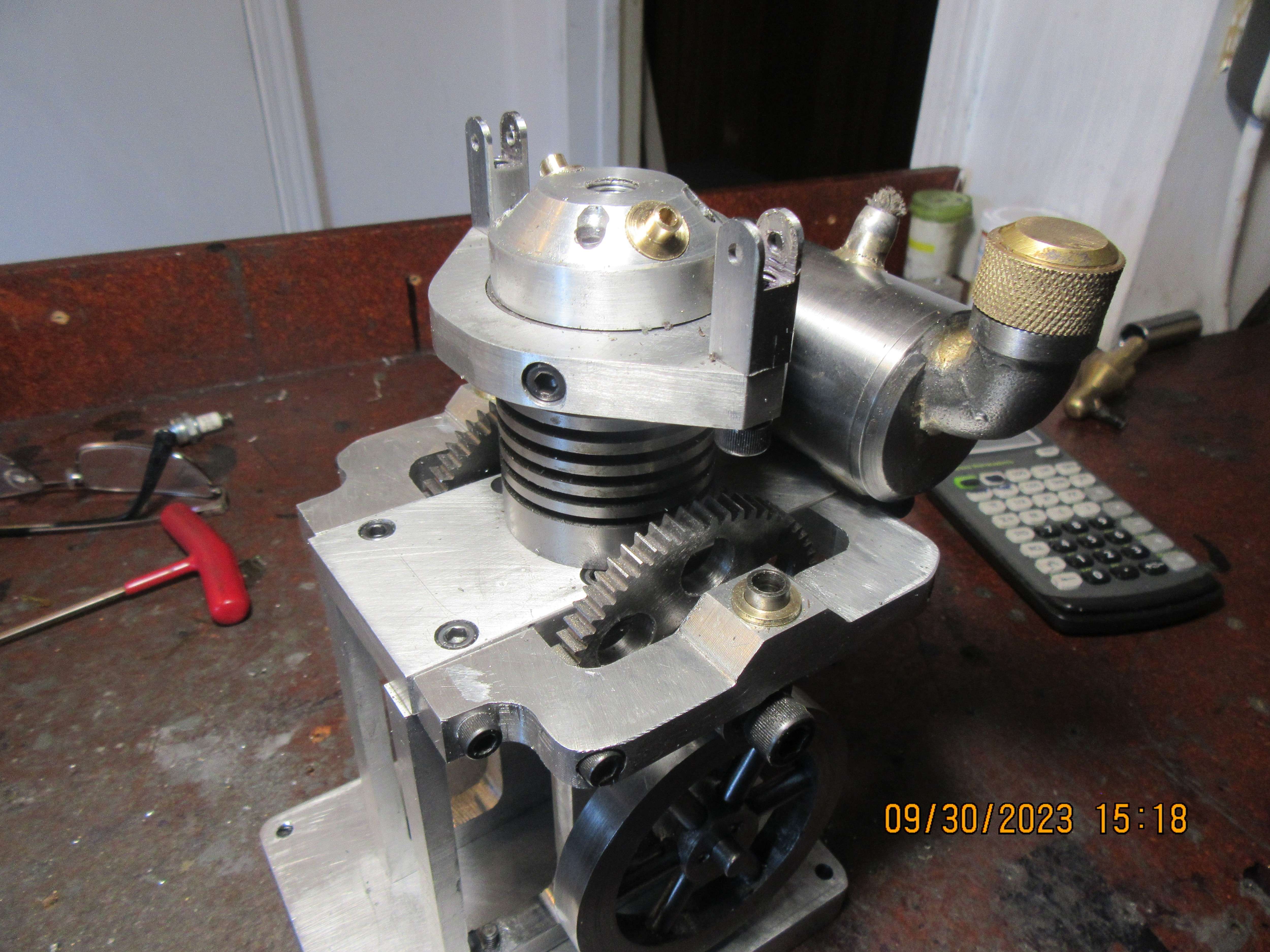
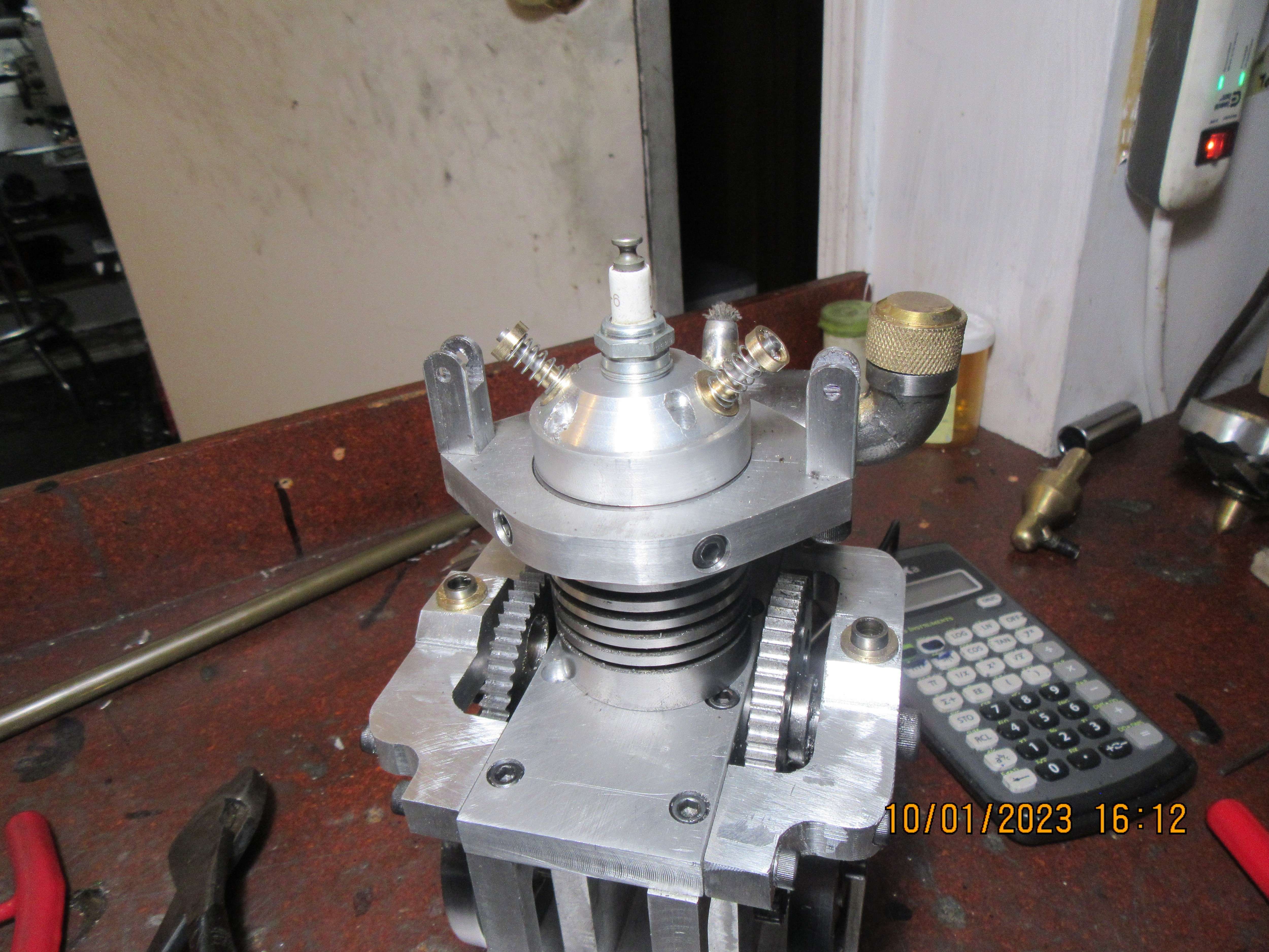
One interesting thing about this engine is that it doesn't really have a camshaft. In order to keep everything aligned vertically and not have the con rod passing thru the camshaft, I am running a double set of gears mounted on shoulder bolts.
JYNbbo.jpg
 
You could save a lot of work if youi had an atmospheric inlet, only one set of gears needed and you would have room to put a rocker post on the head and have the valve vertical. This would bring the pushrod closer to the cylinder and you may then be able to get the gears and cam behind the flywheel and save having to use such large gears.

Why did you not use the existing horizontal layout? if you just change the head to atmospheric inlet and have the exhaust valve operated by the beam you don't need to alter much just head and somr gears/cam

Third option would be to convert the flame licker into a single acting air engine. Just a head change to a simple piston valve that can be operated by the beam and simple cam. I did that on an engine that did not work out how I intended but it made a great air/steam engine. The red block on the far sid eof the engine was fitted over the flame port, air in from below and out the oily hole you can see. Piston valve horizontally just opens and closes inlet & exhaust

 
Last edited:
Posting that made me remember this video, with the flame lickers and sterling engines you need minimal friction, this is how long the flywheel turns without the conrod or valve rod attached, you should have been getting similar with the flame licker.

 
This morning I finished up the design, and I like it. I particularly like the new cylinder head. It is almost impossible to get a 10mm thread sparkplug and two normal sized valves into a 3/4" bore cylinder head. Having the valves at an angle lets me accomplish that. I have re-used the alcohol tank as a fuel tank, with a couple of minor changes.
1Pyh46.jpg
 
Last edited:
There is a little trick in making multiple gears. If you prepare the gear blank properly, you can cut two identical gears at a time. All it means is that every time you feed the blank thru the gear cutter, you have to feed it a little farther. You end up with a gear twice as thick as one gear would be plus the thickness of your parting off tool.
 
I spent yesterday and today making up gear blanks for the large timing gears, the stub-shafts which bolt to the large gears, and the two top plates. The stub shafts will have a cam cut on the end which is not bolted to the gear. There is almost a whole days work in those two top plates which are right and left hand.
1hsgxY.jpg
 
About 15 years ago I built the original "Rupnow Engine" and I used a complete CDI system from S & S Engineering for my ignition. The "Rupnow Engine" has been cannibalized over the years, giving up parts to build other engines, but I saved all (or most) of the CDI system. I hope to use this system on the new engine, but I had to send off an email to Roy Scholl this morning and ask him, "What am I lacking ". I think I only need a magnet and a sensor. I've been using old Chrysler points, coil, and condensers an all of my engines, but I think this new engine will be easier to adapt to the electronic ignition.
1v6KTq.jpg
 
Werowance---Nothing so sophisticated. The gear blank is a flat plate bolted to the extended cam part. You are looking at the ends of the bolts. They are all trimmed off now.---Brian
 
I always feel so good when my gears are cut, and they actually mesh when installed on the correct centers. I don't make that many gear sets in a year, and although I've written all the "How to's" in a book for my reference, I still get a big pucker on until the gears are finished.
5zNdtA.jpg
 
Today was spent finishing a bunch of plate work and bolting everything together for a "trial assembly". Everything fits, and I'm quite happy with it at this stage of the game. There is going to be a lot of fussy-work in the new cylinder head. I've been in touch with Roy Scholl trying to get figured out what I need for ignition on this engine. The old original "Rupnow Engine" from 15 years ago has been disassembled and I saved all of the electrical parts that I had originally bought from Roy when he ran S & S Engineering.
zTZpO2.jpg
 
I've been working away in the background. My internet has been out for 30 hours and just came back on. Somebody dug up one of the main optic fiber cables and cut it in two with a back hoe.--Bad ju-ju for somebody. My gears mesh properly. On one side they meshed perfectly--the other side required a bit of "file and curse" work, but they mesh fine now. The top plate which holds the rocker arms is dummied up into place, but I haven't tapped the cylinder for it yet.--It gets a bit complicated---I drill the holes and counterbores in the plate, Loctite it into place and let the Loctite dry, then use a transfer punch thru the holes to mark the cylinder where it has to be threaded. I've had some moments of doubt about this build, but its not costing me anything, and it's giving me something to do.
NtlN4W.jpg
 
Today I got some time to finish up the rocker arm support plate and drill and tap the cylinder to attach it. Also finished and bolted on the vertical supports that the rocker arms pivot it. I think the next parts I make will be the cylinder head and valves. I want to have them finished and in place before I do the rocker arms.
CRiZe2.jpg
 
Today I machined the new cylinder head. There are so many set ups required to build this cylinder head that I had to make a list of operations before I started machining it. I'm happy with the way it turned out. None of the steps were terribly difficult---it's just that there were so many of them.
j0NU9n.jpg
 
Today I machined the valve cages and tappet guides from what I believe was bronze (that big bunch of material I bought a few months ago has both brass and bronze stock in it, and I can't tell the difference by sight).--It machined like bronze. I also machined the tappets from 01 steel, and they will be flame hardened before being put into actual service.
qjcXZ7.jpg
 
Today I finished the valves and valve retainers, and hunted thru my box of 1000 springs to find something close to what I wanted. Those springs might be a bit too light, but I'll know better when I try and start this engine.
g3OjSl.jpg
 

Latest posts

Back
Top