Horizontal Double acting Twin Self starter

Home Model Engine Machinist Forum

Help Support Home Model Engine Machinist Forum:

This site may earn a commission from merchant affiliate links, including eBay, Amazon, and others.
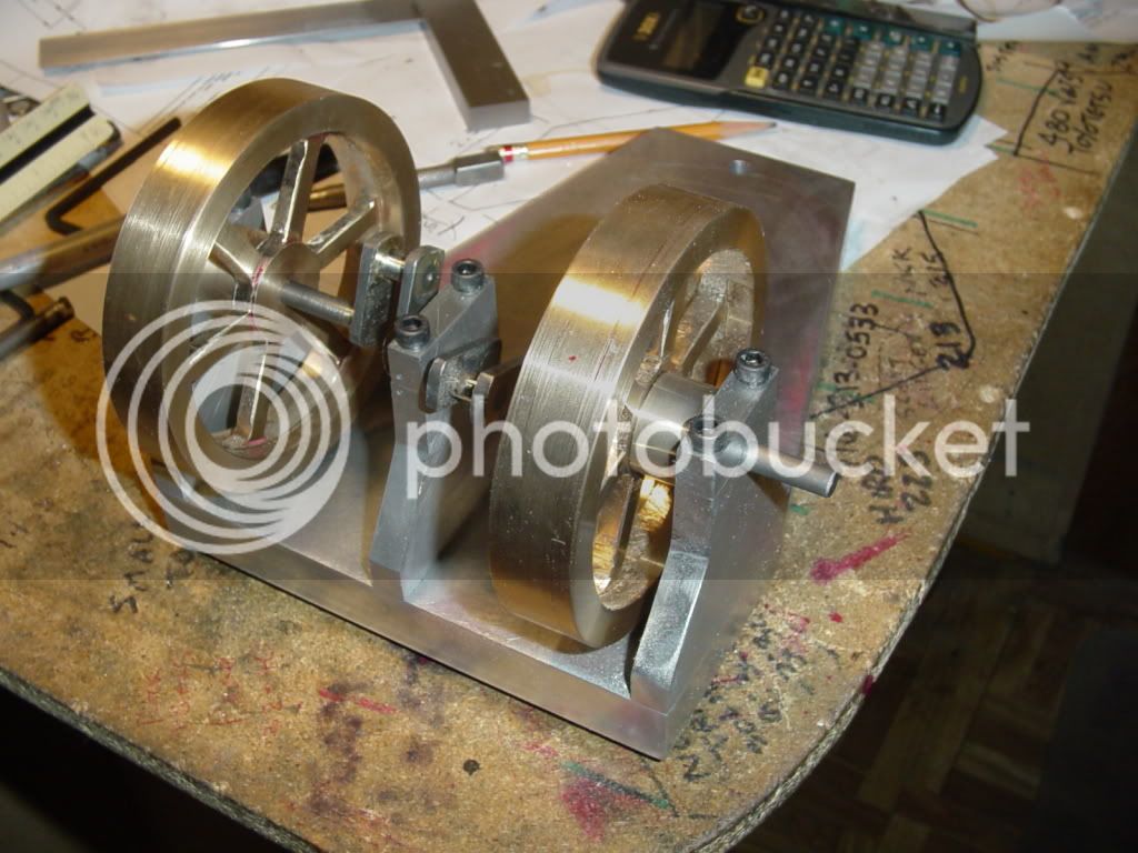
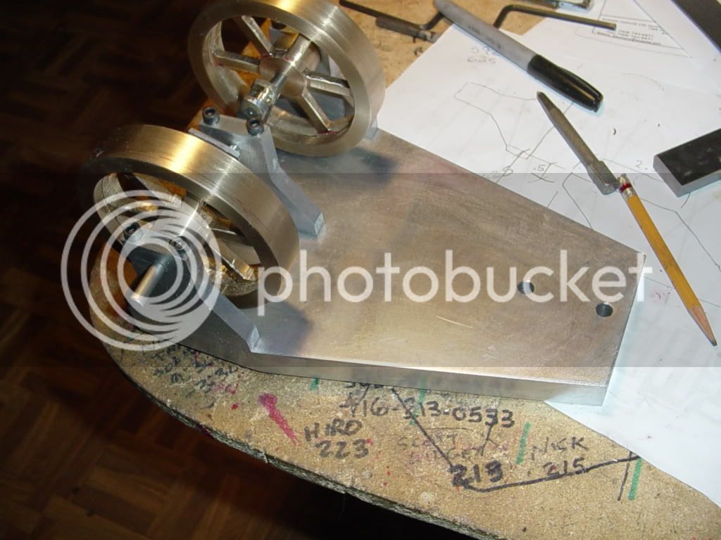
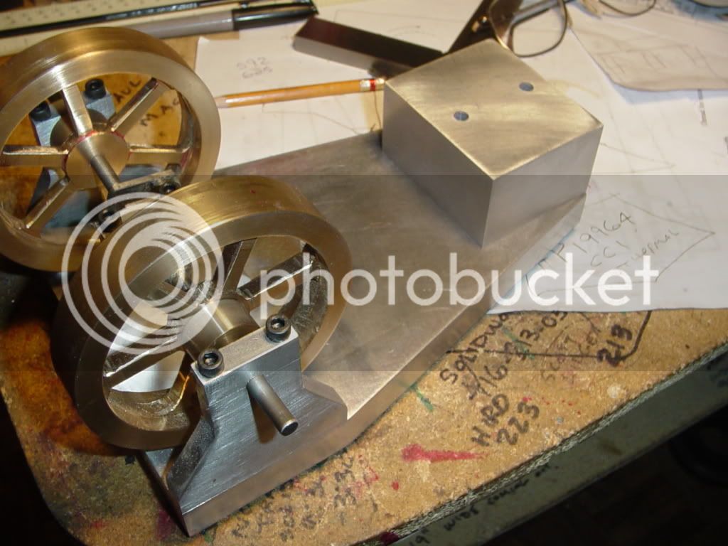
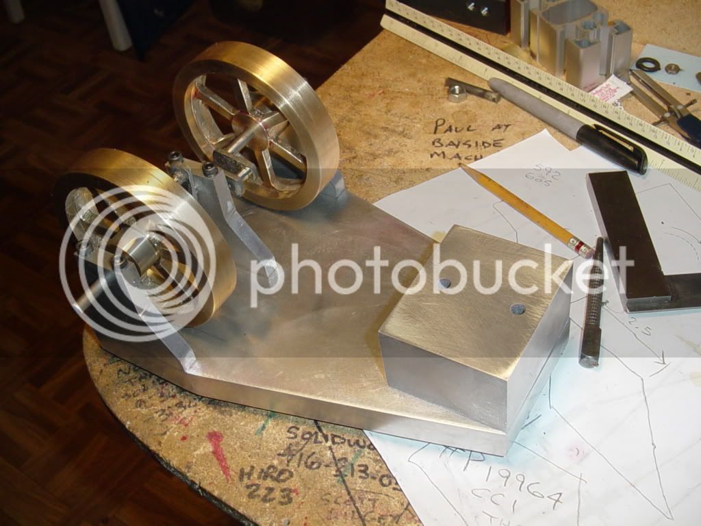
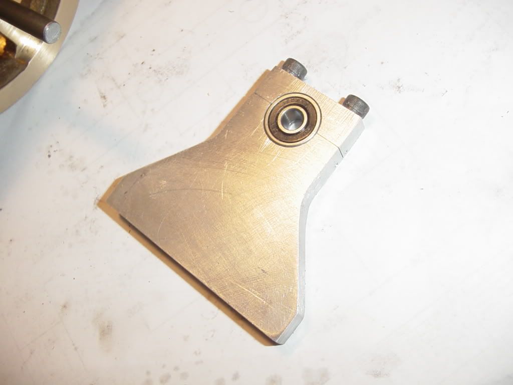
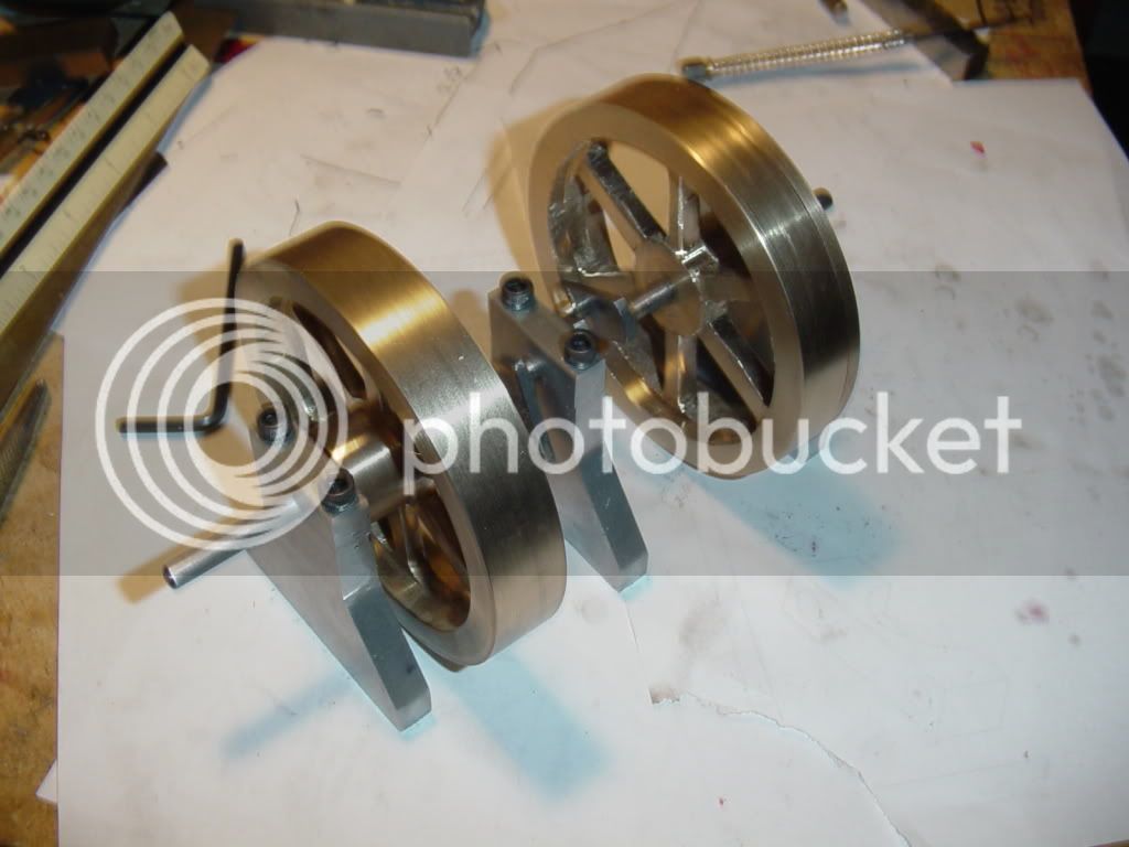
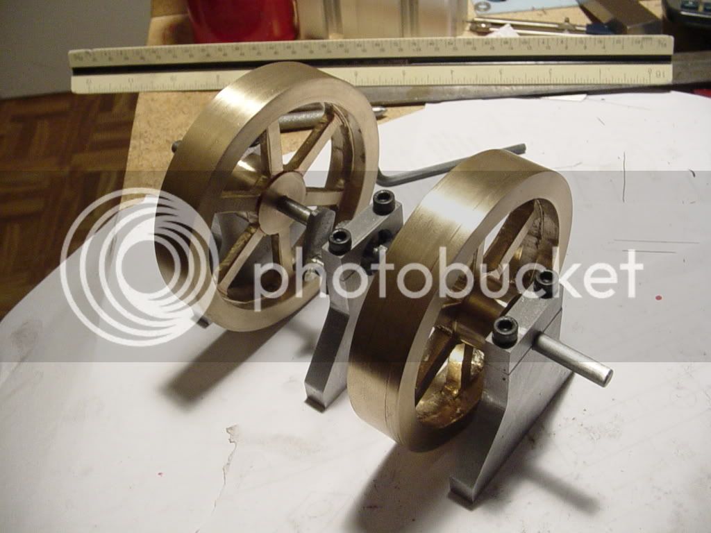
Well, thats enough for me for one Saturday. I'm tuckered out!! For all who worried about my setup---Each bearing stand was bolted to the aluminum plate with 2 bolts. The aluminum plate was clamped to the angle with two c-clamps, and the angle was bolted to the mill table with two 10MM bolts and T-nuts. Nothing moved, nor tried to move. Thank you for your concern. You are probably right about something under the cantilevered bearing stands being a good idea, and if they had been steel I definitly would have had additional bracing.
BRGSTANDSCOMPLETE004.jpg

BRGSTANDSCOMPLETE003.jpg

BRGSTANDSCOMPLETE001.jpg
 
Glad it's all worked out fine Brian .......... looks like a very nice result 8)

OK ............. what's next ......... never mind this "having a rest" stuff ;D

CC
 
Brian Rupnow said:
Kludge--I used the old tried and true "magic eyeball" method of determining 90 degrees---that and a small layout square. I didn't solder them both at the same time. I soldered one, let it cool, then lined the other one up and soldered it.

Ah, okay. Thanks. This means I can end my frantic search for a side thread while imagineering a jig in the process. :)

This is quite an education for me, Brian. Many thanks for letting us watch over your shoulder.

BEst regards,

Kludge
 
Kludge---Have you ever heard about "Don't follow me---I'm lost!!!!" I'm not sure that I advocate doing things exactly as I'm doing them. There is a lot of this stuff that I am posting that I have never done before, except in books and on a computer. Most of the time I'm making it up as I go along. :big: :big: :big:---Brian
 
Brian Rupnow said:
Most of the time I'm making it up as I go along.

Yep, but that's the part that's so educational! It's in part the actual means used but also an implicit guide to how you got there. I've mentioned before about your ability to think on your feet and this is a prime example.

BEst regards,

Kludge
 
Since I now have the material, and I'm worried about knocking the finished parts off the corner of my desk where they currently reside, I think I may make this part tomorrow. Just a word of caution---when I post a drawing up here, please be aware that it is a preliminary drawing, meaning that I will build to that drawing unless I find some reason not to. This is a very good example---If you go back to the first or second post where the overall General arrangement of this project is shown, you will see that it is designed with a 1/2" baseplate. this morning as I was pawing thru the "Shorts Rack" at my local metal supplier, I found a peice of 6" x 3/4" x about 16" long, so I have changed the plans to have a 3/4" thick base. When I get all the way through this build, I will place an updated set of drawings in the download section.---Brian
basefordoublehorizontal.jpg

 
Brian, everything is looking great! In my opinion, you are doing a terrific job both on the design as well as the build.

Regarding the previous setup on the bearing blocks; I echo the thoughts of the others. I leave it there as there is no point in riding a dead horse. ;)
 
Its early Sunday morning here. I get up and play (quietly) in my little machine shop and on the computer untill wife and daughter get up. This morning I flycut the surface on one side of that peice of 6" x 3/4" flatbar that I picked up for a base. No--flatbar isn't really flat. It always has a crown on one side, a depression on the other. My flycutter uses a tool with a carbide insert, and although I can say with due certainty that the bar is now flat, (at least on the side I will be bolting my peices to), the surface finish leaves much to be desired. I have the remedy for that---a peice of emery cloth in my orbital sander. Problem is, its an air powered orbital sander (from my body and paint era) and the great big air compressor is in the garage---right under wife's bedroom!!!! So---I'll not be doing any more work untill wifey pops out of bed and declares that she is ready to face a new day!!!
 
Brian Rupnow said:
So---I'll not be doing any more work untill wifey pops out of bed and declares that she is ready to face a new day!!!

;D :D ;D ............. Wise move

CC
 
So--Wife is up and about. The peice of flatbar has been flycut on one side to be perfectly flat, then sanded with a peice of medium grit emery cloth in my orbital sander to remove most of the machining marks, then coated with layout dye. I started to cut it out on my bandsaw, but that was taking forever, so it was out to my ancient tablesaw with a woodcutting carbide tipped blade. I put a bit of "blade wax" on both sides of the blade, then cut 3/4" aluminum just like it was a peice of wood. It cuts very well, and clean, but is terribly noisy and if your not really hanging on to the aluminum with a death grip it will "kick back" and knock your head off.--Definitly a time for leather gloves and a full face shield!!! You also get showered with chips, but it sure do cut fast. You can see that I cut about 1/16" outside the actual "cut lines". These will be finished in the mill.
BASEROUGHEDOUT001.jpg

BASEROUGHEDOUT002.jpg
 
I've also cut aluminum up to 1/2" thick on my table saw. It feels like a very scary operation, so I don't do it very often. Ear protection is definitely a good idea in addition to the leather gloves.

Chuck
 
Well, thats it for today. Everything fits, and it looks like I had planned. There is a bit of minor binding on the shaft, but nothing that a little tweaking won't fix. I am amazed at how freely the shaft and flywheels spin with the ball bearings I am using. The center stand will be a split bushing. I have to pick up a couple of counterbore tools this week. I believe I have a purchase order coming through on Monday to design a heat treat furnace, so this project will probably slow down for 3 or 4 weeks. Last week I had no "real work" so was able to devote every day to playing "Mr. Machinist". ---Then again, I'll probably just work more in the evenings to see it finished.
BASEFINISHED001.jpg

BASEFINISHED003.jpg

 
Brian looking very very good

glad they spin as hoped

happy your getting paid work in too getting paid to design a heat treat furnace
cool!

i've made a few myself but no real design to them besides the controls for the gas jets

glad its all comiing together for you

the wheels the stand and the base all look excellent

cheers to ya

jack
 
Jack---Its not a heat treat furnace (Ya, I know, I said it was).--A local company manufactures heating elements, and after they are welded together, they have to go through an induction coil that heats them red hot --(actually its an anealing furnace).--then they run thru a nitrogen cooling loop thats supposed to cool them down to 100 degrees F. Trouble is, it only cools them to 500 degrees, and they are literally "too hot to handle". I am going to design some transfer conveyors with open mesh belts and large cooling fans to pump air over them and accumulate them on a picking table so that they are cool enough for people to pick them up and move them for more processing. This will involve some pneumatic automation to grip them and pull them out of the furnace, a roller conveyor, some "flippers"--(Think pinball machine), and an 8 foot long, 22 foot wide open mesh belt conveyor and a couple of huge fans. Pretty standard stuff, but still time consuming design wise.
 
Brian Rupnow said:
Jack---Its not a heat treat furnace, they have to go through an induction coil that heats them red hot
( edited a heap )

Brian will send you a PM

magic words Induction coil!!!! not for modeling but will PM you may have another job for you if you know induction technologies

cheers
 
Congrats on the progress Brian!

This is the first thread I go to every time I log on.
I want to see this animal breathing as much, if not more than you do!

Rick
 
Brian Rupnow ..... so it was out to my ancient table saw with a woodcutting carbide tipped blade. I put a bit of "blade wax" on both sides of the blade said:
If you must cut it on a table saw you would do best to clamp it to a guide or piece of wood so you can get a good grip so you do not have to use gloves they are a recipe for missing fingers around any machinery.
Regards,
Gerald
 
This morning while waiting for my Purchase Order to come through, I machined and mounted the riser block that sets between the base and the cylinder block. No magic here--just a lot of bandsawing, flycutting, and filing to get rid of flycutter marks. The purchase order came thru at 11;30 so I'm of and running on a new design job for the next month. Damn, I like money!!!
RISERBLOCKMOUNTED001.jpg

RISERBLOCKMOUNTED002.jpg
 
I phoned my favourite money pit today and ordered up some brass. I have pretty well made up all the aluminum bits that are required, and I don't want to machine the eccentrics untill I have the brass rod ends made. I don't have a 3/4" reamer, so I use a (shudder) 3/4" drill to put the hole in the brass end, then machine the steel eccentric to fit.
 
Brian, it is looking fantastic! I am glad the rotating assembly rotates easily. ;) That just goes to show you are spot on in your measurements and machining.

As the others have said, I'm watching this build with a lot of envy and enthusiasm!
 
Back
Top