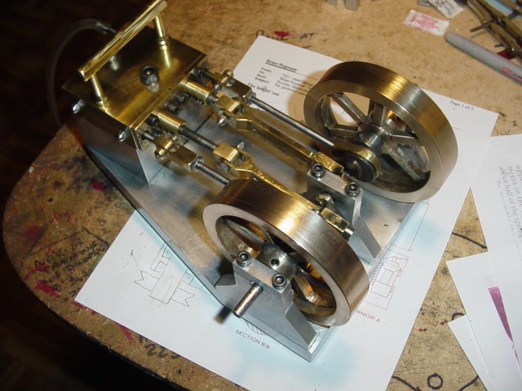
Horizontal Double acting Twin Self starter

Home Model Engine Machinist Forum

Help Support Home Model Engine Machinist Forum:

This site may earn a commission from merchant affiliate links, including eBay, Amazon, and others.
kvom said:
Very nice job, and fast!

I hope you don't burn out at this rate ;D
Kvom--Burn Out??? Me??? Well, yes, the last week has been pretty intense. I enjoyed the thrash, but I'm glad its mostly over, and that the engine runs as well as it does. I've got a bunch of little stuff to clean up and finish off right, but the "big rush" is done, and I'm glad of it. Things are slow in my real business right now. This damned economic thing has really put the brakes on any new machine development, and since about 85 percent of industry in Ontario seems to be driven by the automotive sector, and its hurting in a big way, I may have nothing to do except frig around with steam engines untill things pick up a bit.
 
I don't know what I can add that hasn't already been said other than the degree to which I am impressed by the design and how you went through the build. That includes explaining all the steps including recovery from the "That wasn't supposed to happen!" parts which are no less educational.

Okay, now I have to find the Taig!

Best regards,

Kludge
 
I spent the last couple of days finishing things off properly. The port plugs in the sides of the cylinder block were finished off with stainless steel acorn nuts, the temporary wrist pins were replaced by custom made bolts with brass nuts, and I created a brass log type manifold. Most things that could be easily removed were taken to the polishing bench given a bit of polishing. I now consider the engine to be truly finished, and I am happy to take a break for a while. I have about 10 hours run time on the engine now, and it will set and quietly tick over on about 12 pounds of air pressure. It won't self start on such a low pressure--It likes to see about 20 PSI to self start, but thats just the difference in static and dynamic friction.
FINISHEDANDBLINGED001.jpg
 
Brian,
A great looking engine. Congratulations on designing and building a fabulous engine. Any chance you'll ever show in the US? If so, let us know :bow: :bow: :bow:

Cheers,
Phil

 
I am currently working on designing a flyball governor to put on this engine. (or any engine of compareable size) Things are preliminary right now, but if you want to have a look, its over on the other thread I have going about flyball governors.--Brian
 
Brian,
Well Done!!
That is a good looking engine. I am looking forward to seeing what you do with the flyball governor.

Gerry a.k.a. oldboatguy
 
Someone pointed out to me today (Aug-15-2010) that the drawing packge I have had available for download has an error on the cylinder drawing. I have corrected that drawing and added a few details of the intake manifold. These are zipped up in a zip file called Winrar. If you can't open it, Winrar is a free download from the internet.
http://www.mediafire.com/file/1gwo30e1be3tf5k/DOUBLE HORIZONTAL.rar
 
Hi brian got your drgs thanks and need to read this thread.Question how can i access this thread quickly without searching everytime
Can i instill a shortcut ???
 
Hi brian got your drgs thanks and need to read this thread.Question how can i access this thread quickly without searching everytime
Can i instill a shortcut ???

Now that you have commented on the thread it will be at the top of the "work in progress" section.
 
Thanks Nicolas,and thanks Brian for the additional info.Nice to know
that it needs 20 ibs to self start and about 12 to run.For when i finish it and
hopefully get it running Regards barry
 
This is a very old thread that has been resurrected. Since there seems to be renewed interest in it, I have been asked a few questions. The download link in post #213 has the corrected cylinder drawing in it. The cylinder drawing on post #133 of this thread can no longer be edited by me, but it is not correct. The download link on post #209 is dead. I see that I have not included the intake manifold drawings in the drawing package. The two 1/4"-20 tapped holes in the top of the cylinder block are the air inlets. Refer to my actual pictures and you will see that I have two threaded "nipples" that screw into the 1/4"-20 ports and are connected by a hollow 3/8" o.d. tube with capped ends. The capped tube has a 0.170" diameter "spigot" with a 0.080" diameter hole through it soldered into the pipe connecting the two "nipples". Air (or steam) is supplied to that 0.170" diameter "spigot" and then flows both ways down the connecting tube and thru the two nipples screwed into the 1/4"-20 threaded ports.----Brian
 
Last edited:
I have just remodeled the entire engine, based on the pdf files, because I had lost all the solid models in a computer crash a few years ago. I noticed that in the drawing downloads that I had never put in any drawings of the intake manifold system, and had not shown the port plug bolts nor the main cylinder block hold down bolts, so I have added them to the model. And yes, before anybody asks, assembly of the manifold is a rather amazing stunt. The two vertical pieces of tube with wrench flats on them are screwed into the cylinder block and tightened down. The primary air inlet, the cross tube, and the end plugs are soldered together as a unit. Then the top ends of the vertical intake tubes are coated with Loctite and the soldered manifold assembly is set in place over the vertical pieces of tubing with the wrench flats on them.--Crazy, but it works fine!!
 
Back
Top