Horizontal Double acting Twin Self starter

Home Model Engine Machinist Forum

Help Support Home Model Engine Machinist Forum:

This site may earn a commission from merchant affiliate links, including eBay, Amazon, and others.
Here we have the 4 peices of aluminum stacked and fastened with "crazy glue" , and the top peice coated with layout dye, and layed out.
brgstandsinprocess001.jpg
 
And here we have the peices up on the mill and two 3/4" holes drilled in the appropriate place to give me a 3/8" inside radius as the drawing calls for. You can see the "sacrificial" peice of aluminum closest to the mill table. HOWEVER--I just could not bring myself to trust the crazy glue. So---I drilled and reamed thru in 2 places and inserted 1/8" steel alignment pins. This was a wise idea. Later in the development of these peices, after the pins were removed, all 4 peices "fell apart".--so much for "crazy glue"!!! Won't use it again.
brgstandsinprocess002.jpg

brgstandsinprocess003.jpg
 
The peices have been almost completely profiled, and I opted to sawcut the 2 non-critical sides and fininsh them up with a file---much quicker and easier than another 2 mill set-ups. I cut both sides "almost" thru, because once these cuts are all the way thru, the peices will come apart. Before the cuts were completed, I layed out the holes in the top and bottoms of the peices. I can drill them and tap them as seperate entities, but I wanted to do the layout lines while they were still together.
brgstandsinprocess004.jpg

brgstandsinprocess005.jpg
 
The pins are a good idea but don't give up on the crazy glue, I use it like that all the time. Just make sure the parts are smooth and clean. :)
 
TaDa!!! We have 3 bearing stands that are identical. ONE POINT--before I seperated the 3 peices completely, I but a sngle centerpunch mark on the bottom of each peice at one end.--Why--well because again, we get into that centerline thing. Although I TRY to make the peices perfectly symetrical about the centerline, they never actually turn out that way. They are always out by a few thou one way or the other. By adding a centerpunch mark where it won't show, this lets me line all 3 peices up exactly as they were machined, to do any farther work on them.---And that "farther work" will be covered in my next post--adding a bearing cap and putting in the holes for shaft clearance and the counterbores to hold the bearings.
brgstandsinprocess006.jpg

brgstandsinprocess007.jpg
 
G'day Brian

this has been great to watch

maybe i can help with the "whittlin"

because its alu and a lot softer than steel which i normally work with

you may like to try something I use

Blind reamers

they are not hard to make and can be shaped to anything you want

Gunsmiths use them often and for specific jobs give them specific names but they are all blind reamers

a blind reamer is one that is used where the metal being reamed has a hole at the end that is not reamed to hold the peice steady

i'll up load a how to make PDF to the download section.


and again, am watching this with great interest ;D ;D ;D


Hi Brian,
If you are cutting dry the material will heat up and cause the crazy glue to release. Any time I held material together with crazy glue I used flood coolant, and never had any problems.
 
steamboatmodel said:
Hi Brian,
If you are cutting dry the material will heat up and cause the crazy glue to release. Any time I held material together with crazy glue I used flood coolant, and never had any problems.
I don't have a flood coolant option on my mill, but thats okay. I have discovered over the course of my 62 years on this planet, that adhesives, in general do not work for me. For one thing, I never have the time to wait for them to set up. If I am going to do something, then I want to do it RIGHT NOW!!! None of this "glue now and come back in 4 hours stuff". Other than Elmers wood glue, (on wood) and 2 part 5 minute epoxy on anything that isn't wood, I stay away from adhesives as much as I can. This latest crazy glue fiasco only confirms what I thought already--"If its machinery, use a metal fastener".
 
Jack404--Thank you for the interest and for the uploaded .pdf on making reamers. I just purchased an indexable boring head for my mill, (that I am anxious to try out) and I have a set of carbide boring tools that have never been used. My intent is to drill and ream the small "through hole" in the end stands, then use a 1/2" end mill to plunge cut the 1/4" recess that the ball bearing fits into, and then use one of my carbide boring tools in the indexable boring head to open the recess out to the required .687" diameter.---Note that I will be bolting the bearing caps onto the bearing stands before doing this.
 
Brian
All I can say is the stuff works perfectly fine, here. Nice clean flat surfaces, a good solid vise and yes... dowel Pins when it is practical. I think from here on.... I'll just silently observe.

Steve
 
Must be a Northern Hemiflat thing then Steve, 'cos it sure don't work too well in my Oz workshop
 
shelac disolved in methalated spirit was always called the watchmakers chuck. I still use it to glue
very thin brass sheet onto faceplates for cutting washers or wheel trims. Super glue is fine for mending cuts and broken crockery but its far too brittle once hard to stand the shocks of cutting. The heat wont help it but the impact from ythe cutter tooth will damage the bond.
If your trying to glue a stack of aluminum plates together for machining id use clamps instead. On the bits shown in the photos
a center clamp and two side clamps would have done the job.
 
Brian Rupnow said:
And here is the second soldering, set up in the jig. If it looks messy and ugly on your monitor, thats because it is messy and ugly. However, it will be going for beuaty treatment shortly.

Okay, there's a step I missed somewhere. How did you ensure the throws were 90o apart or did I miss a separate thread somewhere?

No, I'm not this far behind; it was a sudden flash of "Huh?" that hit me somewhere along the line.

Best regards,

Kludge
 
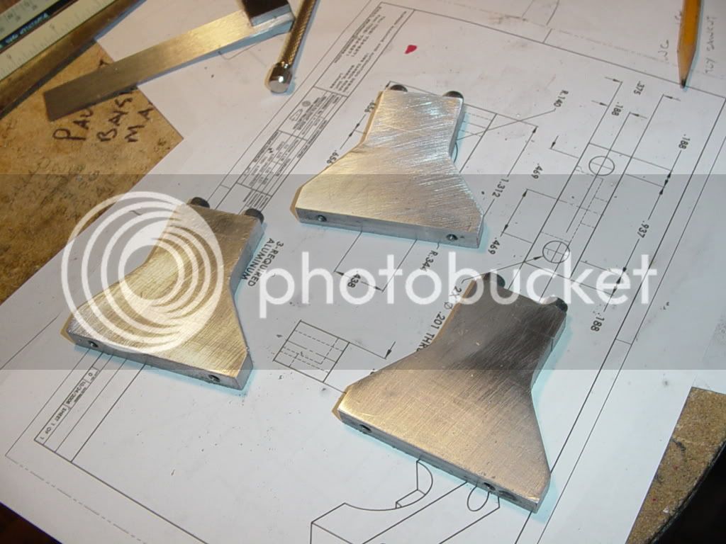
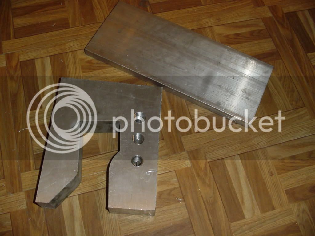
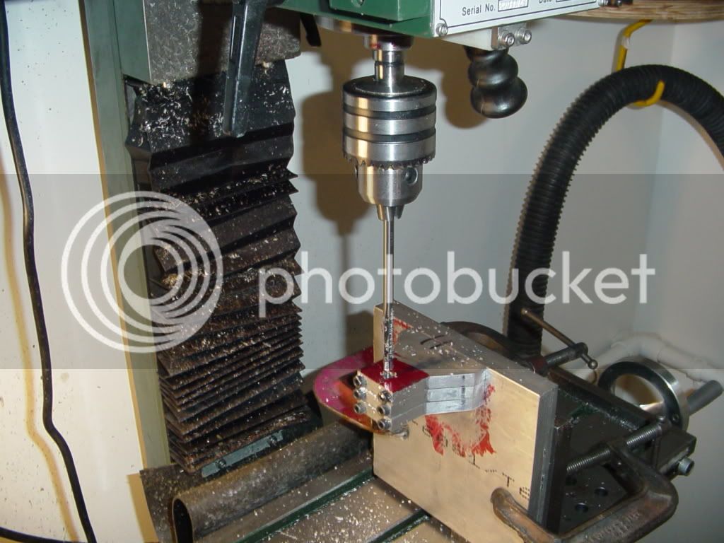
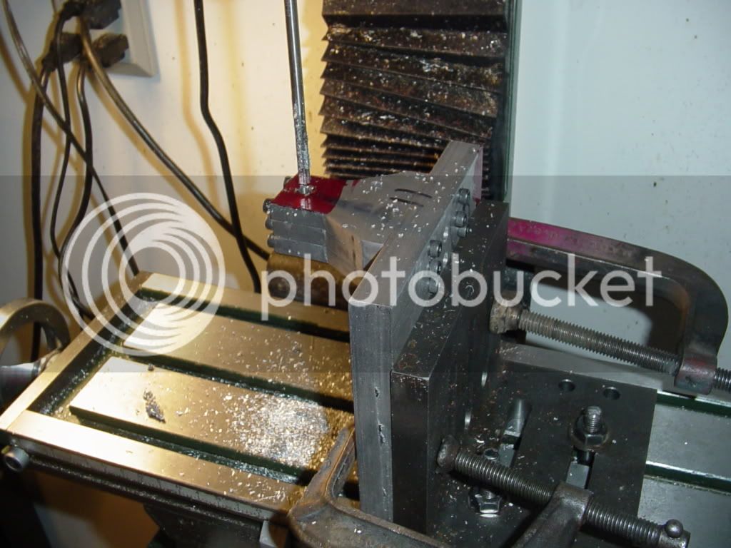
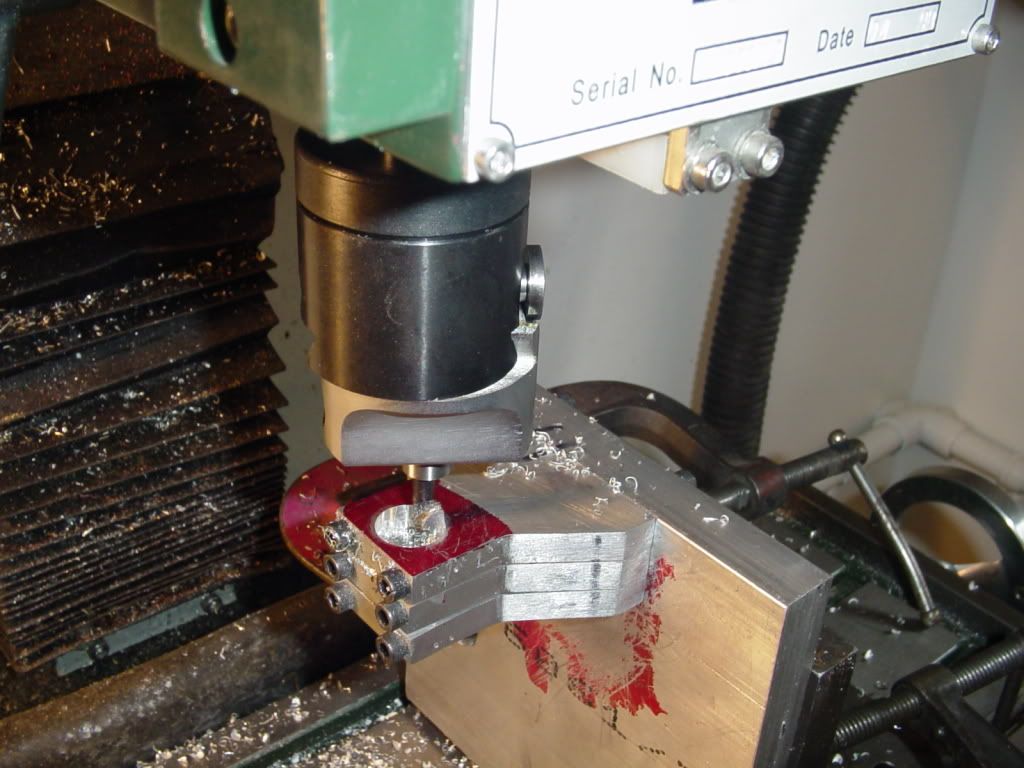
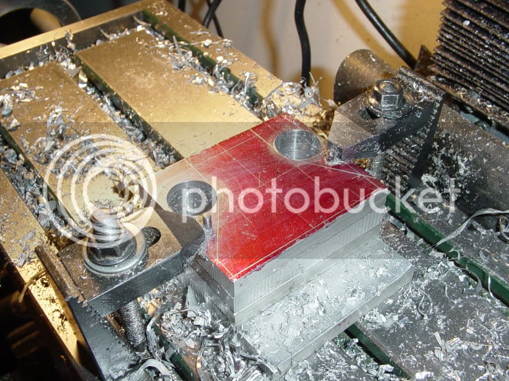
Cedge--I wasn't beating you up---Honest!!! I just never had much luck with glue. I welcome your posts and comments any time, please stick around and comment. I enjoy hearing all ideas. If some of them don't work for me, thats okay, I know some people have great sucess with them. Kludge--I used the old tried and true "magic eyeball" method of determining 90 degrees---that and a small layout square. I didn't solder them both at the same time. I soldered one, let it cool, then lined the other one up and soldered it..Compound Driver---Clamps were not an option, because I had to profile all sides of the blocks, and a clamp would have been in my way---also, with a clamp on them (I',m thinking C-clamp), there is no way they would have layed flat against the mill bed.
 
This morning I finished the bearing caps. I tapped the bearing stands, and wouldn't you know it, on the vey last bottom hole, I broke the #10-24 off right flush with the surface!!! There was no way that sucker was coming out, so I just drilled a new hole 1/4" inboard of the hole with the broken tap in it and tapped it instead. (I don't know how I got lucky enough to have an extra 10-24 tap, but I did.) I also went downtown to my metal supplier and got a couple of choice "offcuts" for $20 to make th base and the spacer block under the cylinders with. I guess my next step will be to bore the bearing stands for the ball bearings.
BRGSTANDSWITHCAPS001.jpg

BRGSTANDSWITHCAPS002.jpg
 
In a world of Wacky Setups----This is how I will keep the distance from the engine base up to the centerline of the crankshaft bore the same on all 3 bearing stands. Bearing stands bolted to flatbar, flatbar setting on parallels and clamped to angle, angle bolted to mill table. So far----So good----
WackySetup003.jpg

WackySetup002.jpg
 
This is more fun than a bag of rattlesnakes----Well, not really. This is my brand new boring head boring its very first hole. Works good, but its so out of balance that the mill wants to levitate if I run it at more than 675 RPM .
boringbeearingstands001.jpg

 
Brian .......... this is a comment not a criticism, cos' I may well be wrong ........... but .......... I couldn't have brought mi'self to drill the stands without a support under either the drill centreline or the opposite end to the clamps ............ I know it's a soft metal but deflection etc, ............. just my take mate ......... and only put it forward to spark discussion so we can all learn really.

hope it worked for you though ;)

atb

CC
 
Brian Rupnow said:
the mill wants to levitate if I run it at more than 675 RPM .


I'm not surprised really, Brian, please do me a favour and get the work clamped securely to the mill table before proceeding any further ................... call me a "worry wart" if you want but that set up frightens me ................. a lot ???

CC
 
Back
Top