Vertical 4 cycle engine from recycled parts

Home Model Engine Machinist Forum

Help Support Home Model Engine Machinist Forum:

This site may earn a commission from merchant affiliate links, including eBay, Amazon, and others.
So why did you give up on the other design? Part of this hobby is overcoming problems to accomplish a goal.
 
Just watch that your compression ratio does not drop too low. That Tee head is a lot wider than your previous one due to the outboard push rods so your passages from valve to cylinder are a lot longer and therefore have a greater volume. If you are alrady having problems getting good compression then lowering the ratio won't do anything to help.
 
I haven't run off---I've been working, working--working. The new Tee head conversion is going fine, and today I hope to tackle the valve cages and valves. I am getting a bit tired of working on the same engine, but sometimes that goes with the territory.
6K5zgo.jpg
 
Well, that's my work for today!! Two valve cages and two valves. The shanks on the valves aren't cut off yet, because that's what I hold onto when I'm lapping the valves into the guides with 600 grit aluminum oxide compound. Once I have what I assess as an "airtight seal" the shanks will be cut off the valve stems.
4x3O67.jpg
 
Good stuff as always Brian. I know you have done your Tee-head before so it works. But I am amazed at the combustion chamber from Valve to cylinder - being a long narrow passage - as that should cool the flame almost to death in that zone? I wonder what the exhaust will smell like? - Sweet with fuel?
But you like to do the extraordinary, which is why we are so fascinated (and impressed) by your builds.
K2
 
And at the going down of the sun----The engine is now configured as a tee head style. Many changes were made to the head and valves and valve lifting mechanisms, but thankfully the rest of the engine didn't change. Tomorrow I will time the ignition and the valves, say a little prayer, and try this engine again.
9QQZ1l.jpg
 
Good stuff as always Brian. I know you have done your Tee-head before so it works. But I am amazed at the combustion chamber from Valve to cylinder - being a long narrow passage - as that should cool the flame almost to death in that zone? I wonder what the exhaust will smell like? - Sweet with fuel?
But you like to do the extraordinary, which is why we are so fascinated (and impressed) by your builds.
K2
I've always thought that T-heads managed to incorporate the worst of both sidevalve and DOHC into one design.

Doubtless the engine will low powered, inefficient, and have dirty exhaust by the standards of a more modern design style. But that doesn't matter much for a model that just idles a few minutes once in a blue moon.
 
I don't really know that much about Tee head engines. It was just something different to build. I've never actually seen a real one. All I know is that at some point in the past they were installed on Gravelly garden tractors.---Brian
 
I would severely limit the cooling fins in the zone towards the inlet valve, and to a lesser degree towards the exhaust valve, to try and keep the combustion chamber temperature high for combustion to progress as far as the valves... But as a model it should work as well as on garden tractors.
1702109177664.png

1702109331273.png


1702109440466.png


Enjoy!
 
I for one was tickled to see Gravelys discussed. I've rebuilt 6 or seven and have a collection of 7 or 8. The old T head models have a full pressure oil system that supplies the engine and the trans axle. I consider them the Rolls Royce of american walk behind tractors. The only belt is a fan belt. There are a plethora of attachments out there. They can be found pretty cheap now and are pretty cool.

The Italians make some really interesting walk behind models as do the orientals, seldom seen here in the US.
 
just observing... in the picture I attached of the Gravely engine - taken from a video - the spark-plug looks to be at a 45degree angle pointing towards the inlet valve? Is this correct Vietti? Maybe you can comment of the design for those of us who have never met these engines?
Ta,
K2
 
Looked at my easily accessible version and the plug is vertical, I'm no expert on Gravelys and since spending my time on models I don't remember much. They were rated at 7.6 hp and had a long stroke and good torque, relatively at low rpm. Another advantage of the T head was a cross flow configuration so the carb was on the opposite side of the exhaust so the carb stayed cooler and some overlap was possible. At some point they abandoned their own engine and started using Wisconsin Kohler and maybe Briggs engines. I think their molds burned up and it was easier to out source the engines.
 
This weekend I didn't do very much.--Even I get tired of working on model engines once in a while. I did move a mounting hole in the gas tank because it set crooked. I spent the major portion of this weekend rereading a book by Wilbur Smith. He wrote such absolutely marvelous books, and now nobody writes such thrilling "mans adventure" stories. I miss Wilbur, same as I miss Bradbury and Heinlein and Asimov.
 
Today I am testing my Tee head cylinder, cylinder head, and valves for air leaks under pressure. I made up a cast iron fixture to seal the bottom of the cylinder and screwed my new compression tester into that. At the other end, I took out the sparkplug and screwed in a fitting which allows my regulator to screw into that end. In a perfect world, as I increased pressure on the regulator, the gauge would record the highest pressure I could exert inside the cylinder, and would show up any leaking valves. However, in my world, the fittings on the ends of the compression tester which are sealed with rubber o-rings leak like Hell. So---Now the rubber o-rings have been taken out and 638 Loctite applied to all the mating threads. I will leave it like that for a few hours and then try this exercise over again.---Brian
qUqQln.jpg
 
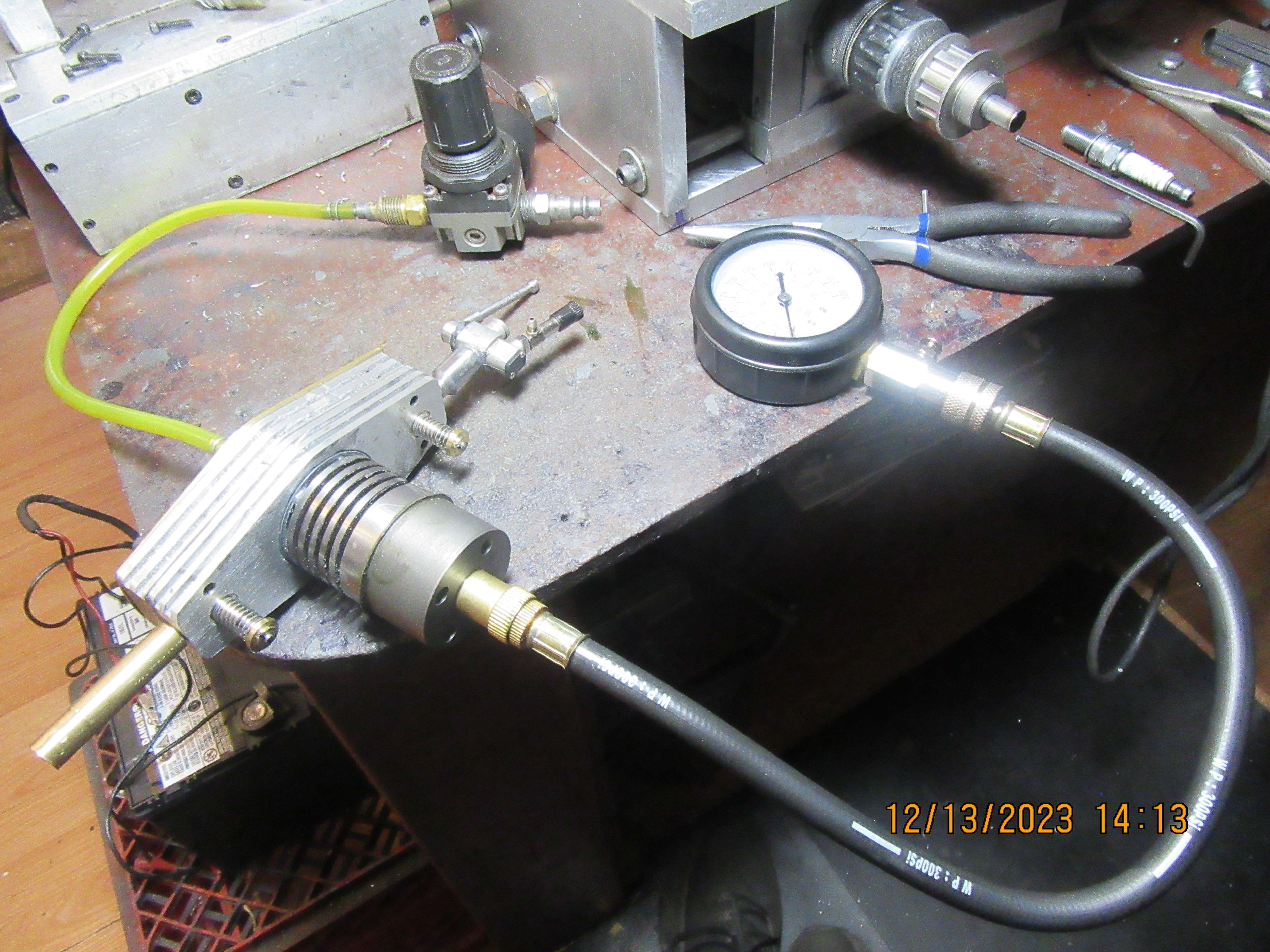
Initial air testing to find the leaks is great fun! (Not). I use a low displacement compressor, tyre inflator, etc. That only pumps enough air to put a few psi in the chamber/ system I am testing. Then, as it is a continuous supply, I put the job in a bucket of water and watch where the streams of air bubbles are developing. Use PTFE plumbers tape on screwed pipe joints.
When the job will hold 40 psi (limit of my worn fridge compressor) and I can't find any more bubbles, I consider it good enough for an hydraulic test and then pressure relief valve test. (I am usually testing boilers).
K2
 
I don't see the point in using the compression tester as you show it there. All it will show is the same that your compressor shows. Would get the same result with the plug left in and compressor to the CI fixture. In Fact a better test as it would show if there was any leak from the plug as well as the head gasket and valves
 

Latest posts

Back
Top