Topsy Turvy Hit & Miss Engine Build

Home Model Engine Machinist Forum

Help Support Home Model Engine Machinist Forum:

This site may earn a commission from merchant affiliate links, including eBay, Amazon, and others.
Harold,
A good logical thought, And for sure that was the way to go. Probably You've already thought of it, But I've cut a few items like your cam on a R/T. I'd really recommend cutting a test sample first to get your R/T settings perfect. It would be really handy if these R/Ts came from the factory's with adjustable table stops for doing work like this. I can mostly laugh about it now, But my last fiasco with a R/T I went about 1 degree too far. If the design was supposed to have that built in divot the part would have been perfect.

Pete
 
Before I move on to cutting the cam on my gear I decided to make a few no-brainer parts to boost my confidence.... I decided to work on the left side of the engine and make the camshaft and the pushrod guide. The camshaft was a two setup operation. First I turned the shaft and drilled and tapped the 6-32 screw for holding the cam.

TopsyTurvyOct27-01.jpg


Next I turned the part around and chucked it in a collet and turned and threaded the back side that screws into the engine base.

TopsyTurvyOct27-05.jpg


The next part was the push rod guide... It was very straight forward and just a matter of marking, milling, and drilling holes as well a little file work to break the edges...

TopsyTurvyOct27-08.jpg


Here are the two parts mounted on the engine...

TopsyTurvyOct27-09.jpg


Ok... That boosted my ego a bit... Next I'll tackle the cam. More to follow...


The assembly is shaping up as an impressive ego boost Harold. Very nice

Steve
 
Thanks Steve.... This project was a bit intimidating since there were operations that I had not done before. Like the crankshaft, the engine body. But with the other parts taken one at a time they tick off and soon there will not be any more to make... I find the easy ones help to smooth out the difficult ones...

Harold
 
After the small "ego boosting" projects, it was time to cut the cam. The first step was to set up the rotary table on the mill and using a coaxial indicator to get the spindle centered over the RT.

TopsyTurvyOct27-11.jpg


My procedure was to mill the two endpoints and then mill the rest of the cam. The OD of the cam was 1.00 and the body diameter was .687. I indicated the mill and then moved toward the center .156 or half the diameter difference. The endpoints were at 0 degrees and 218 degrees using a 3/8 endmill. I wanted a .004 lip on the cam so I milled to a depth of .246

TopsyTurvyOct27-12.jpg


On my RT I used three clamps and moved one at a time to provide clearance for the mill.

TopsyTurvyOct27-14.jpg


After cutting the body down I then set the RT to the two endpoints and milled straight out to provide the lobe.

TopsyTurvyOct27-18.jpg


TopsyTurvyOct27-19.jpg


After this it was a little file work to break the edges on the lobe and that part was done... WHEW!!!

TopsyTurvyOct27-20.jpg


TopsyTurvyOct27-24.jpg


Although I am very pleased with the results, If I did it again I would do things a little differently. When I milled the two endpoints there was a few thousandths of movement when I milled them due to the rigidity of my small mill. This caused two dimples at the endpoints. The next time I do this I will not index to the finished dimensions; rather I will leave about .005 and then take a finish pass. Although it would not improve the functionality, it would make a more cosmetically pleasing finish.

Next step is to locate and drill and counterbore the two screws for holding the ignition lobe.

 
I realized that I do not have the bronze material to make the ignition lobe so I decided to go ahead and make the countershaft bracket. After milling the material to size, I slathered it with dykem and did a layout of the part...

file.jpg


The first step was to locate then drill and ream the shaft holes. This was done before the part was machined to provide rigidity. I drilled and reamed a hole at each end about 3/8 deep.

file-1.jpg


file-2.jpg


The part was then placed in the mill and the center material was removed to finished dimensions.

file-3.jpg


The part was flipped upside down and the two holes were located and drilled. The extra thickness of the back was removed down to the 3/32 thickness.

file-4.jpg


file-5.jpg


All in all I was very satisfied with the results.

file-6.jpg


file-7.jpg


file-8.jpg


Hmmm... Must be five o'clock somewhere...
 
One of my High School students made a Duclos Topsy Turvy. He didn't quite get it to the running stage but it was far enough along to win the Grand Award 5 or 6 years ago at the Michigan Industrial Education Awards Fair. This awards fair, after regional elimination, involves maybe 500 metal shop projects.
 
jpeter - I would have to say that was quite an accomplishment for a high school student. I was not a machinist in my profession but at 65 years old, this is taxing my abilities and patience...

That being said, I really love Philip Duclos' designs and think most of them are very aesthetically pleasing as well as running very well.
 
Looking good Harold. Starting to really look like an engine :bow:
Brock
 
Brock & Brian - Thanks for keeping up. Right now I am working on a short project which it taking up all on my machine shop time. I hope to be back on this about the middle of next week.

Brian - I have read your Ice House Cat story to every one that will listen (my family). We have had many belly laughs from it and you have brightened many days with your story. Thanks for sharing it.

Harold
 
After a few week hiatus to do a "quick G job" for a friend, (note to self... there are no quick G jobs!!!) I was able to get back on the engine build. I actually built three parts. The first on was the governor trip arm. I did not think a series of photos was warranted since it consisted of milling the part to size, drilling and reaming the shaft hole and drilling and tapping for the setscrew.

file-18.jpg


file-17.jpg


The next part was the governor weight. It was a turning, milling, and drilling operation.

file-11.jpg


file-12.jpg


file-13.jpg


file-14.jpg


The next big part is the flywheel. I turned it out of a 5 1/2 inch chunk of 12L14 CRS. I faced one side and using that for a reference I turned it around, chucked it in the four jaw, indicated it in, and completed one side.

file-19.jpg


To make sure the shaft hole is true, after center drilling it, I drilled it with a 27/64 drill, then I bored it to .010 under, and finally reamed it with a .375 reamer.

file-19.jpg


file-20.jpg


file-21.jpg


After this step I machined the first side to dimensions...

file-23.jpg


I then flipped it over and indicated the second side in and machined it to final dimensions.

file-25.jpg


file-27.jpg


file-28.jpg


The next operation will be to cut the spokes for the flywheel. I am a little intimidated by this step. On all of the previous bar stock flywheels I have made there were holes instead of spokes. On this one I actually have to cut the spokes and while it is fairly straight forward. I only have a four inch rotary table and the flywheel is 5 3/8 in diameter.

file-30.jpg


That will be the next operation on the list...

file-29.jpg


Harold,
Very nice work as per usual. Your going to need a subplate bolted to your Rotary Table. The last time I did that on my 6", I just used some 1" thick aluminum plate with counter sunk allen head bolts into tee nuts in the table slots. Once it was bolted down I just flycut the plate by moving over on the X axis and then rotated the table around till the plate cleaned up. You could then drill and tap to hold the outer perimiter of your flywheel using the mills normal hold down set. It takes a bit of patience till you get the flywheel concentric with the table rotation though.

Pete
 
pete said:
...SNIP...
Your going to need a subplate bolted to your Rotary Table. The last time I did that on my 6", I just used some 1" thick aluminum plate with counter sunk allen head bolts into tee nuts in the table slots. Once it was bolted down I just flycut the plate by moving over on the X axis and then rotated the table around till the plate cleaned up. You could then drill and tap to hold the outer perimiter of your flywheel using the mills normal hold down set.
...SNIP...
Pete - Thanks for the suggestion. I was thinking along those lines but had not firmed it up. I have some 1/2 inch aluminum tooling plate and I will look at it for making the subplate. The one concern I have on the size of the RT is I need to rotate it while milling the outer edges of the spokes. I wonder if I will have enough oomph and rigidity. Any thoughts?

Harold
 
Looking good Harold

Another possibility would be to mount your 4 jaw onto your rotary table. If you can manage a suitable adapter plate without too much trouble you're set. I'm not sure how your chuck mounting works though, so may be too difficult.

patience, light cuts and a tiny bit of good fortune should make up for what's missing in oomph and rigidity. You only need to use a 1/4" cutter, you should be right.

Cheers
Steve
 
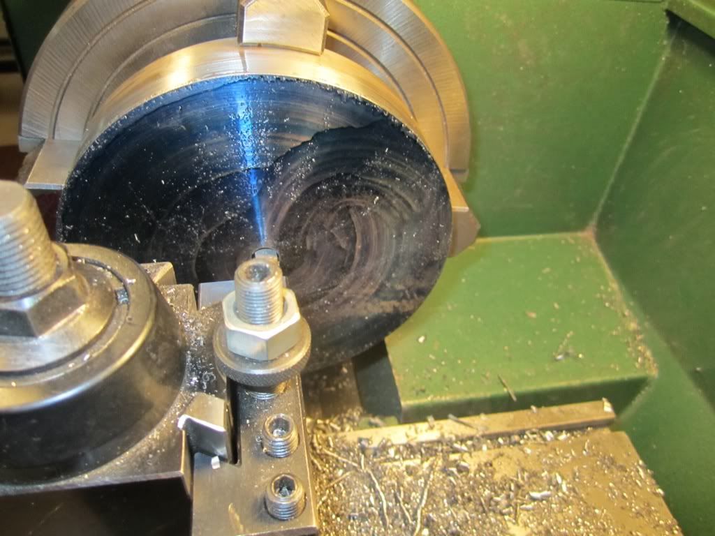
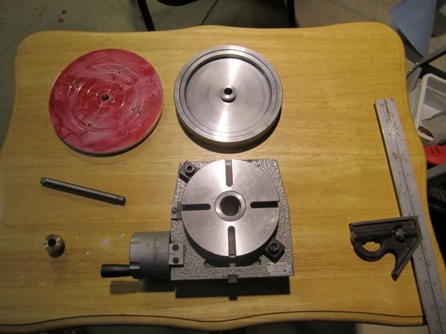
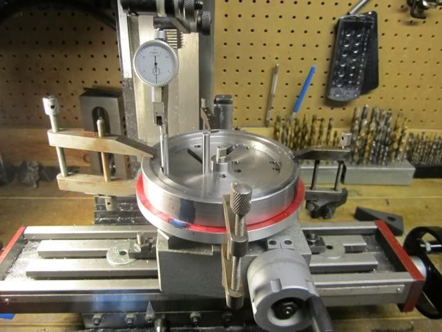
Steve - Thanks for that suggestion but my 4 jaw is way too big and too heavy to mount on the rotary table. I do have a four inch 4 jaw that fits it but it will not hold the flywheel. My lathe 4 jaw has the spindle threads as part of the casting so it would take some finagling to get it secured. I took Pete's suggestion and made a larger plate. In the past I have wished I had "just another inch" on my rotary table and this will give it to me.

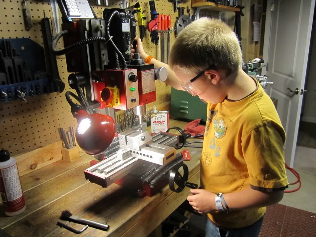
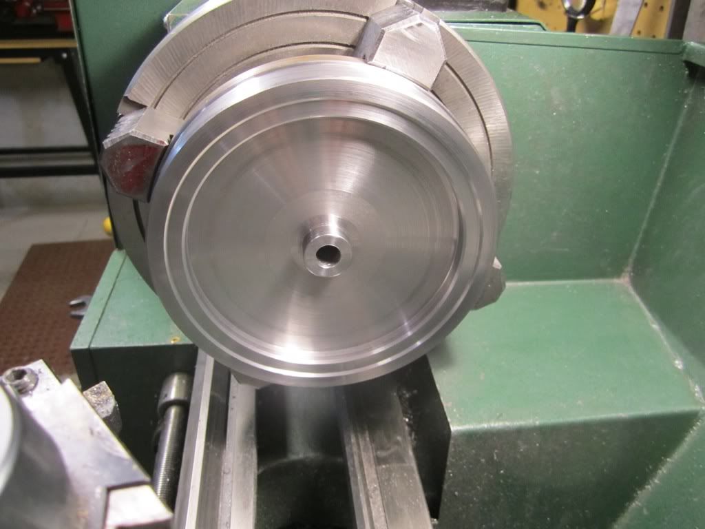
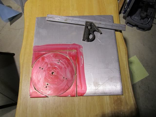
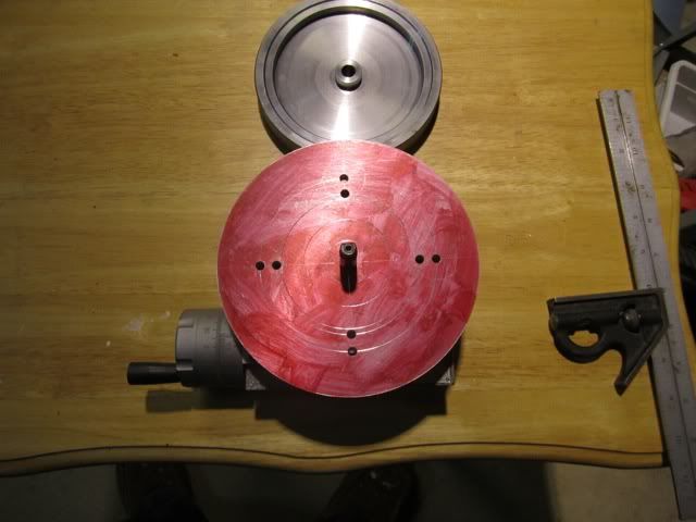
I didn't show a step by step of the plate construction but I sawed it out of a piece of aluminum tooling plate, and finished it on the lathe.

file-33.jpg


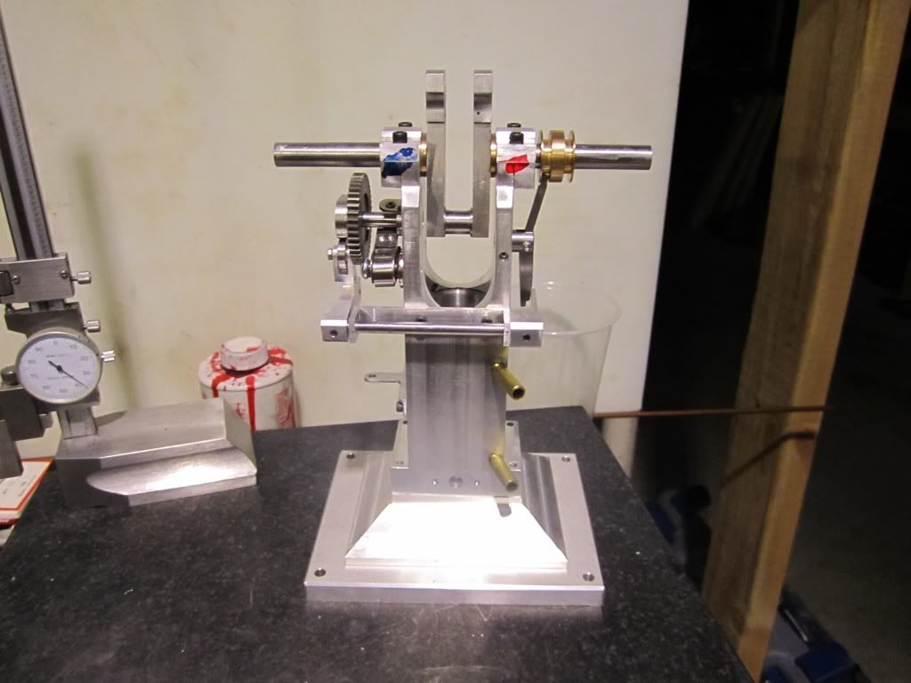
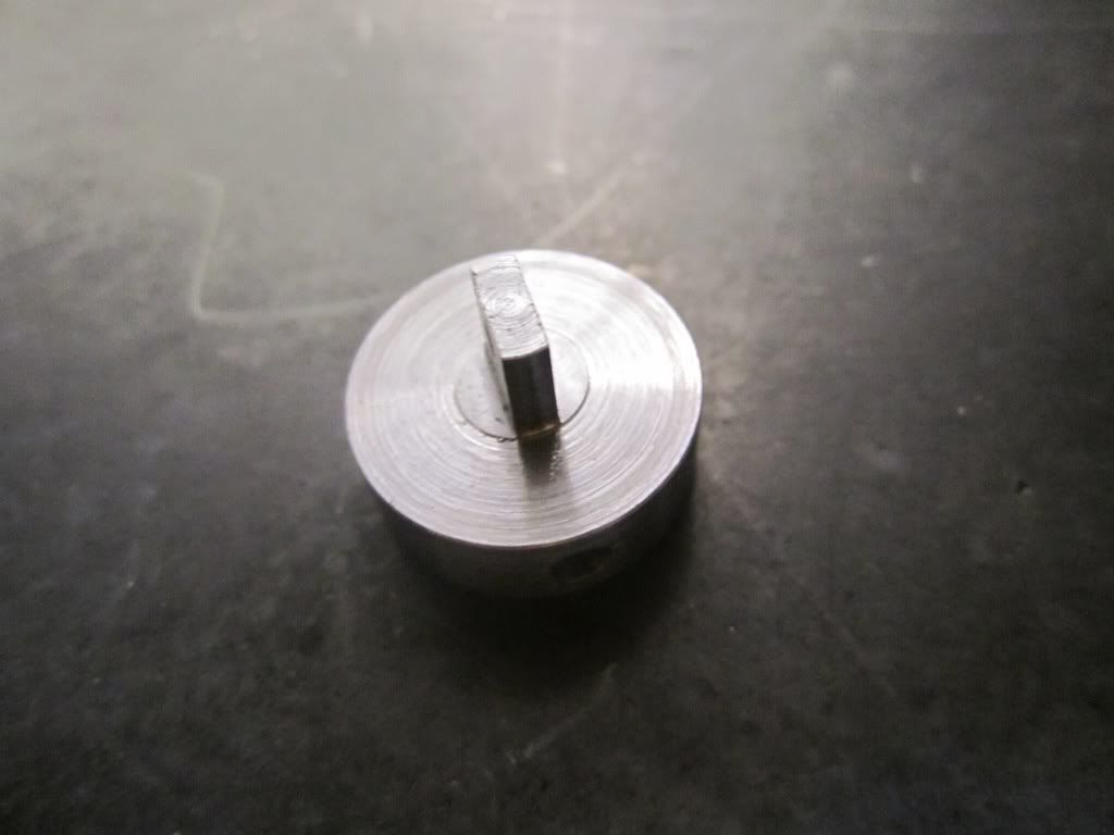
The two sets of holes are for mounting it on the lathe to turn the edges (outside holes) and the other holes are for mounting it on the rotary table.

file-34.jpg


file-35.jpg


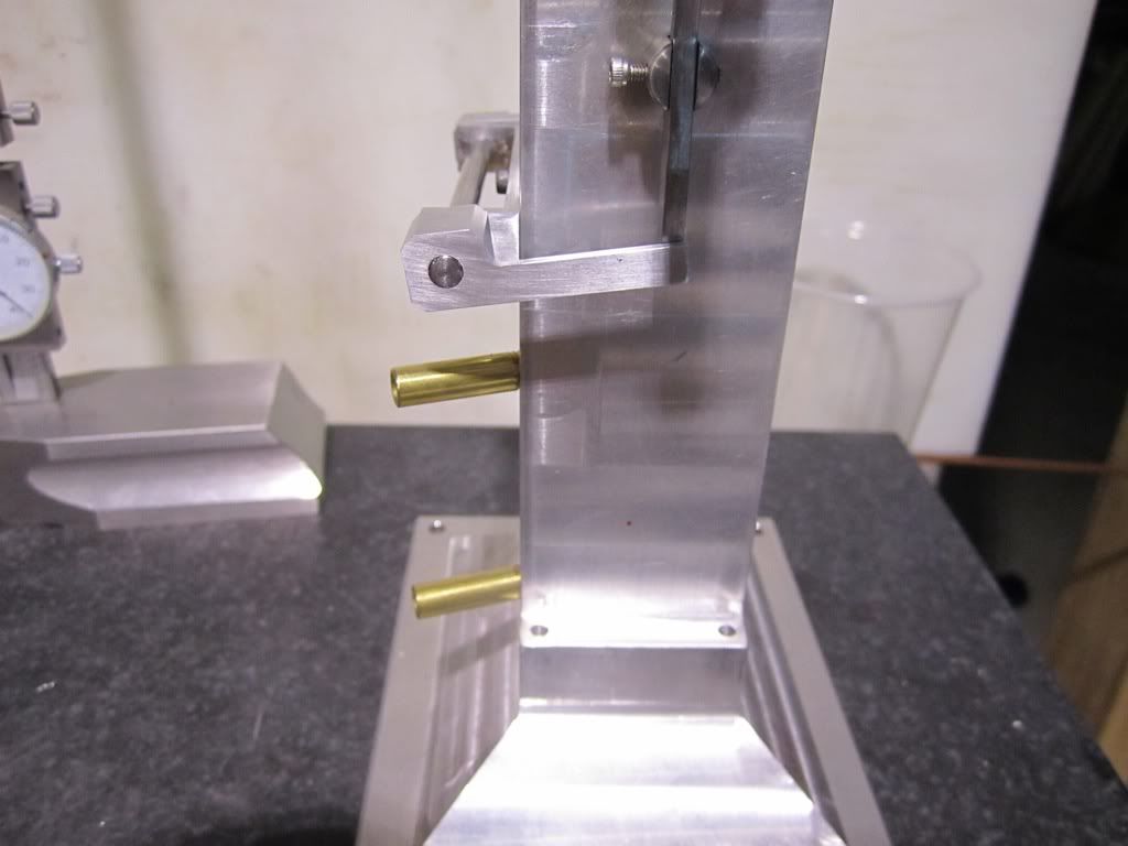
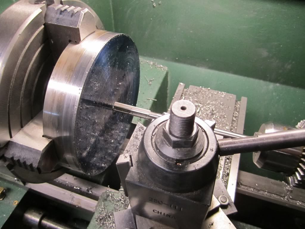
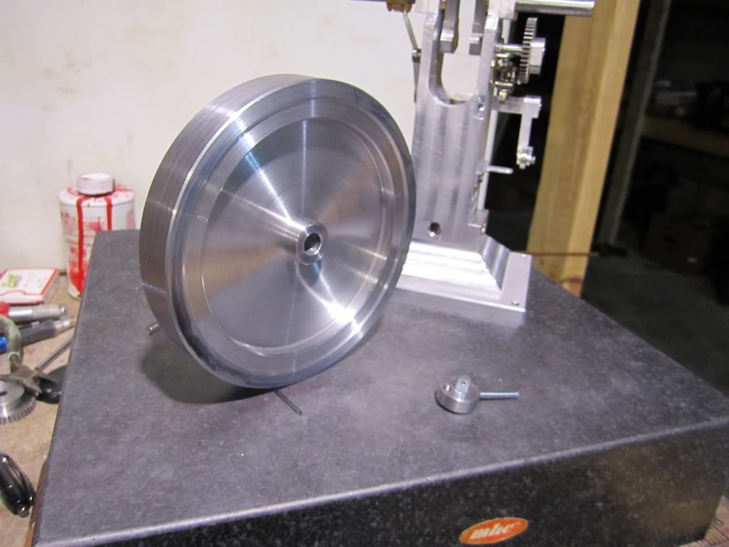
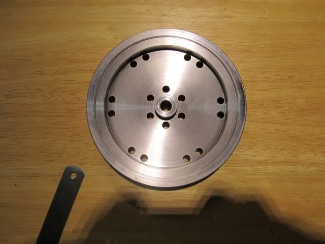
Since the flywheel is cut away on the diameter of the mounting holes I did not need to countersink the mounting bolts.

file-36.jpg


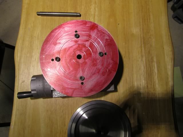
In retrospect I wish I had made it about a half inch larger and I could have drilled and tapped so clamp holes on the periphery but I was also concerned about making it too large and not being able to read the vernier dial on the crank.

file-37.jpg


file-38.jpg


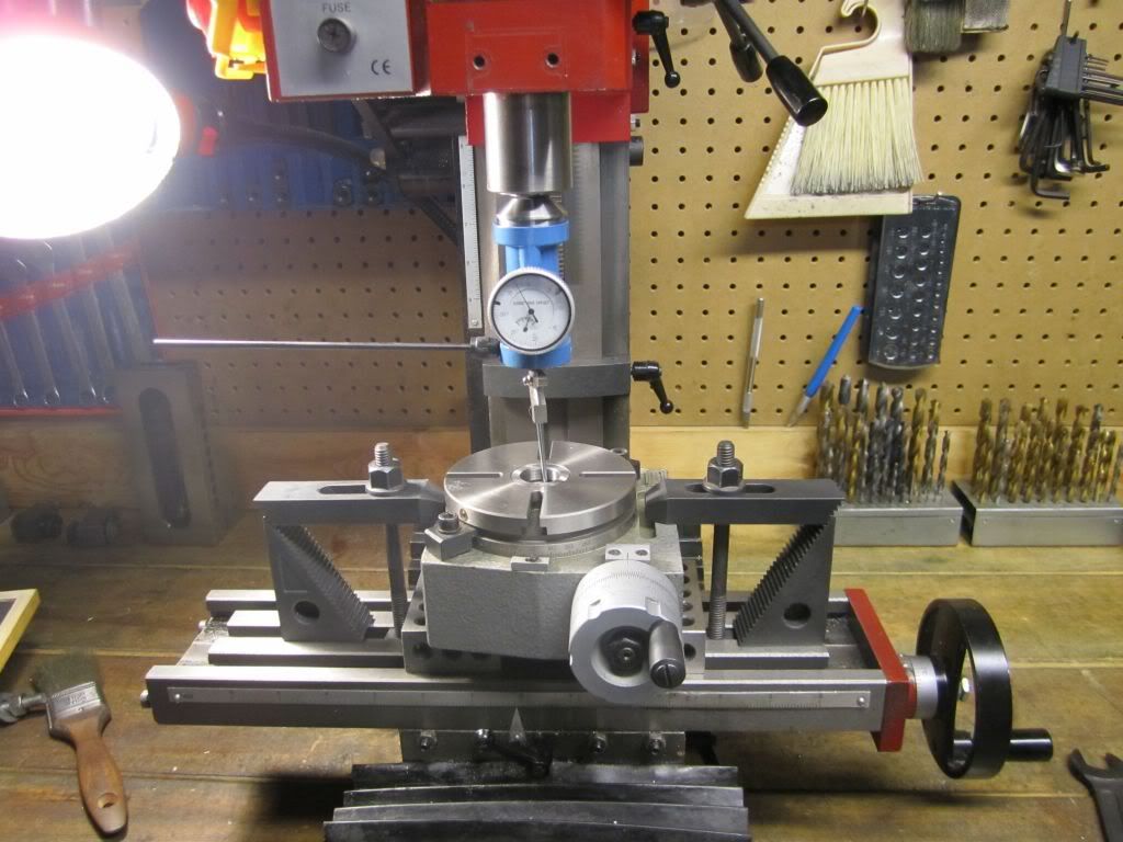
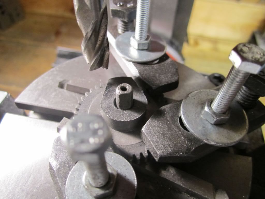
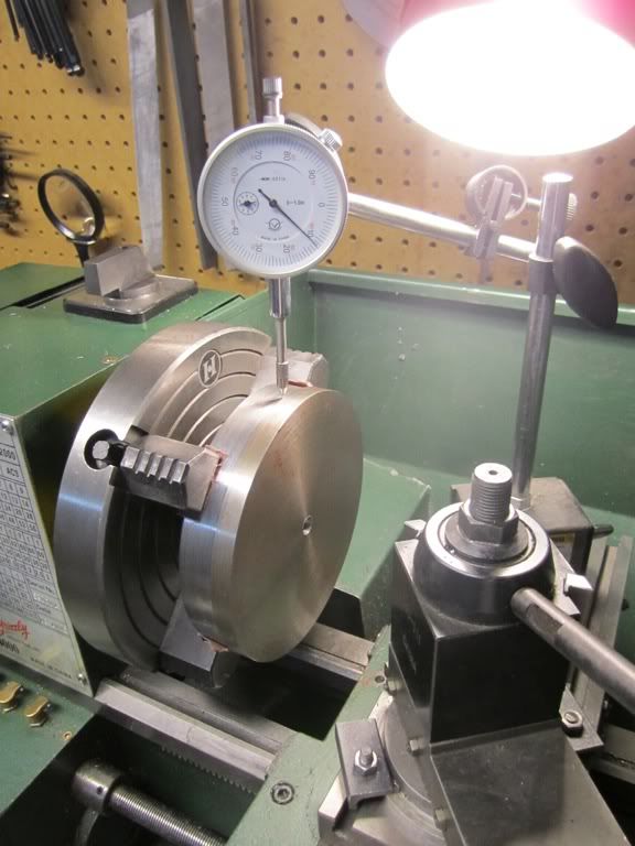
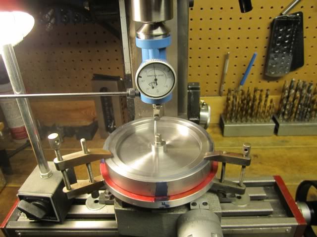
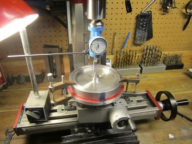
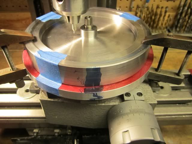
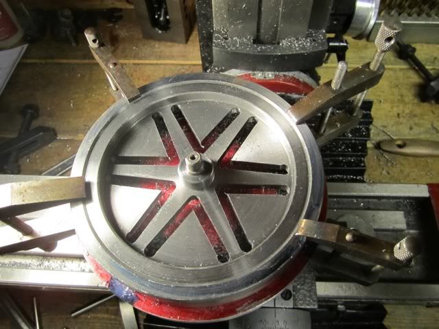
I made three "witness" marks around the edge and used machinists clamps to hold the flywheel to the table. This was a pain because I had to move them one at a time as they rotated to clear the dial. After this it was a matter of locating the spindle and starting to make holes. I also put some tape in three places to serve as additional witness marks since it would show if the flywheel moved. I was not too concerned since there was no rotational force on anything at this point.

file-39.jpg


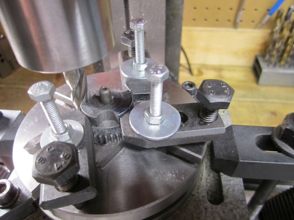
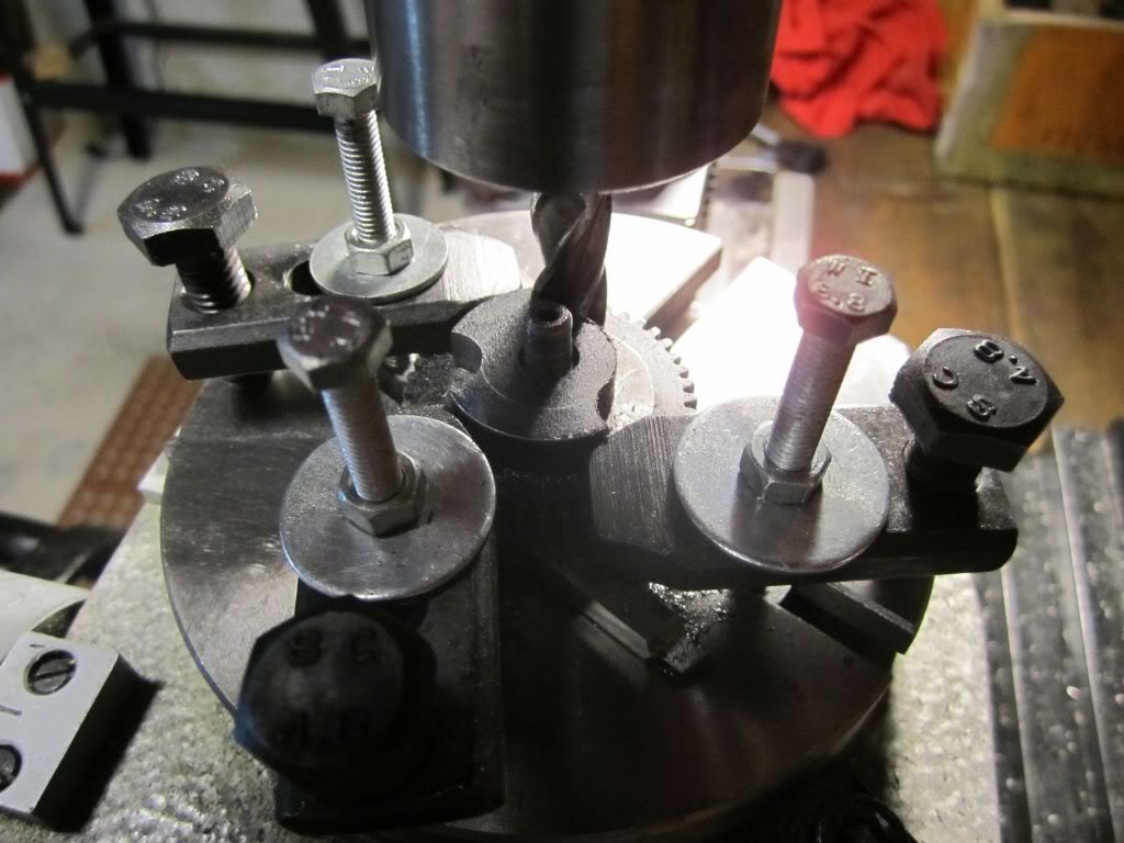
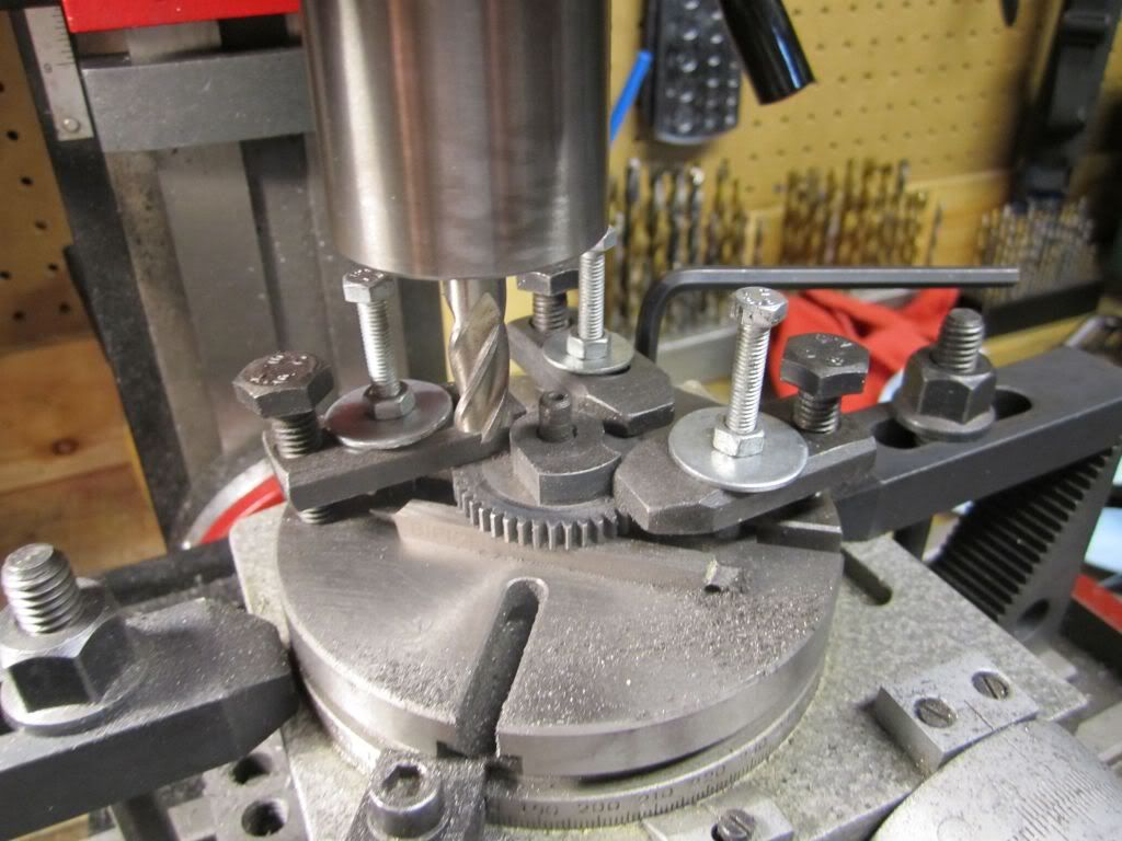
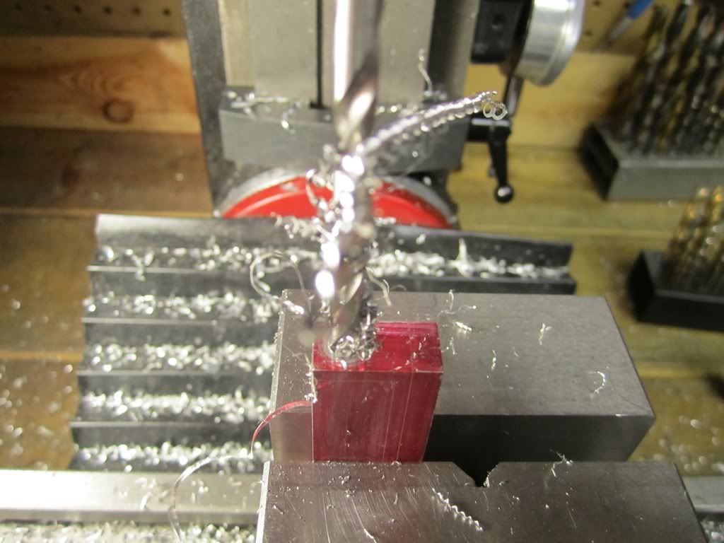
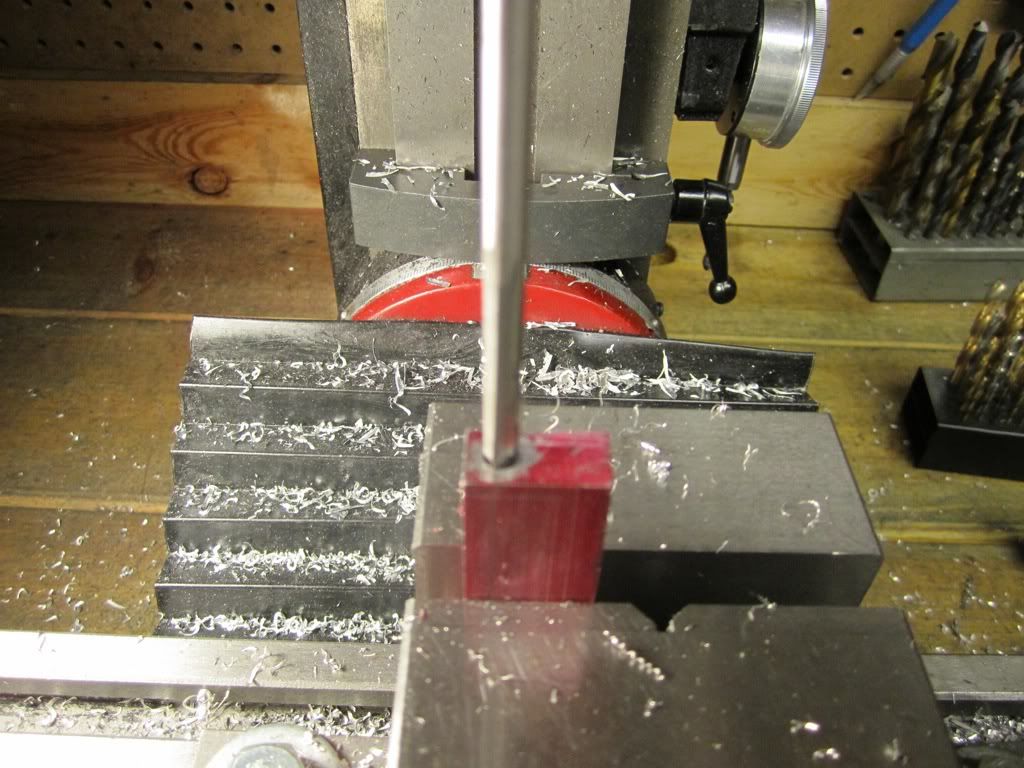
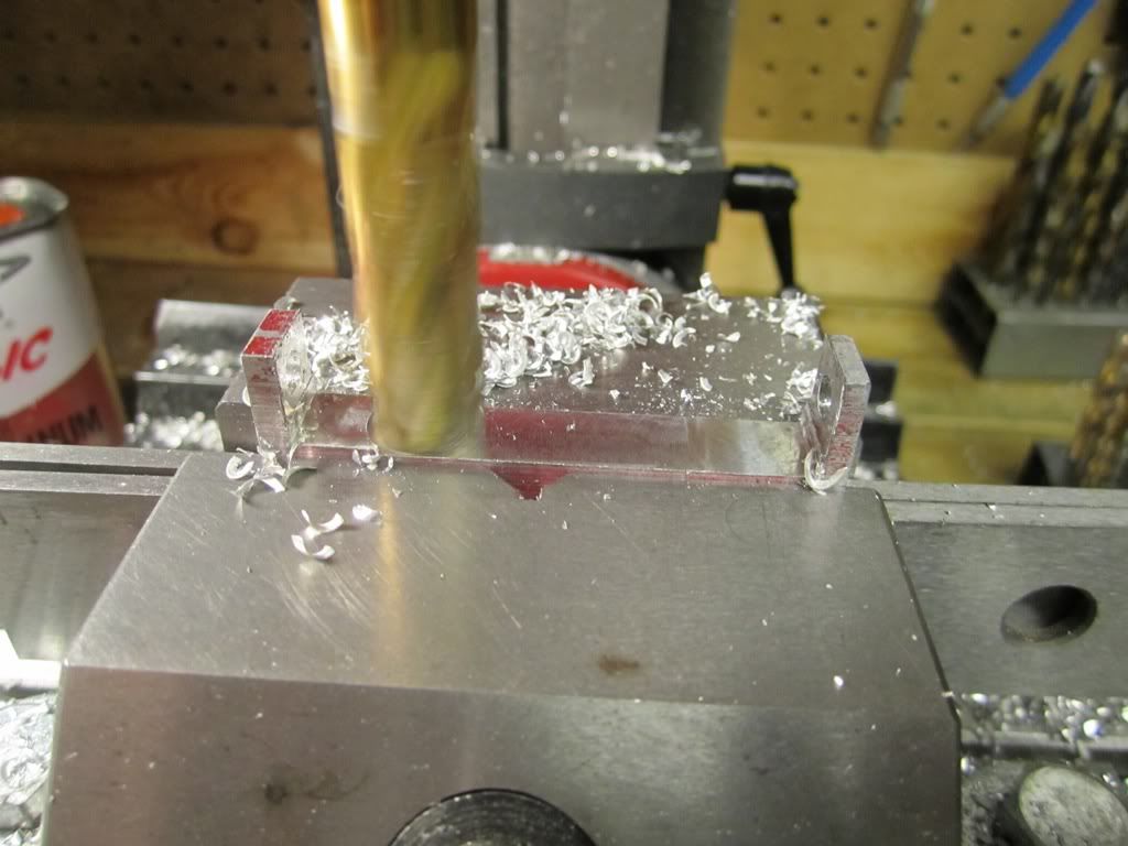
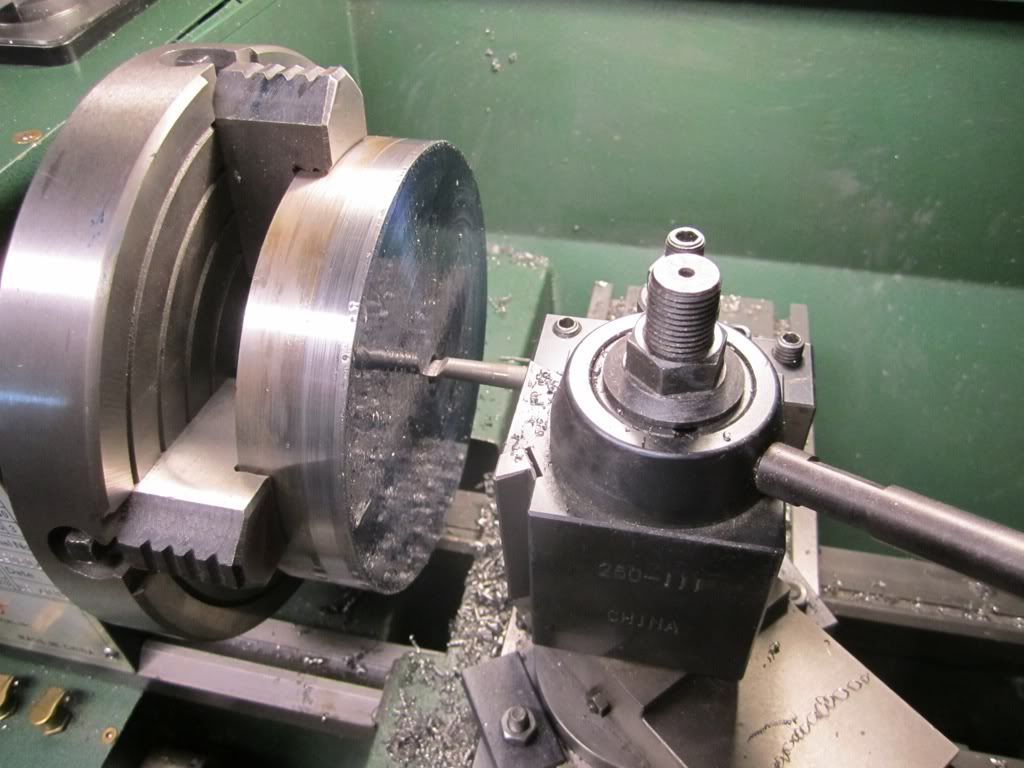
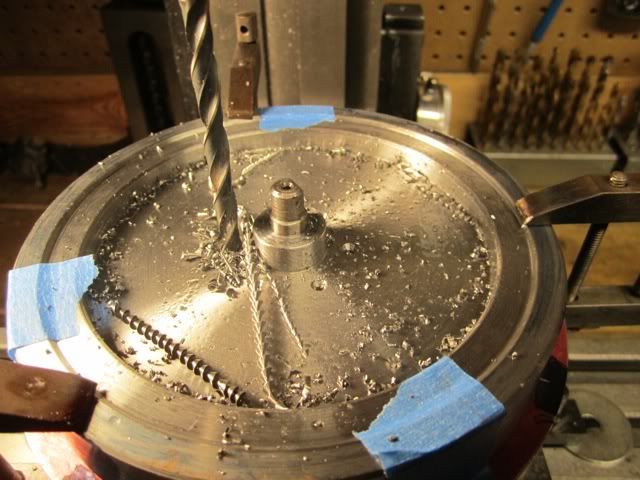
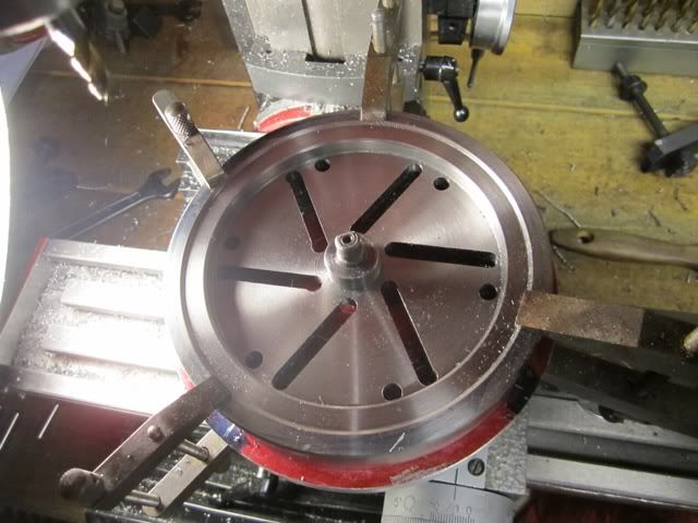
For each hole I indexed 60 degrees, center drilled and repeated. I then put a 15/64 drill in and indexed and drilled and finally a .250 reamer and indexed and reamed each hole.

file-41.jpg


file-42.jpg


file-43.jpg


This ended up being a a pain with having to move the clamps around and on the outer holes I would index, center drill, then drill, then ream. It made for a lot of changing drill but it only required moving the clamps around a minimal amount.

file-46.jpg


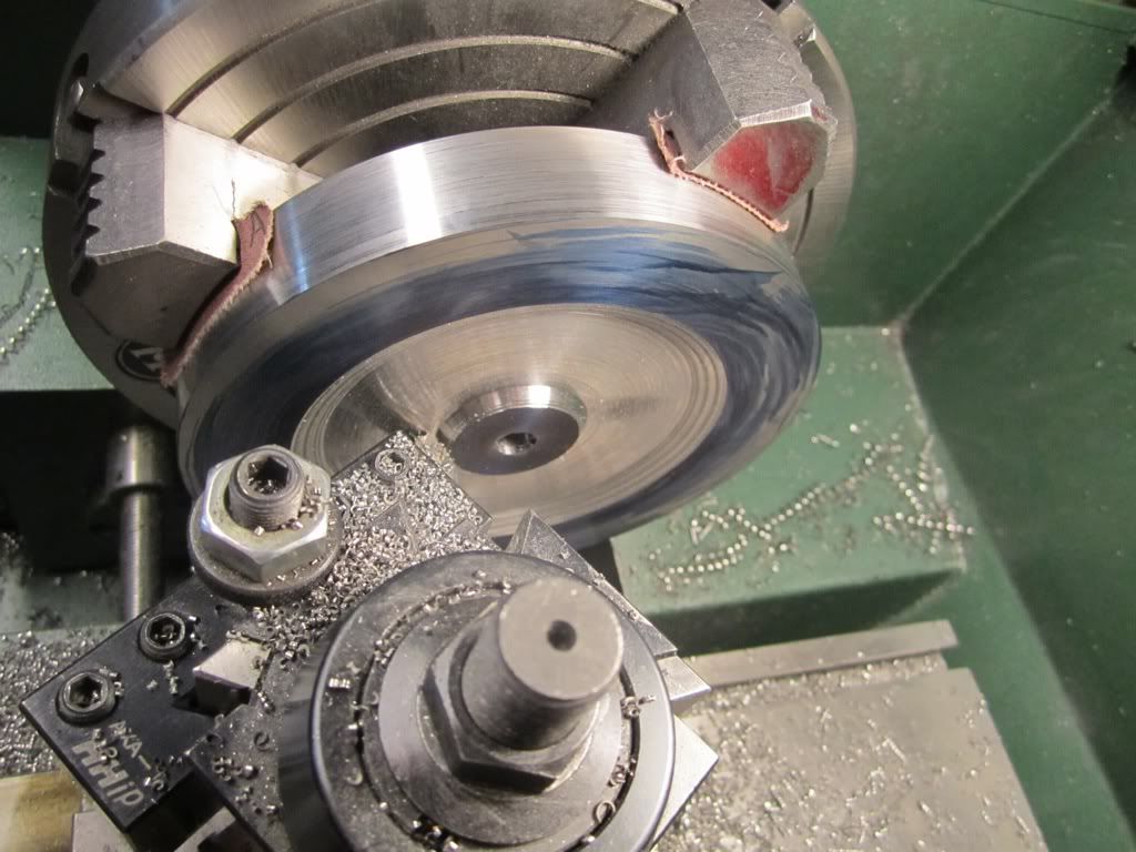
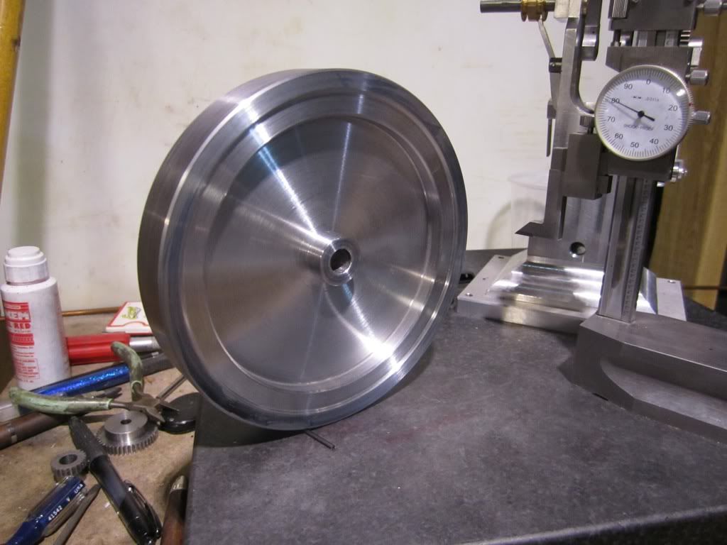
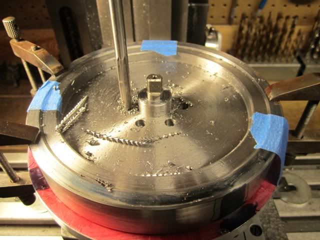
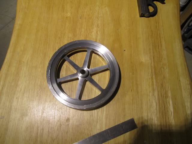
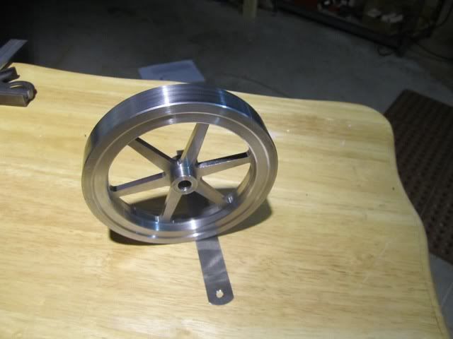
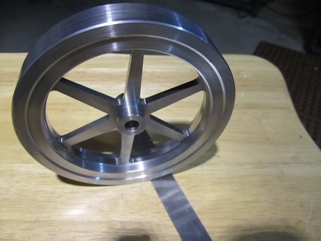
I was quite happy with the results...

file-47.jpg


file-48.jpg


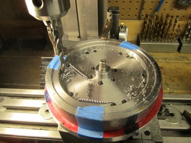
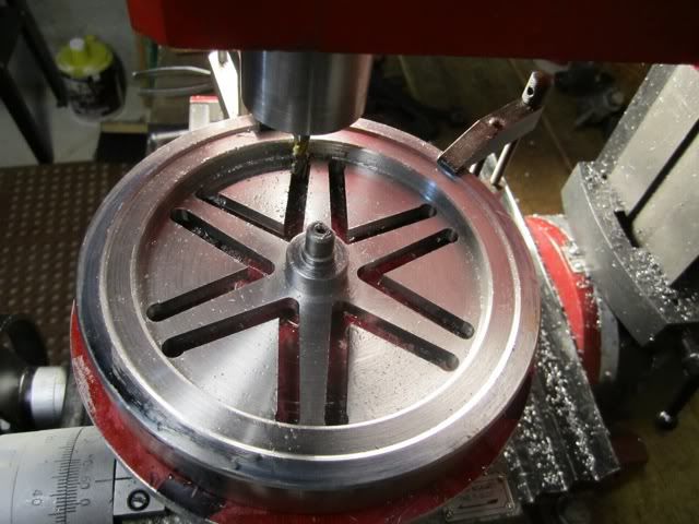
A valid question would be "why the need to drill and ream the holes since they will be milled away?" The reason is, I wanted to use two dowel pins to align the flywheel on the mill table and wanted to have a close tolerance hole for the pins. Maybe a little overkill but at this point I do not want to mess it up.

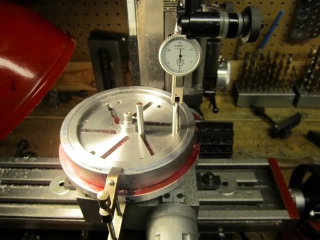
The next step is to mill out the webs....


Harold,
I think that was a very smart move reaming all the holes. It should be real easy to check against both hole locations on each end of the spokes till there both lined up dead on for your table travel. Your method should be an easy way to ensure that there's no mistakes. That alone makes all those tool changes worth it in my opinion.

Pete
 
The next step of the flywheel build was to put the flywheel on the rotary table and cut out the webs. Since I was using a four inch table, I only cut .020 at a time and made multiple passes. The first step was to get the spoke edge true with the mill table travel. Using pins and an indicator I was able to get it within .002 which was probably overkill but at this stage of the machining I didn't want to take a chance of messing it up. After getting the first one indicated and true, I was able to get the subsequent slot alignment within .005 by just rotating the table 60 degrees and then with the indicator get it closer. The one issue I ran into is my larger table plate extended beyond the locking screws but I was able to use a pair of pliers to lock it down for the cuts.

file-49.jpg


in order to minimize a chance for mistakes, I cut all of the edges on one side first and then cut the second at the same time.

file-50.jpg


The end mill I used for milling out the slots was a 7/32 end mill. This gave me .032 clearance on the end holes which allowed a finish cut along the edges after milling. In addition it also allowed the .250 pins to have a close fit at the hub even after cutting the first slot.

file-51.jpg


At this point it was just step and repeat... Notice by looking at the slots that the mill was smaller than the holes.

file-52.jpg


At this point it I centered the flywheel using the co axial indicator and then cut the outside edge.

file-53.jpg


I was very pleased with the results.

file-55.jpg


file-54.jpg


file-56.jpg


I still need to chamfer the edges of the spokes, locate and drill the hole for the governor pivot. The drawing calls for two 6-32 holes 90 degrees apart and a keyway slot. On my past engines I have always had trouble with this design coming loose and I am going to machine a taper lock hub. I actually went back and retrofitted all of my previous flywheels with this and have not had a single problem since. This technique is discussed in issue 11 of the "Model Engine Builder" magazine as well as "Steam & Stirling - Book II" from Village Press.


Latest posts

Back
Top