
You are using an out of date browser. It may not display this or other websites correctly.
You should upgrade or use an alternative browser.
You should upgrade or use an alternative browser.
Topsy Turvy Hit & Miss Engine Build
- Thread starter Harold Lee
- Start date


Help Support Home Model Engine Machinist Forum:
This site may earn a commission from merchant affiliate
links, including eBay, Amazon, and others.
Harold Lee
Well-Known Member
- Joined
- Apr 23, 2008
- Messages
- 236
- Reaction score
- 2
Pete & Dan - Thank you very much for your encouragement. I am hoping that my build will inspire others since I believe "if I can do it, anyone can". If that happens perhaps I'll be able to provide some guidance since I have been down the same road. Please feel free and jump in if there are hints, tips, or constructive criticism you can provide.
Today was one of those "light" days where I had other tasks but felt I needed to make something so I feel I was moving forward. Since I have the upper end crank and bearings complete I decided to make the governor spool since it was a relatively easy task. This is one that does not require any in process photos since it is just basic turning, drilling, reaming and parting tool work. The plans called for this part to be made our of cold rolled steel but I decided to make it out of bronze for two reasons. 1. it acts as a bearing of sorts since it provides the coupling between the governor weight and the arm which are both made from steel. 2. I just wanted to make something that was shiny. My kids call it "shiny syndrome".
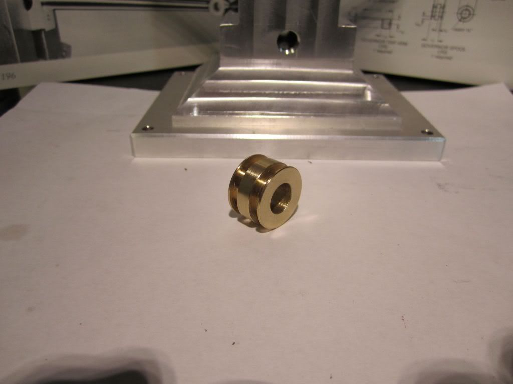
The one thing that is different when working with bronze is the tendency for the tools to dig in. A professional would have a special set of drills ground with much different geometries than the standard drills. I have found that you do not try to incrementally drill bronze since it will snatch the drill and make a mess of the part. I will center drill the part and very carefully and slowly drill the part until I am past the center drill depth. At this point it is fairly clean sailing. In this case where the final diameter was a reamed .376 (I have a .001 set of over and under reamers) I used a letter "U" drill (.368) and then reamed it to final size. If I am doing a real critical part, I will drill about .015 under, then bore the hole to true it up in the event it has wandered off a few thousandths, then ream the final few thousandths to size.
Today was one of those "light" days where I had other tasks but felt I needed to make something so I feel I was moving forward. Since I have the upper end crank and bearings complete I decided to make the governor spool since it was a relatively easy task. This is one that does not require any in process photos since it is just basic turning, drilling, reaming and parting tool work. The plans called for this part to be made our of cold rolled steel but I decided to make it out of bronze for two reasons. 1. it acts as a bearing of sorts since it provides the coupling between the governor weight and the arm which are both made from steel. 2. I just wanted to make something that was shiny. My kids call it "shiny syndrome".
The one thing that is different when working with bronze is the tendency for the tools to dig in. A professional would have a special set of drills ground with much different geometries than the standard drills. I have found that you do not try to incrementally drill bronze since it will snatch the drill and make a mess of the part. I will center drill the part and very carefully and slowly drill the part until I am past the center drill depth. At this point it is fairly clean sailing. In this case where the final diameter was a reamed .376 (I have a .001 set of over and under reamers) I used a letter "U" drill (.368) and then reamed it to final size. If I am doing a real critical part, I will drill about .015 under, then bore the hole to true it up in the event it has wandered off a few thousandths, then ream the final few thousandths to size.
You asked for any tips?
When it's possible due to hole size or length I always try to single point bore the hole slightly undersize using a boreing head after drilling and before reaming. A lot of people think a drilled hole has to be round and straight just because the drill bit is round and straight. That depends on the defination of round and straight. But to be honest, Drill bits do not drill on size, straight or round holes. Single point boring will straighten the hole and make it round so that the reamer has a straight round hole to follow. While I'm only a hobby machinist, Doing it that way is an industry standard on anything critical because reamers tend to follow what the drill bit does. That always made logical sense to me anyway. YMMV.
Maybe there's a lot more to do, But before you paint, You'll need to slightly round off the sharp corners on any edges of machined parts because paint doesn't want to stick on those sharp edges. Due to surface tension it wants to pull away from anything with a sharp edge. You may already know this but I thought I'd mention it. If you look closely at some of the pictures in your book you'll see this was done.
Pete
Harold Lee
Well-Known Member
- Joined
- Apr 23, 2008
- Messages
- 236
- Reaction score
- 2
Pete - I agree with your assessment on drilling holes. I have found that they are neither straight or round. In the case of a spool I feel I can get away with it but cannot be said of other parts. When I make critical parts like flywheels, gears, etc. I always do the drill, bore, ream route.
Regarding the painting the model and removing the sharp edges, I did not know that. My model does have some unbroken edges and I'll have to remove them before painting. Any tips on doing that other than filing? Will the polishing wheels that look like a coarse scotchbrite be enough to break the edges?
Thanks for your input and advice.
Harold
Harold,
Even a strip of 220 grit emory cloth used between your hands and worked back and forth over the edge a bit will work fine. It takes very little to just break the edge a tiny ammount for the paint. IMO, Heavy rounding off of the edges would look bad. I think a file would take too much off. It's also very easy to go too fine on the metal surface. The paint needs some surface tooth to allow it to grip. I'd highly recommend the book "How Not To Paint A Locomotive" by Cris Vine. It's well worth buying no matter what your planning on painting. Without a doubt the best book I've read on the subject. IMO the smaller the object is, Then the better the paint job needs to be due to how the eye's tend to pick up any tiny defects on small surfaces.
Pete
Harold Lee
Well-Known Member
- Joined
- Apr 23, 2008
- Messages
- 236
- Reaction score
- 2
pete said:Harold,
...snip...
I'd highly recommend the book "How Not To Paint A Locomotive" by Cris Vine. It's well worth buying no matter what your planning on painting. Without a doubt the best book I've read on the subject.
...snip...
Pete
On one of my trips to Portland I looked through the book at Powells bookstore but thought I would never build a locomotive. I should have bought it then and will rethink my decision.
Thanks,
Harold
Harold,
I almost didn't buy my copy for the exact same reason you didn't. But I did read a few posts about the book and decided to take a chance on it. I'm glad I did. The product reference's are for U.K. manufacturer's but that's no big deal. It's the part preparation and painting tips you want anyway. For a subject that's pretty dry I thought it was very well written and surprisingly entertaining. You'll learn a lot. At least I did.
Pete
Harold Lee
Well-Known Member
- Joined
- Apr 23, 2008
- Messages
- 236
- Reaction score
- 2
cfellows said:Harold, I'm sure I don't have to tell you that you're doing a first class job on this project. That is one dang nice looking engine.
Chuck
Thanks Chuck... I have to say, Phil Duclos designed some really good looking engines and his narrative on construction is really good. I am looking forward to seeing it run but that will be close to the end of the year. I have a prior commitment coming up where I will be taking about a three week hiatus from this project...
Harold
Harold Lee
Well-Known Member
- Joined
- Apr 23, 2008
- Messages
- 236
- Reaction score
- 2
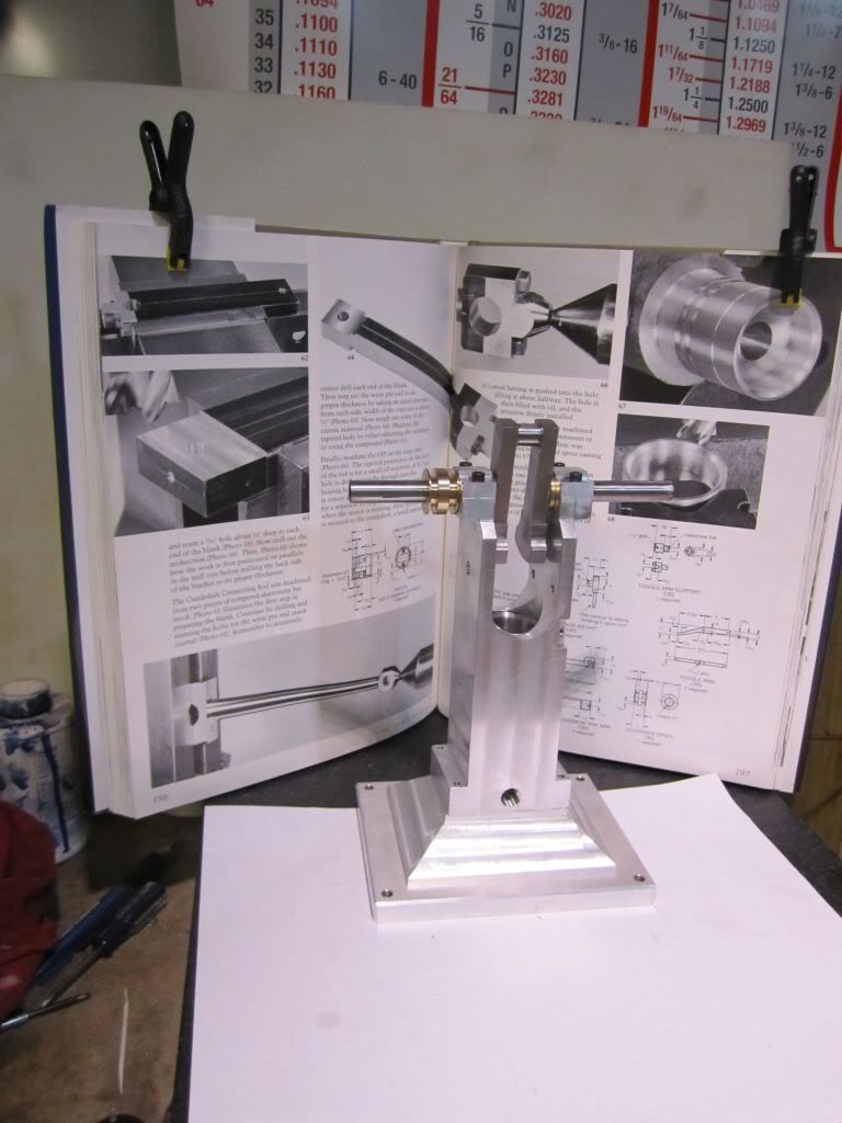
Sometimes a couple of short easy parts will do wonders for the ego after slogging through a bunch of difficult and critical components. Today I was in a light "git-er-dun" mood and wanted to knock out a few easy and quick to machine parts. In fact so easy to machine I might insult the intelligence of many on the board but I'll offer an apology now and post them anyway....
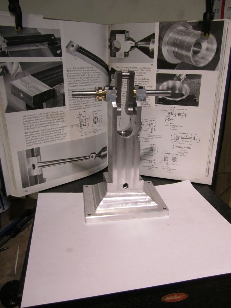
The first small project was the governor toggle arm support and the toggle arm. After this I made the cooling pipes and put them on the engine.
..... SERMON ALERT!!!....
Please understand that many of the parts will have to be fitted in the final process so what is displayed is STILL a work in progress. I could not imagine an engine going together with all of the parts made to the print and not have to do a good bit of "Fiddling" to get them to play in a concert. My opinion is.. All of the parts are just that; individual parts until the last phase where they will all be taught to "play together in concert.
.... END OF SERMON!!!....
The toggle arm consisted of some lathe work, then a second operation in the mill to cut the slot, then third operation to drill and tap the pivot and a fourth to mill the small flat for the setscrew in the body...
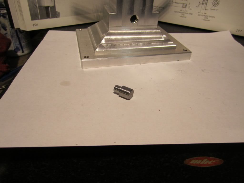
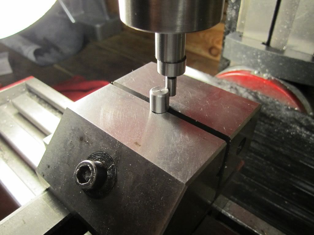
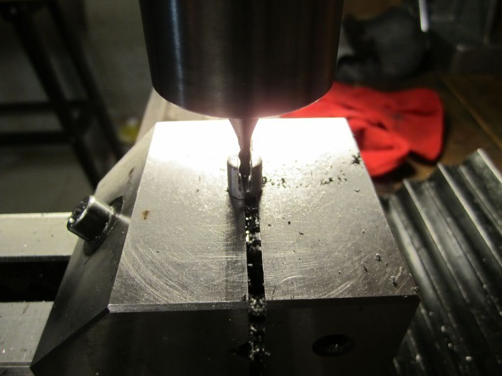
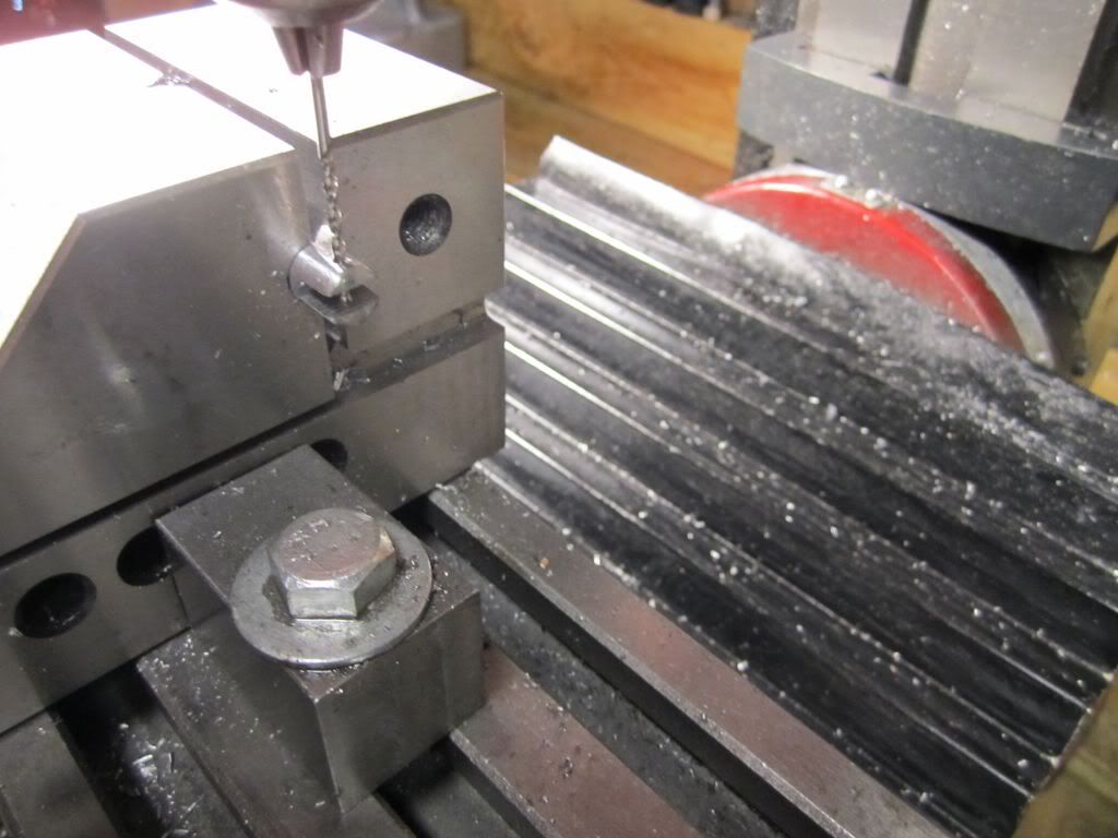
The next step is to construct the toggle arm... As with most of my builds, I do not have stock that is properly sized and I fire up my trusty shaper...
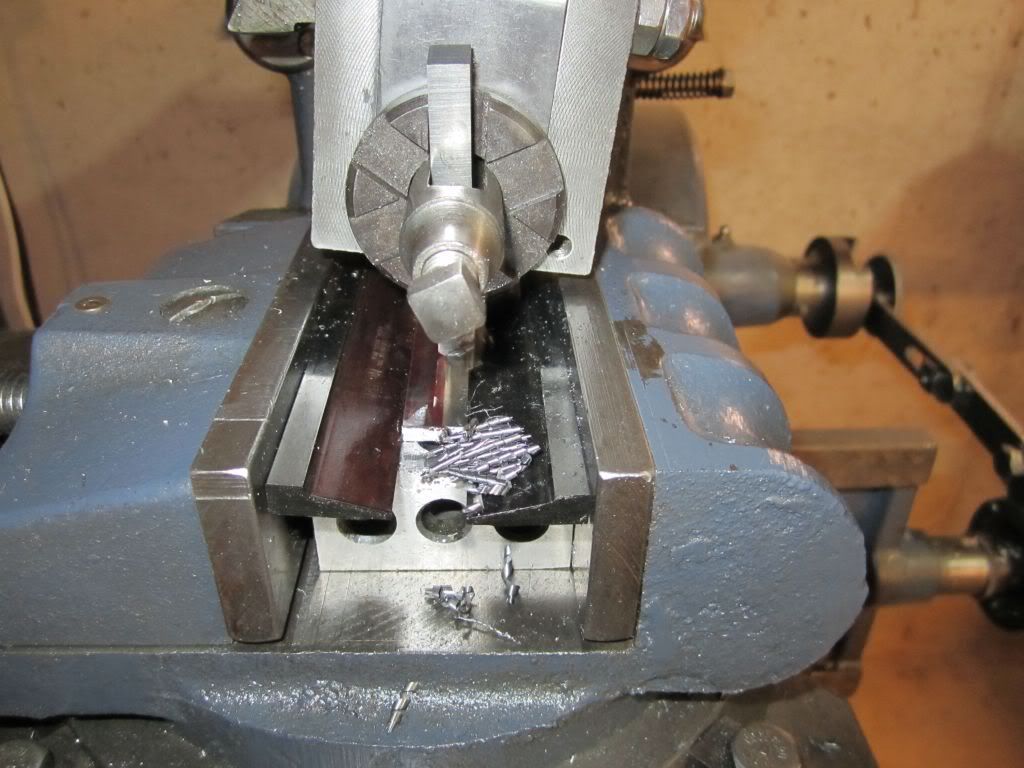
After this it is a layout, then sawing and filing to print dimensions...
The one variation I made to the plans is I use a 2-56 screw for the pivot. The plans call for a 1/16 cotter pin but I prefer to drill and tap and use a cap screw.
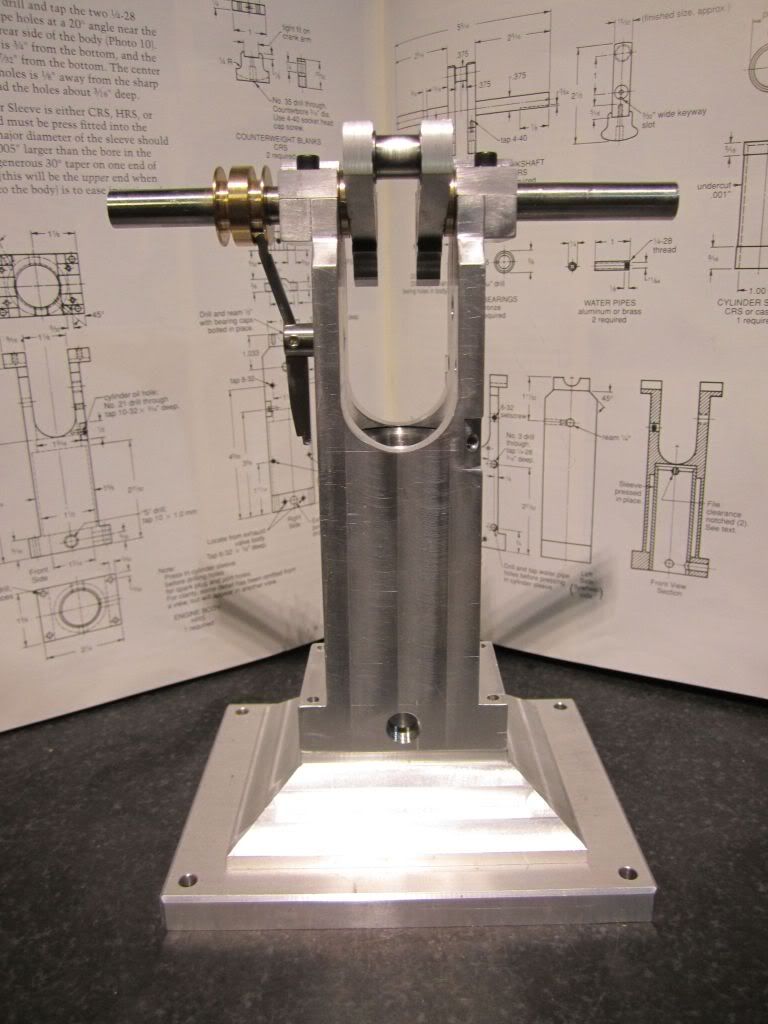
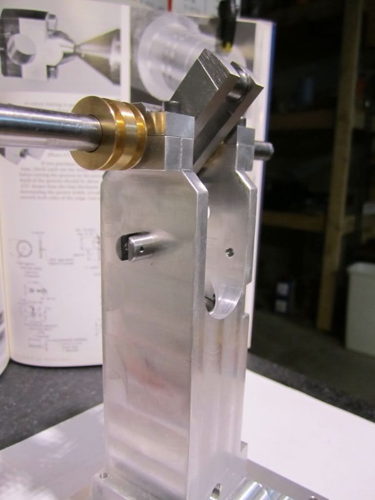
The other thing I did was to make the two water cooling pipes... It is as simple as using a die on a piece of 1/4 inch brass pipe and then parting it off to one inch...
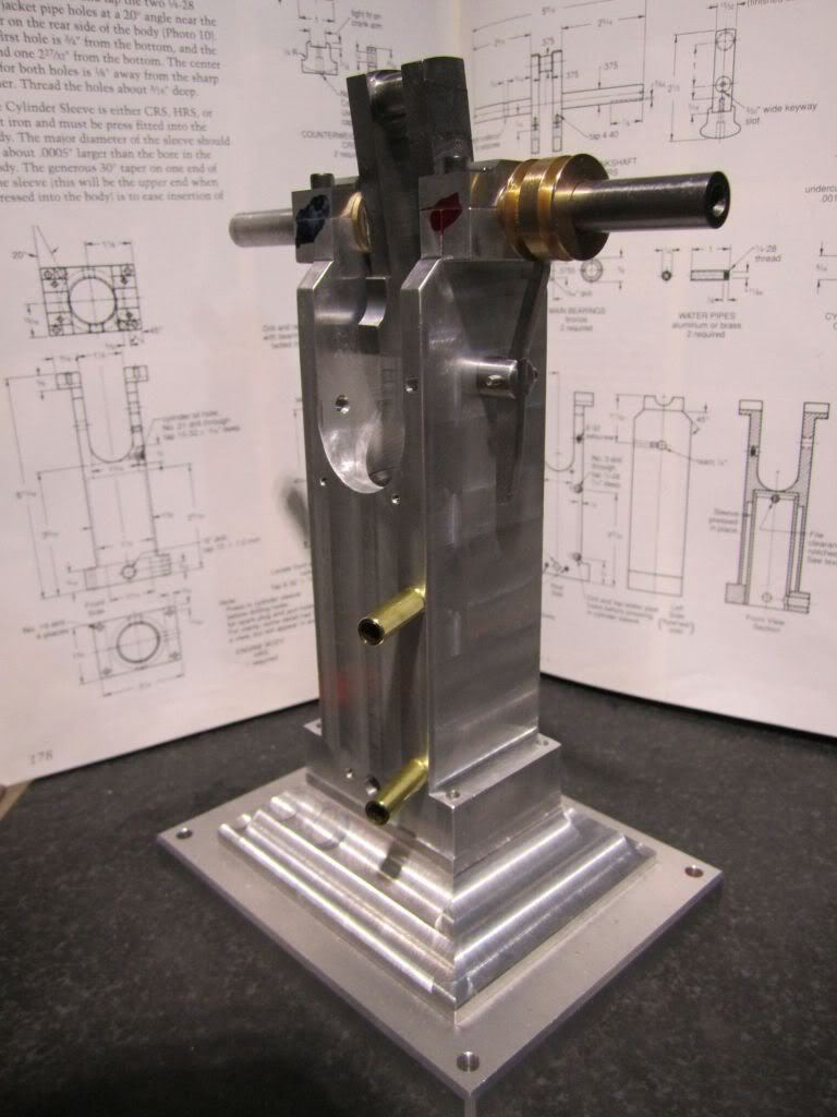
The first small project was the governor toggle arm support and the toggle arm. After this I made the cooling pipes and put them on the engine.
..... SERMON ALERT!!!....
Please understand that many of the parts will have to be fitted in the final process so what is displayed is STILL a work in progress. I could not imagine an engine going together with all of the parts made to the print and not have to do a good bit of "Fiddling" to get them to play in a concert. My opinion is.. All of the parts are just that; individual parts until the last phase where they will all be taught to "play together in concert.
.... END OF SERMON!!!....
The toggle arm consisted of some lathe work, then a second operation in the mill to cut the slot, then third operation to drill and tap the pivot and a fourth to mill the small flat for the setscrew in the body...
The next step is to construct the toggle arm... As with most of my builds, I do not have stock that is properly sized and I fire up my trusty shaper...
After this it is a layout, then sawing and filing to print dimensions...
The one variation I made to the plans is I use a 2-56 screw for the pivot. The plans call for a 1/16 cotter pin but I prefer to drill and tap and use a cap screw.
The other thing I did was to make the two water cooling pipes... It is as simple as using a die on a piece of 1/4 inch brass pipe and then parting it off to one inch...
Thanks for the thread! As a result I bought "Two Shop Masters" and received it last night. After a quick read through, interrupted by a few "your not listening to me" comments I can hardly wait to get started on some of the engines. I will definitely have this thread bookmarked.
Harold Lee
Well-Known Member
- Joined
- Apr 23, 2008
- Messages
- 236
- Reaction score
- 2
Thanks a bunch Rudy. I am enjoying the documentation process with the only drawback of having to wash the cutting oil off my hands to keep from getting it on my camera.
Danstir - I really like the book. There are a number of challenging engines in there as well as his Shop Wisdom book. Of all the model engine designers, Philip Duclos seemed to have the widest range. At one end is a very stark engine that was functional but not pretty IMHO. They would have a very unique mechanical feature like having no gears or his internal combustion oscillating cylinder. The other end of the spectrum would be very ornate decorative design like his Victorian. I have built his Odds & Ends design as well as working on this one and am very impressed. His instructions are very valuables as well and I would recommend following them on the difficult parts like the engine body and the crankshaft. If I can help please let me know. I know there are others on this board that have built this engine and I'm sure there is a wealth of experience available...
Danstir - I really like the book. There are a number of challenging engines in there as well as his Shop Wisdom book. Of all the model engine designers, Philip Duclos seemed to have the widest range. At one end is a very stark engine that was functional but not pretty IMHO. They would have a very unique mechanical feature like having no gears or his internal combustion oscillating cylinder. The other end of the spectrum would be very ornate decorative design like his Victorian. I have built his Odds & Ends design as well as working on this one and am very impressed. His instructions are very valuables as well and I would recommend following them on the difficult parts like the engine body and the crankshaft. If I can help please let me know. I know there are others on this board that have built this engine and I'm sure there is a wealth of experience available...
Hello Harold,
You are doing a great job of building and documenting your engine. Your Odd's & Ends engines are also beautifully done. I am really enjoying following along as well.
One tip that I can offer relates to the Governor Toggle Arm Support and the method that you used to find the center. Using an edge finder on a round part is not the best way to locate the center. It is unlikely that you will start out on the centerline, so there will be some degree of error. A better way is to use a dial test indicator, like a Starrett "Last Word" or similar type and sweep the diameter of the part, adjusting for the centerline.
Thanks for taking the time to share your work.
Kind regards,
Mike
Harold Lee
Well-Known Member
- Joined
- Apr 23, 2008
- Messages
- 236
- Reaction score
- 2
moconnor said:...snip...
One tip that I can offer relates to the Governor Toggle Arm Support and the method that you used to find the center. Using an edge finder on a round part is not the best way to locate the center. It is unlikely that you will start out on the centerline, so there will be some degree of error. A better way is to use a dial test indicator, like a Starrett "Last Word" or similar type and sweep the diameter of the part, adjusting for the centerline.
...snip...
Mike - thank you for your comments.... I did realize the issue of locating a round part but had not considered using a DTI... That seems to be the best way...
What I did was to locate the center and crank the table back and forth when the wiggler first indicated I was over center. At that point I indexed in to the center of the part and locked my axis. I then went the other way and found the edge. I took a reading and divided this by 2 and then indexed back that distance. It sounds complicated as I describe it and I am sure your suggestion is easier and probably more accurate. I'll certainly use that the next time.
Thank you again for taking the time to help me.
Best Regards,
Harold
mklotz
Well-Known Member
Actually, it's easy to accurately find the center of a circular piece with an edge finder if one uses the Osborne maneuver.
For the benefit of those unfamiliar with the procedure, here's the writeup that accompanies my program of the same name.
For the benefit of those unfamiliar with the procedure, here's the writeup that accompanies my program of the same name.
Code:
	In his book, "Home Machinist's Bedside Reader #2 (pg. 159)", Guy
Lautard describes the "Osborne Maneuver" for accurately centering round stock
in the milling machine using nothing more than an edge finder.

	It works like this. Accurately measure the diameter of the stock.
For description purposes, let's assume that the y axis is along the 12-6
o'clock line of the stock and the x axis is along the 3-9 o'clock line. Align
the edge finder by eye to the 3 o'clock position and locate the edge of the
workpiece. Now move by half the diameter towards the center of the stock along
the x axis. Now, use the y axis controls to find the edge of the stock near
the 12 o'clock position. Move half the diameter towards the center of the
stock along the y axis.

	Now do it again. Use the x axis controls to find the edge of the
stock near the 3 o'clock position. Move half the diameter towards the center
of the stock along the x axis. Use the y axis controls to find the edge of the
stock near the 12 o'clock position. Move half the diameter towards the center
of the stock along the y axis.

	As you repeat this procedure again and again you will approach the
center of the stock with ever increasing accuracy. (In mathematical terms,
the procedure converges to the center of the stock.)

	The question becomes, "How often do I have to do this?". The answer
is, "Probably fewer times than you think!". I wrote OSBORNE.EXE to examine
how fast the process converges. For example:

OSBORNE MANEUVER

Workpiece diameter [2] ?
Initial offset [0.1] ?

iteration: del1,del2,error= 1: 0.10000000, 0.00501256, 0.10012555
iteration: del1,del2,error= 2: 0.00501256, 0.00001256, 0.00501258
iteration: del1,del2,error= 3: 0.00001256, 0.00000000, 0.00001256
iteration: del1,del2,error= 4: 0.00000000, 0.00000000, 0.00000000
iteration: del1,del2,error= 5: 0.00000000, 0.00000000, 0.00000000
iteration: del1,del2,error= 6: 0.00000000, 0.00000000, 0.00000000

	Here we have a 2 (we'll say inch but units don't matter) diameter
workpiece and we initially aligned with an error of 0.1". That is to say, we
initially aligned by eye to the x axis at the 3 o'clock position with an error
of 0.1". If your eyes are that bad, you need better glasses! After the first
iteration we're still 0.1" off the x axis (del1), but we're within 0.005"
(del2) of being on the y axis. Our radial error (distance from the center of
the workpiece) is the root-sum-squared of del1 and del2 or 0.100126". On the
second iteration, del1 becomes the del2 of the previous iteration and that
puts us within 0.0000126 on the x axis. The iterations continue in this
fashion with del1 always becoming the del2 of the previous iteration.

	As you can see, even with a hideous initial error we've converged to a
nearly unmeasurable error after only three iterations. You can use the
program to experiment with other combinations of workpiece diameter and
initial error. Personally, I do it twice and don't worry about it.
Harold Lee
Well-Known Member
- Joined
- Apr 23, 2008
- Messages
- 236
- Reaction score
- 2
mklotz said:Actually, it's easy to accurately find the center of a circular piece with an edge finder if one uses the Osborne maneuver.
For the benefit of those unfamiliar with the procedure, here's the writeup that accompanies my program of the same name.
...snip...
This board is just incredible!!! - I did this one and a half times so I was not too far off... I think my little jog maneuver up front cut down on the coarse error. It is interesting how the center finder reacts to a curved surface over a flat surface. On a flat surface the finder goes over center and moves WAY OFF. On a curved part the center finder goes over center and as it moves on the curved surface it is not longer over center and will stop moving. It is a very "soft" indication and not nearly as obvious. now I am going to have to try this method as well just to satisfy my curiosity.
Thanks for the additional "rabbit hole" I'll have to traverse
Harold
It's real old school, But Zig Zag rolling papers in the blue package are almost exactly .001 thick. You can use these against your materials edge, Spin up your cutting tool and creep up towards that rolling paper using the table movements till it tears. If I'm using flycutters for example I hold the rolling paper with needle nose pliers just to keep my fingers safe. A dirt cheap edge finder. Another tip I got from the Machinist Bedside reader books.
Pete
Pete
Harold Lee
Well-Known Member
- Joined
- Apr 23, 2008
- Messages
- 236
- Reaction score
- 2
OK...OK Pete and Marv... you made me go downstairs to my personal private room and dig through my books... I have TMBR number 3.... I just love not only his shop wisdom but also his "laugh out loud" stories. Truly, Guy Lautard is to machinists what Patrick McManus is to the outdoorsman..
Similar threads
- Replies
- 0
- Views
- 800
- Replies
- 148
- Views
- 22K