Topsy Turvy Hit & Miss Engine Build

Home Model Engine Machinist Forum

Help Support Home Model Engine Machinist Forum:

This site may earn a commission from merchant affiliate links, including eBay, Amazon, and others.
Harold,
I guess were bastardising your thread, But if you don't have TMBR 1&2 you really should buy them. I'll agree 100% with your thoughts about these books too. If you enjoy those, You'll really like the Brownells "Gunsmith kinks" series of books. There's a huge ammount of really good info in them even if your not into guns.

For OT. Your latest engine pictures are looking real fine. I have no doubts Phil would be really happy with your efforts if he could see them. I'm thinking maybe a Project of the month once it's finished.

Pete
 
pete said:
Harold,
I guess were bastardising your thread, But if you don't have TMBR 1&2 you really should buy them. I'll agree 100% with your thoughts about these books too. If you enjoy those, You'll really like the Brownells "Gunsmith kinks" series of books. There's a huge amount of really good info in them even if your not into guns.

Pete

Pete - I am not worried too much about wandering a bit. I think that is the way my mind works as well. Sometime I wonder what is the larger item in my budget. Books or machine tools ;-)

I do plan on getting the two TMBR books. When I bought the #3 I thought it was a later release and contained everything 1 and 2 did... I'll also look into the Gunsmith book. I am not a gunsmith but in the early 70s I bought a Kentucky flintlock pistol kit which I completed and used to shoot it a bit. Other than that my current guns are a pellet rifle and a Daisy BB gun for my grandkids to plunk with.... So many things so little time... Thank you for your comments.

Harold
 
Today's work in the shop consisted mainly of getting stock to size for second operations. The first one was getting the stock to size for the intake and exhaust valve bodies. I am using aluminum on this one. I have used it on two of my IC engines and have never had a problem. If these were made for "real work" I would use CRS or cast iron. On one of my IC engines I made them out of brass and it worked just as well.

TopsyTurvyOct04-16.jpg


I am cutting my own gears so I also turned the gear blank for the crankshaft.

TopsyTurvyOct04-11.jpg


It was a turn, drill, ream, and part operation.

TopsyTurvyOct04-13.jpg


TopsyTurvyOct04-14.jpg


Somewhere in that block of aluminum are the two valve bodies. My job is to dig them out....

TopsyTurvyOct04-18.jpg


Since I am making my own gears, I am going to deviate from Phil's plans on the timing gear/camshaft. He used an off the shelf gear and adapted the cam to it. I am going to make it in one piece.... More on that later...

Harold
 
Today was a day of cutting stock to size and making gear blanks. I shaped, milled, sawed, filed, turned, parted, bored, drilled and reamed...

Here is the boring of the ignition cam recess on the cam gear. It was .032 deep and .812 in diameter.

TopsyTurvyOct05-1.jpg


Here are the two gear blanks, the two valve bodies and the cam roller arm blanks.

TopsyTurvyOct05-5.jpg


TopsyTurvyOct05-6.jpg


I am trying to decide if I am going to cut the gears on my vertical mini mill which I have always used in the past or cut them on my Burke#4 horizontal. The only issue I have on the Burke is I have to make some T nuts for the rotary table tailstock so I can turn the blanks on a mandrel. The advantage is I can start a cut and put the auto feed on and watch it do its thing. Hmmmm...
 
My vote? The horizontal for sure, Much more rigid set up and that power feed can't be beat. Your getting real close to that time consumeing job of doing the flywheel too. I'll be real interested in seeing your set up for that.

Pete
 
Pete - I think I agree with you. I have wanted to set it up but have just procrastinated. I think I'll bite the bullet and make the T nuts and get it set up... Watch this space...

Brian - Thank you so much. I really appreciate all of the encouragement. I have found that posting my progress does help to keep me focused and perhaps helps me to plan out the work better.

Harold
 
My project today was to make the cam roller arm. After layout, marking and drilling holes. I transferred the part to the mill to machine the part.

TopsyTurvyOct06-02.jpg


TopsyTurvyOct06-03.jpg


After cutting the basic "L" shape the next step was to mill the clearance on both sides of the part.

TopsyTurvyOct06-05.jpg


The slot was milled for the cam roller.

TopsyTurvyOct06-06.jpg


The work today took a bit more time due to my apprentice helper... I would like to caption this.. Hours to construct model - 600. Dollars spent on material - $375.00. Working with grandson in shop - Priceless!!!

TopsyTurvyOct06-08.jpg


All in all it was a successful day..

TopsyTurvyOct06-09.jpg


TopsyTurvyOct06-10.jpg


TopsyTurvyOct06-11.jpg


Next task is to radius the roller tabs and drill and tap in two places... Perhaps Tomorrow..


Today I completed the cam roller arm. It consisted of putting a radius on the part... I have found on small parts and soft materials, The best way for me is on the mill and rotate the part by hand moving the table about .005 at a time.

TopsyTurvyOct09-01.jpg


TopsyTurvyOct09-03.jpg


I then turned the cam roller and the bronze bushing on the lathe.

TopsyTurvyOct09-05.jpg


The next step was to tap the shaft hole and cut a 45 on each side per the print. I used a 45 degree block and then shaved off .050 on each side.

TopsyTurvyOct09-08.jpg


Here are the individual parts...

TopsyTurvyOct09-10.jpg


And here is the completed assembly...

TopsyTurvyOct09-11.jpg


The next step is the push rod anchor unit that will connect to this completed arm.

I am also rethinking my gears and would like some advice. The book calls for purchased gears and the crankshaft gear is steel and the cam gear is brass. I made both blanks out of CRS but I am second guessing myself and wondering if I should make another cam blank out of brass or cast iron and use that instead. Are there drawbacks for using steel for both? On my previous engines I have used steel for the crank gear and cast iron for the cam. No real science behind it though. Any comments would be appreciated.
 
In a real world working application, running steel on steel would eventually gall the gear faces and cause undue wear. For a model "demonstration" engine, you will be fine, just keep a bit of white grease on the gears so they slide rather than rub when mating.
 
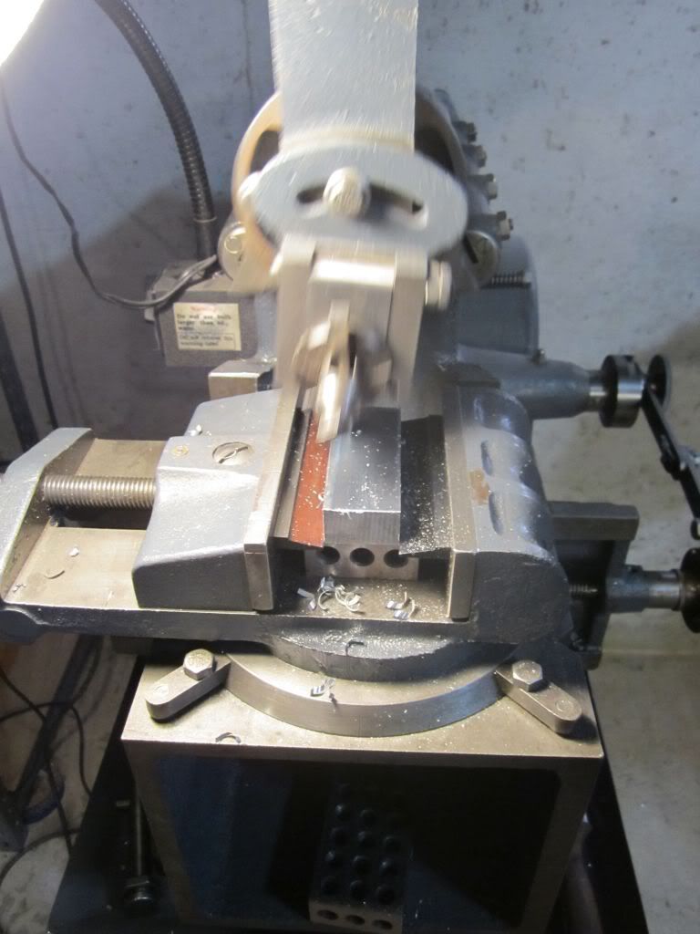
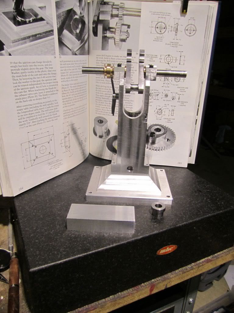
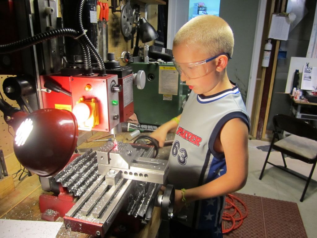
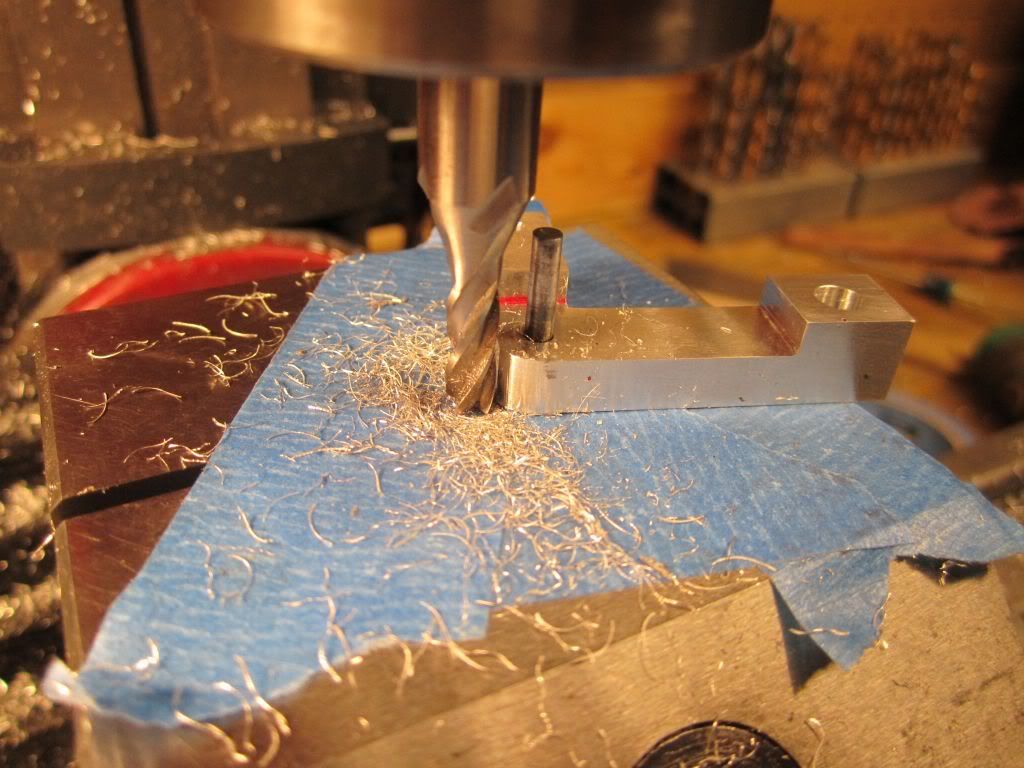
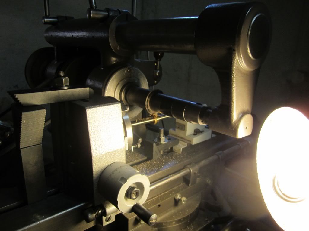
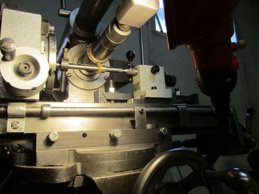
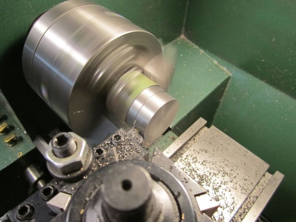
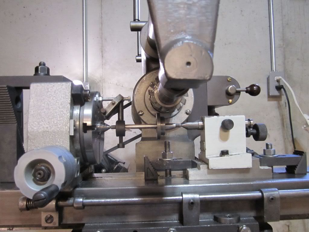
When I first started on this odyssey I decided to show my progress; warts and all. I think I have a tendency to want to show the pretty side of things and try to "bury" the ugly ones. I was faced with this dilemma today. I have taken off about two weeks to make a trip to the Northwest and just knew I should have resumed with something simple. A screw or a bolt or a shaft which would have eased me back into this but NO, I decided to jump right in and declare this Day the "Gear Cutting" day. I already had the blanks made and based on recommendations for some of you I set up my Burke and went to work. The first gear was the crank gear which had 22 teeth. There is no way a 22 tooth gear can be cut easily on a rotary table without a set of dividing plates. Even then on a 5 degree/turn (72 turn) rotary table the only plates that will work are 11 holes and 22 holes. With a 22 tooth gear a person might as well just make the gear instead of the plate since it will take the exact same mental gymnastics. With blank on the mandrel and the .071 tooth depth set I carefully start out...

TopsyTurvyOct24-02.jpg


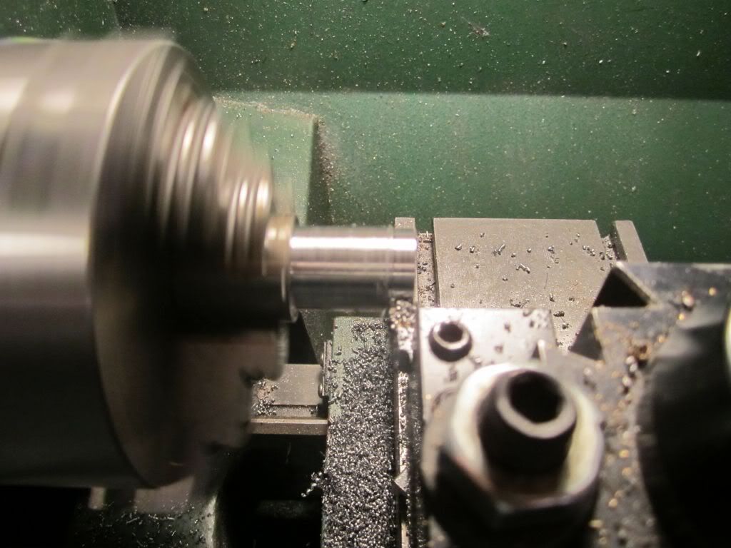
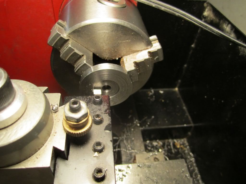
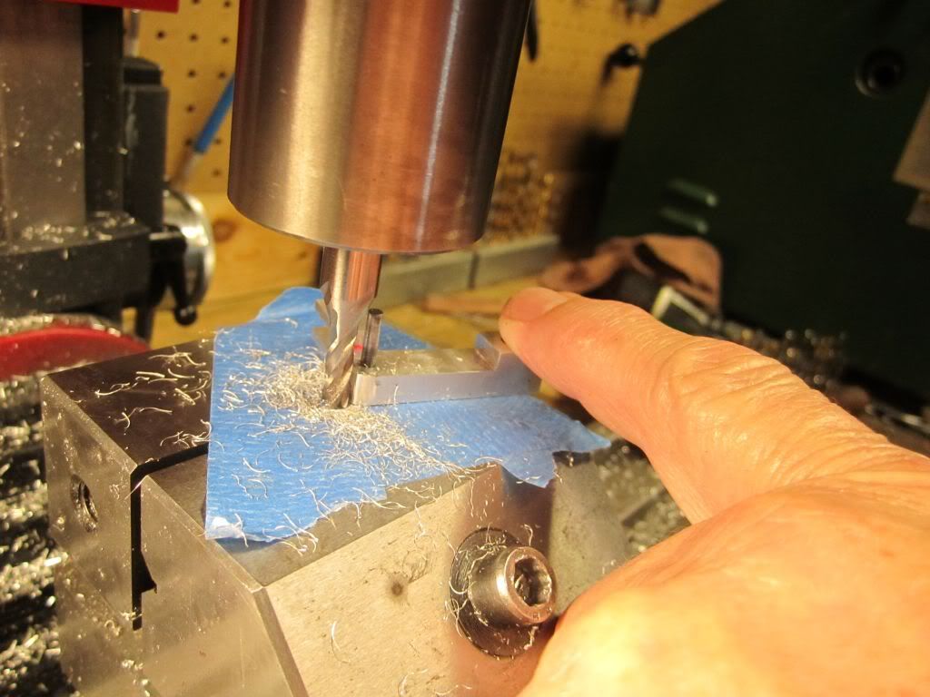
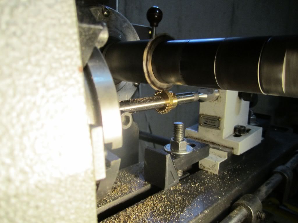
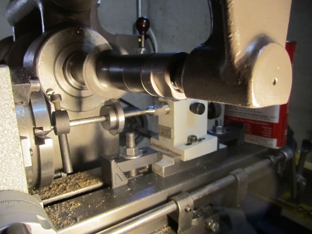
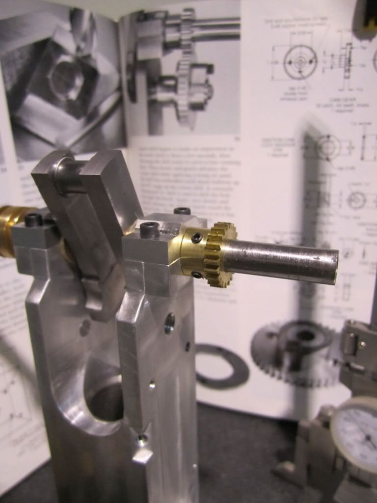
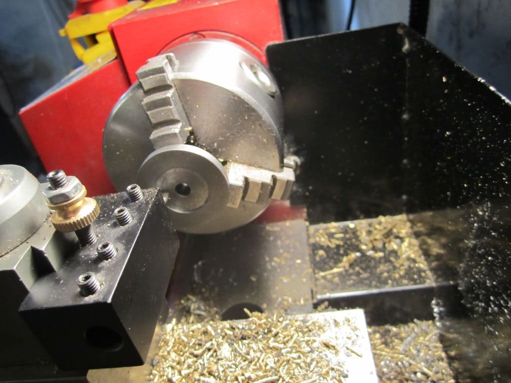
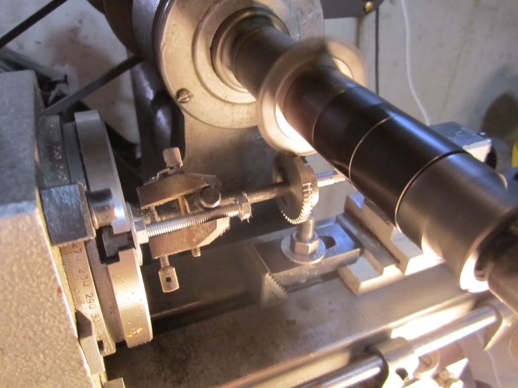
It actually went well but thinking about Brian's comment on using the same material on both gears could be a problem, but probably not, I decided to change the crankshaft material to brass. It only took about 20 minutes to turn another blank and run it through. Actually the mill was fun to work and I could do other things in the shop while waiting for each pass to complete. Just waited for the click as the auto feed would hit the stop and trip the lever.

TopsyTurvyOct24-10.jpg


TopsyTurvyOct24-13.jpg


TopsyTurvyOct24-15.jpg


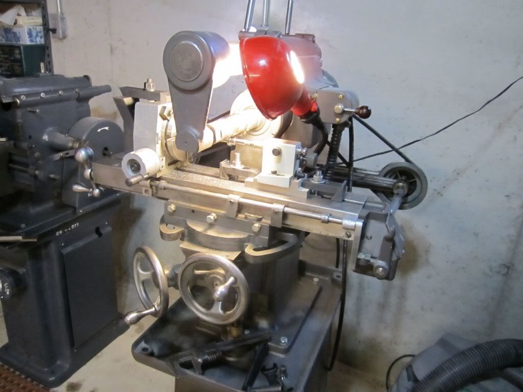
I just love watching these old machines!!!!

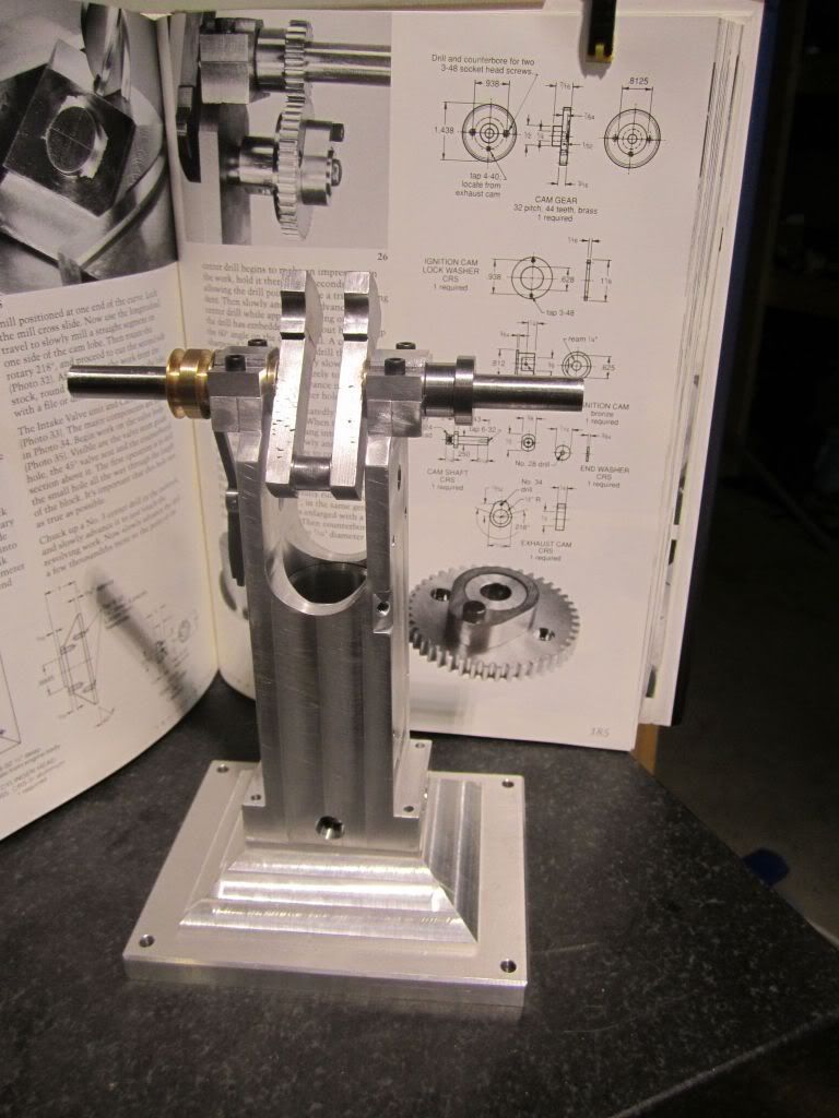
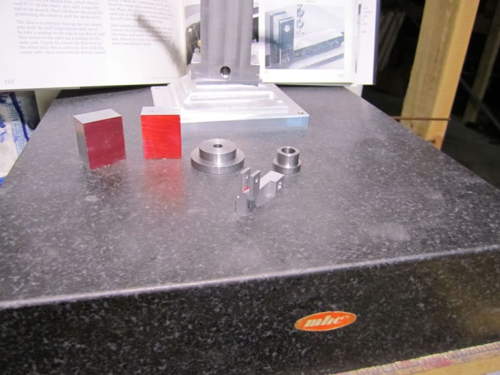
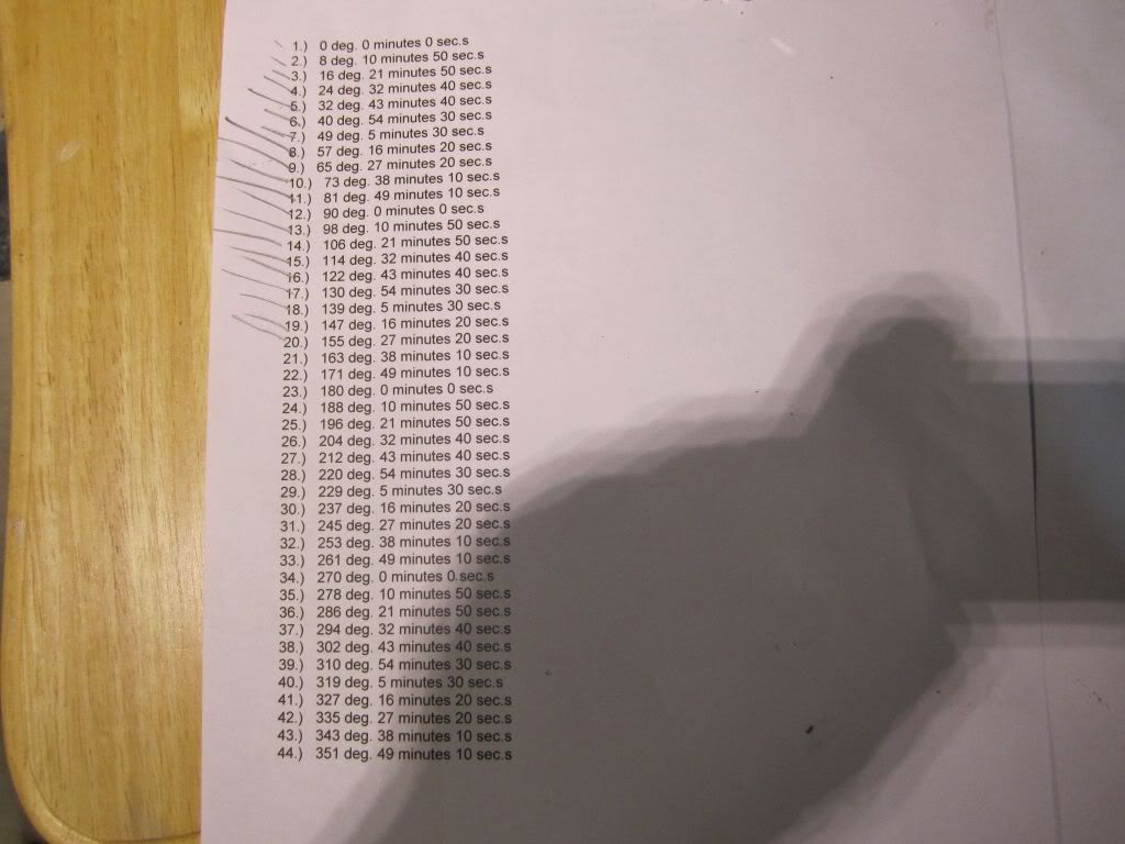
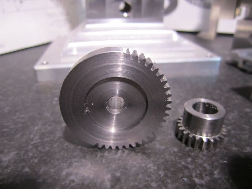
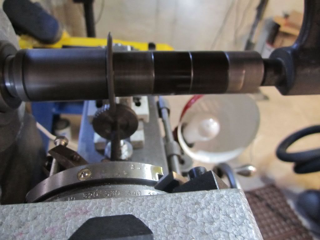
Next was the 44 tooth cam gear... With tables in hand I set out knowing this one would take twice as long..

TopsyTurvyOct24-21.jpg


TopsyTurvyOct24-16.jpg


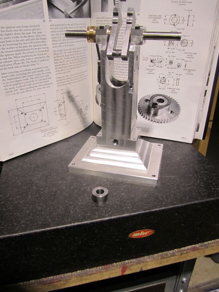
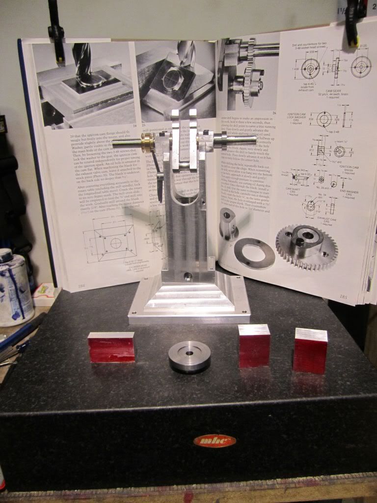
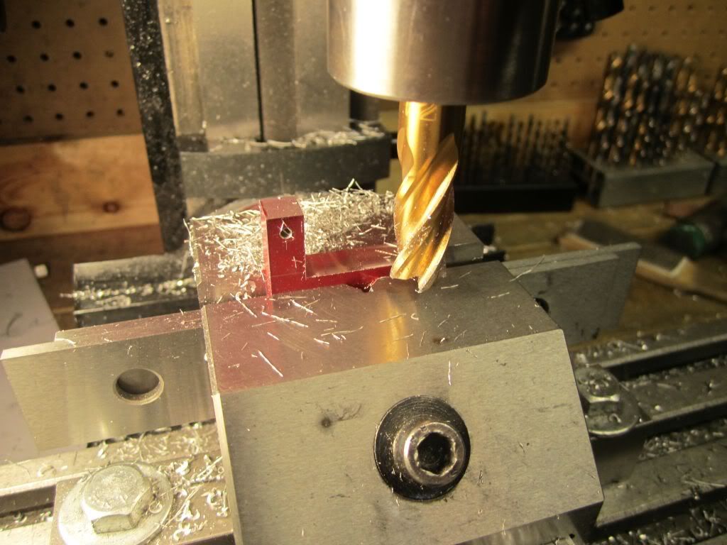
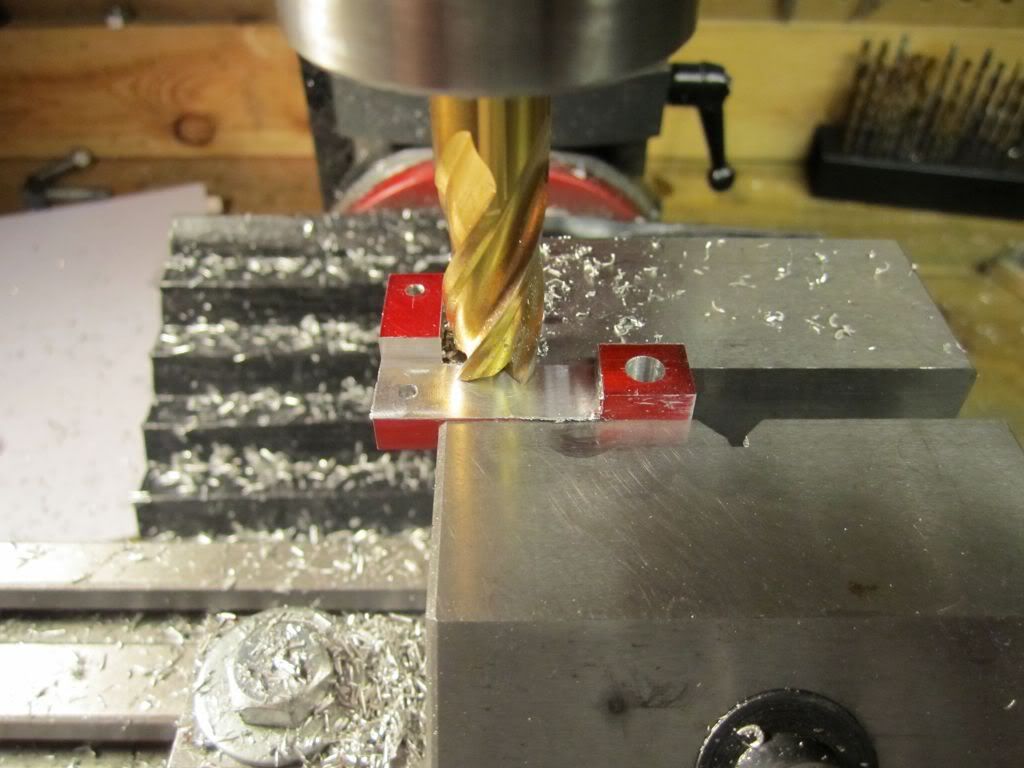
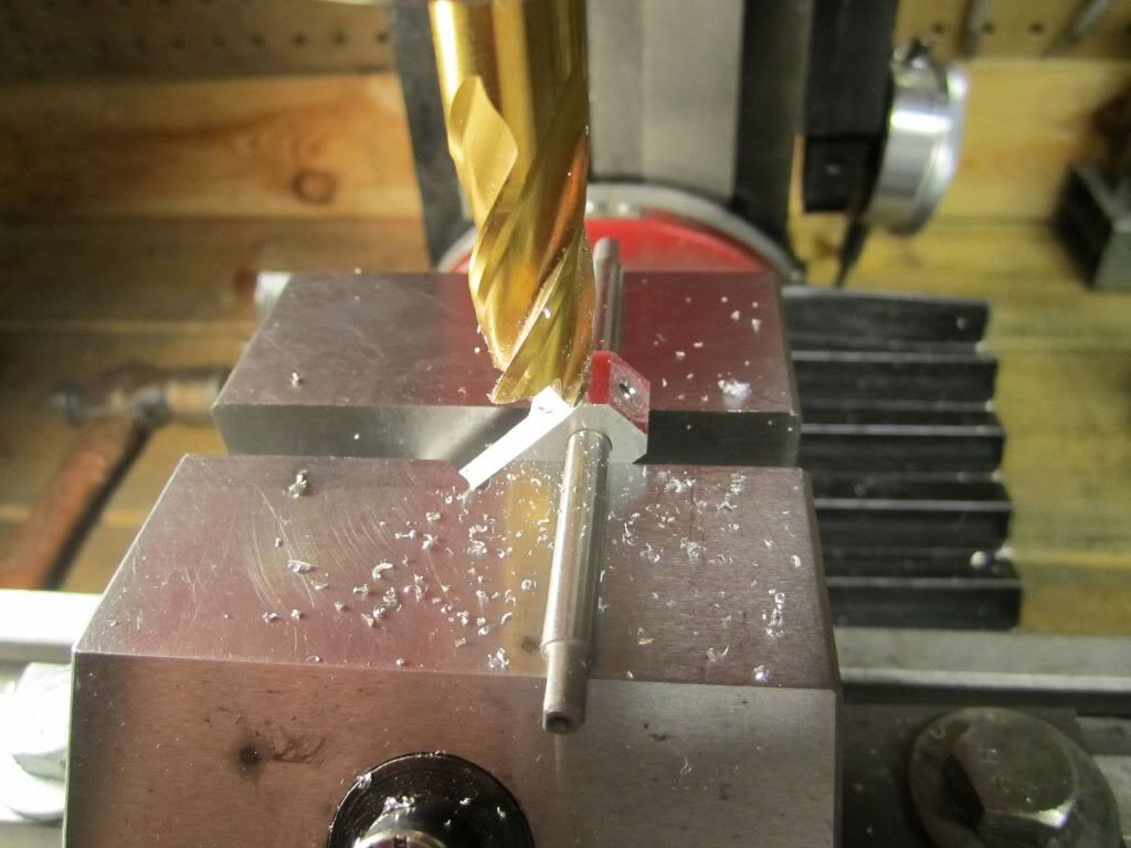
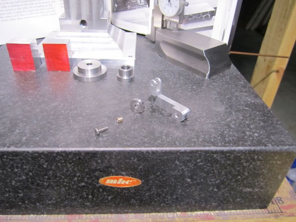
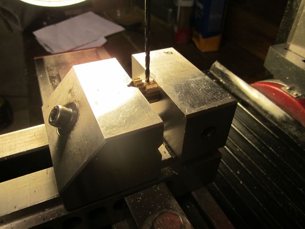
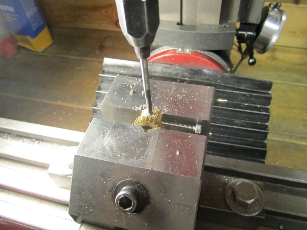
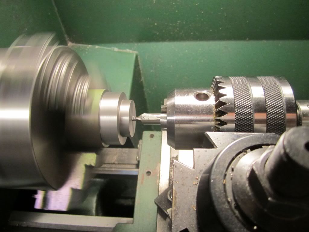
While that was taking place I decided to go ahead and tap the two set screws on the crankshaft gear...

TopsyTurvyOct24-18.jpg


Two places 90 degrees apart...

TopsyTurvyOct24-20.jpg


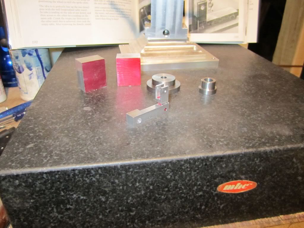
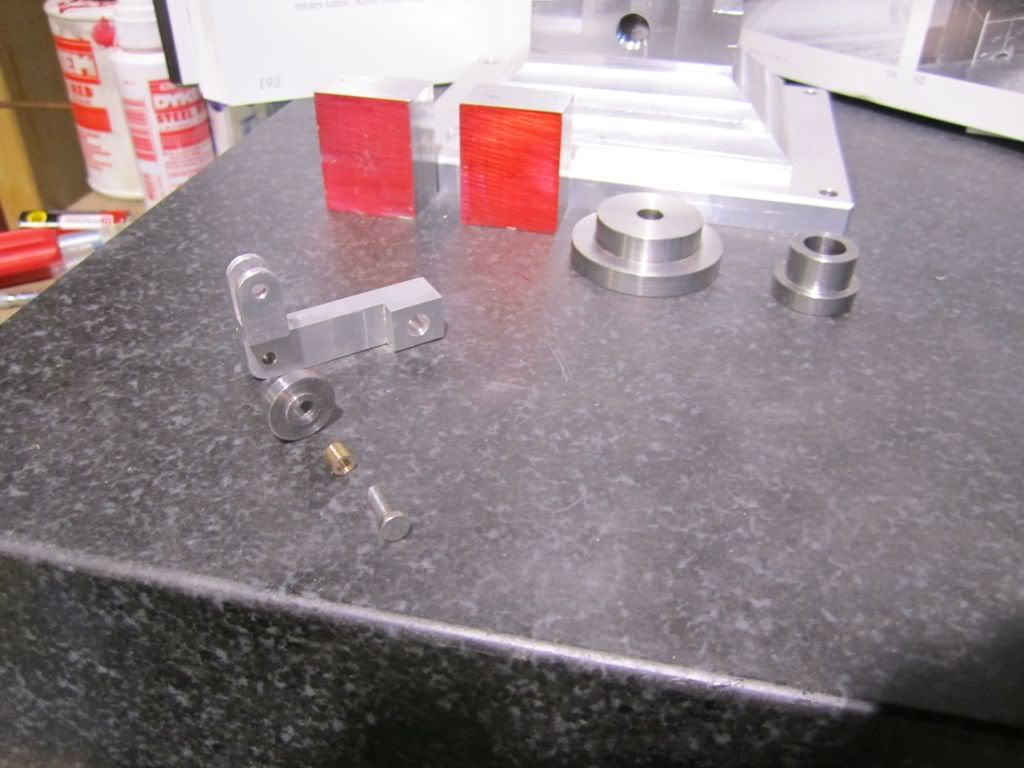
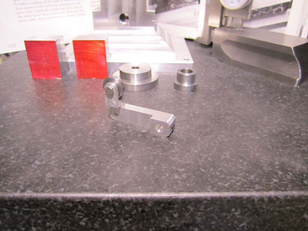
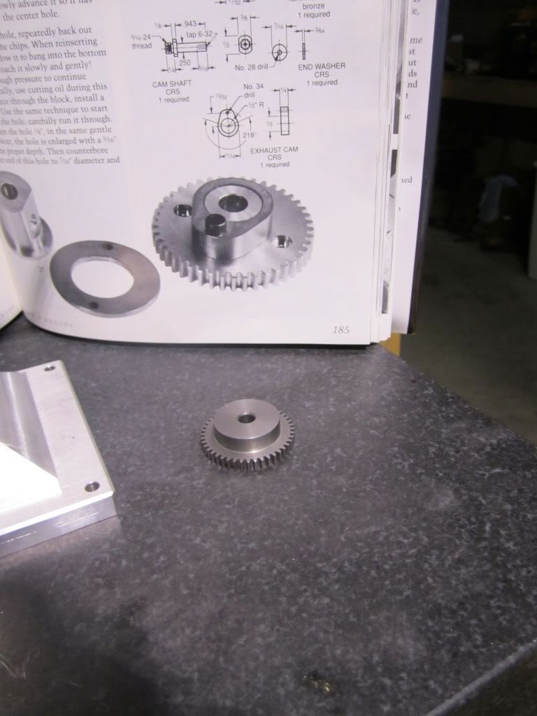
That came out pretty good and I was happy with the finished gear and glad I had made a brass one...

TopsyTurvyOct24-22.jpg


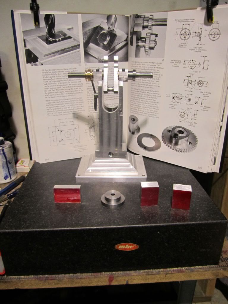
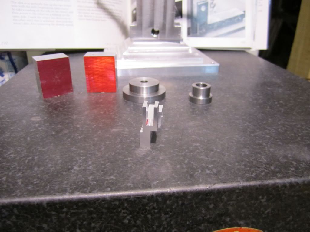
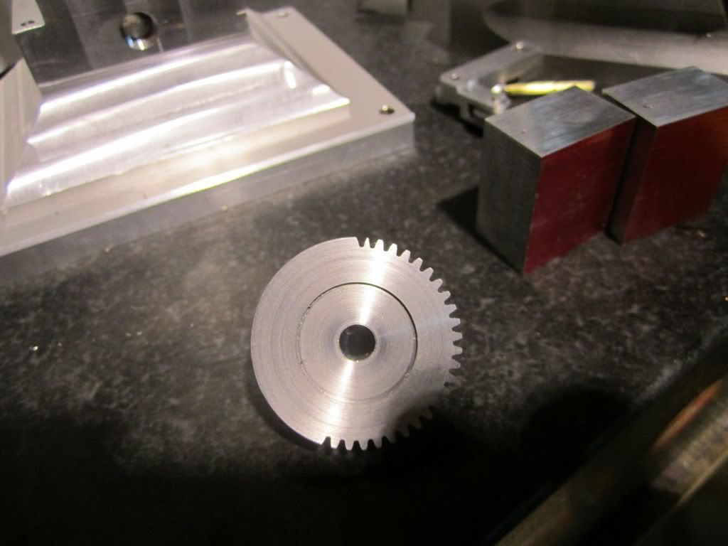
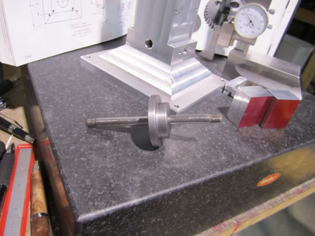
Somewhere in the back and forth and the reading of the step tables, something went terribly wrong... This is shown with the completed steel crank gear that I will not be using but it does represent some wasted effort.

TopsyTurvyOct24-24.jpg


TopsyTurvyOct24-25.jpg


So that is my day.. Don't know if I'll try to make another blank and cut it tomorrow of move on to something else and come back to it. Anyone need a 24 tooth half finished gear with two gimpy teeth in it? Well that is the ugly side of my progress...


Are 22 and 44 teeth absolutely essential for some reason?

With a 72:1 gear ratio (5 degrees per crank rotation), a 24 and 48 tooth gear pair would be a lot simpler to divide out - less chance of error.

360/24 = 15 => 3 crank turns per gear tooth

360/48 = 7.5 => 1.5 crank turns per gear tooth
 
thanks for showing your mistake..................i was beginning to wonder if you ever made any. ;D

the whole project and the write up look excellent :bow: thanks for the effort, so all of us can follow along.


chuck
 
It's not a totall loss, You learned what not to do next time. Just think, That could have been something with a really high tooth count and it gets ruined on the last tooth. It's not a matter of IF you'll make a mistake when cutting gears. it's exactly WHEN your going to do it. The replacment gear will be easy. You already know what to watch for. Marv does bring up a good and easier way to do things while still giving you that same 2-1 gear ratio to fit within your 72-1 R/T gearing. Maybe it's redundant at this point, But cast iron for the gears would work well with both of them using the same material.

Nicely shown mill set up. It's hard to beat a horizontal mill for work like this. Your Burke mill looks like it's a semi universal type with the capability to pivot the table in a horizontal direction. You've selected and bought some very desireable machine tools.

I could be wrong, But going by your pictures. The shaft dog should be fixed to that peg sticking out from your rotary table using something like a semi hard wire as tight as you can get it. This won't allow any rotation in the oposite direction of your gear blank. Possibly there's something to do this that I've missed in your pictures.

Pete
 
mklotz said:
Are 22 and 44 teeth absolutely essential for some reason?

With a 72:1 gear ratio (5 degrees per crank rotation), a 24 and 48 tooth gear pair would be a lot simpler to divide out - less chance of error.

Marv - You are correct and if I had thought that far ahead when I was drilling out the main base I probably could have done that and made the adjustment. The engine body was drilled and tapped for the cam gear which was located 1.033 from the centerline of the crank. At this point I am painted into a corner.. The 22/44 setup distance is 1.031 and the 24/48 would require 1.125

pete said:
SNIP...
Maybe it's redundant at this point, But cast iron for the gears would work well with both of them using the same material.

Nicely shown mill set up. It's hard to beat a horizontal mill for work like this. Your Burke mill looks like it's a semi universal type with the capability to pivot the table in a horizontal direction. You've selected and bought some very desireable machine tools.

I could be wrong, But going by your pictures. The shaft dog should be fixed to that peg sticking out from your rotary table using something like a semi hard wire as tight as you can get it. This won't allow any rotation in the opposite direction of your gear blank. Possibly there's something to do this that I've missed in your pictures.

Pete

Pete - On my previous hit & miss engines I did make the cam gears out of cast iron. I have a chunk and might go ahead and use that when I make my next one. CI is messy but I like cutting and milling it.

I bought my Burke on eBay and drove down to Alabama and brought it home in my truck. I spent about 9 months disassembling it, stripping the old paint off and then repainting it and rebuilding it. I really like having the universal table but have not used it yet. I also have a vertical head attachment but there in not much headroom due to the additional height of the universal table.

Good catch on the dog. I initially put a small machinist clamp on it but it got in the way. Each time I indexed it I made sure there was contact but on the next one I'll use some aviation safety wire. Thanks for the tip.

chuck foster said:
thanks for showing your mistake..................i was beginning to wonder if you ever made any. ;D

the whole project and the write up look excellent :bow: thanks for the effort, so all of us can follow along.

chuck

Chuck - I appreciate your encouragement very much. Regarding mistakes, let me assure you I make many of them; fortunately not all of them are show stoppers.
 
Really enjoying your thread Harold. I've been wanting to build one of these and you've inspired me to make a start.

looking forward to seeing more progress :bow:

Steve
 
Harold Lee said:
Marv - You are correct and if I had thought that far ahead when I was drilling out the main base I probably could have done that and made the adjustment. The engine body was drilled and tapped for the cam gear which was located 1.033 from the centerline of the crank. At this point I am painted into a corner.. The 22/44 setup distance is 1.031 and the 24/48 would require 1.125

Yes, I was afraid that might be the case. Ah, well, keep it in mind for the next one.
 
Today was one of those "buck up little soldier" days... I took to heart what Marv, Pete, Brian and others said and moved forward... Yes I do take to heart what the comments are and I hope all of you can see a little of yourselves in my work. Thank you very much for your constructive criticism.
This morning I decided to "soldier" ahead and complete the cam gear... Based on Brian's suggestion I decided to make the cam gear out of cast iron...

TopsyTurvyOct25-04.jpg


TopsyTurvyOct25-05.jpg


It took only a few (20) minutes to cut and make the CI blank for the cam... After cutting and turning all of the diameters I did a second operation for the ignition point recess...

TopsyTurvyOct25-06.jpg


It was time to continue with the pressing in of the mandrel and mounting it on the mill..

TopsyTurvyOct25-07.jpg


TopsyTurvyOct25-08.jpg


Pete - Please note that I secured the dog to the table with a clamp... Thank You.. In my first attempt I tried to put it on the outside and it got in the way. While I do not like to think about this, it could have contributed to my Oh S***T!!! on my first attempt.

TopsyTurvyOct25-18.jpg


TopsyTurvyOct25-14.jpg


With all that being said. I completed the cutting of the 44 teeth and I am well pleased with it...

TopsyTurvyOct25-21.jpg


The next step is to cut the cam on the gear.... Notice from the drawing that this is meant to be two separate parts that are screwed together. This is due to the fact that Phil specified a commercial gear and made the cam to mate with it. If I mess up the cam cutting my fallback position is to turn the lobe down and make a separate cam to bolt on as the drawing depicts... More to follow...


Triple good job. The second one is more frustrating because of the "Do over" but it's always easier and better. Yours looks the equal to any commecial ones I've seen and way better than some lathe change gears I've also seen.

Apologys for the "I should have thought of this before". But it may have been better to cut your cam first and then the teeth. But I don't think you'll have any problems. Did you get the info I emailed?

Pete

 
pete said:
Apologys for the "I should have thought of this before". But it may have been better to cut your cam first and then the teeth. But I don't think you'll have any problems.

Pete

Pete - I had considered cutting the cam first but I would have to tear down my gear cutting set up since I need my rotary table to cut the cam. After that I would have to set it up again to cut the gears. If I mess this one up and cannot recover, I'll make a blank and cut the cam first since the RT will already be in the vertical mill.
 
Back
Top