Topsy Turvy Hit & Miss Engine Build

Home Model Engine Machinist Forum

Help Support Home Model Engine Machinist Forum:

This site may earn a commission from merchant affiliate links, including eBay, Amazon, and others.
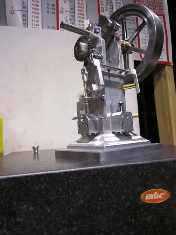
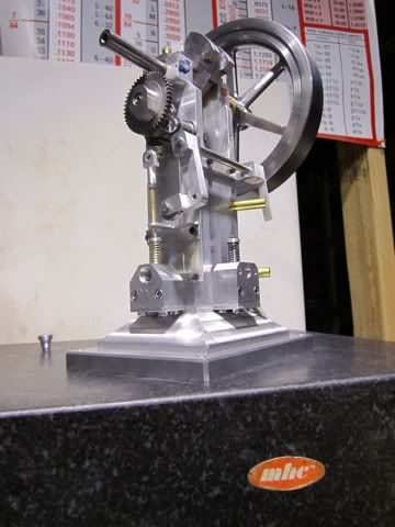
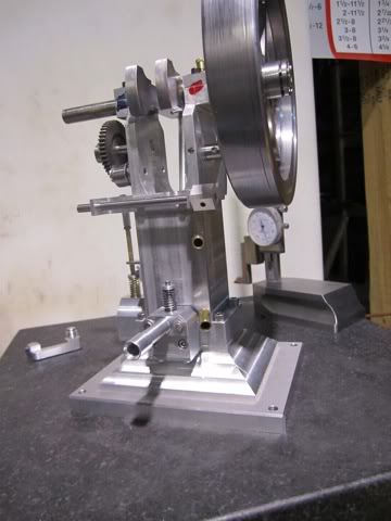
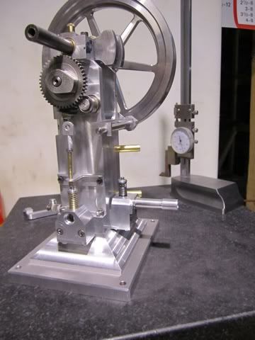
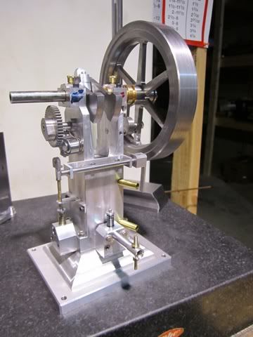
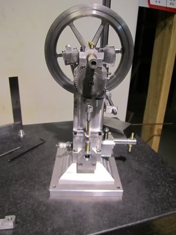
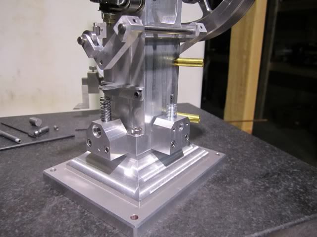
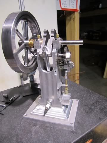
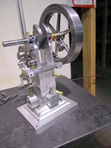
Rudy, Doc and Jeff - I appreciate your encouragement. I am also getting anxious to see it run but that will wait a few more days (weeks?). One comment and a question regarding the collet. There are three holes that are tapped on the flywheel for tightening everything up. There are three holes that are tapped on the collet for removing the flywheel. While the following step would be purely cosmetic I was wonder if the three tapped holes should have short bolts put in them. If I wanted to remove the collet the three dummy bolts would be removed and the three longer bolts put in their place.... Pondering...

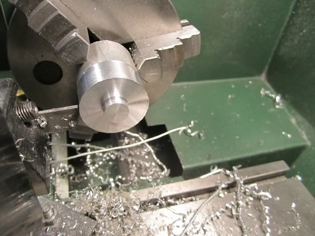
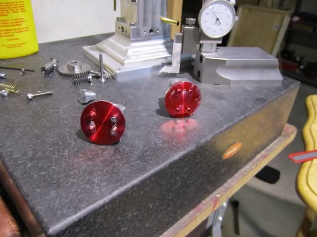
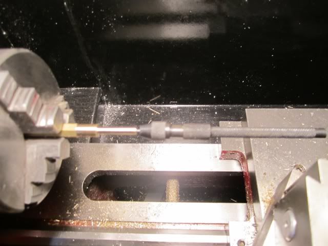
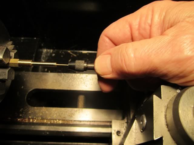
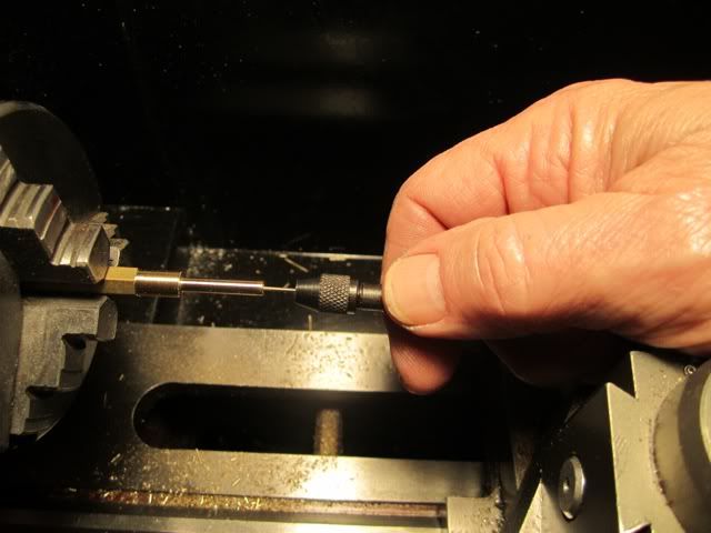
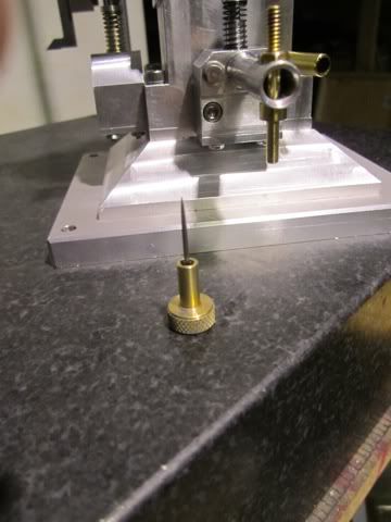
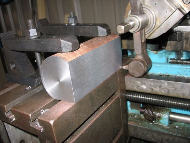
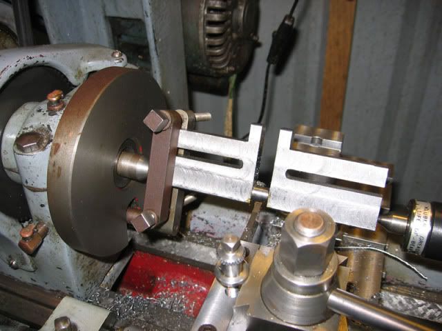
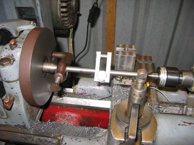
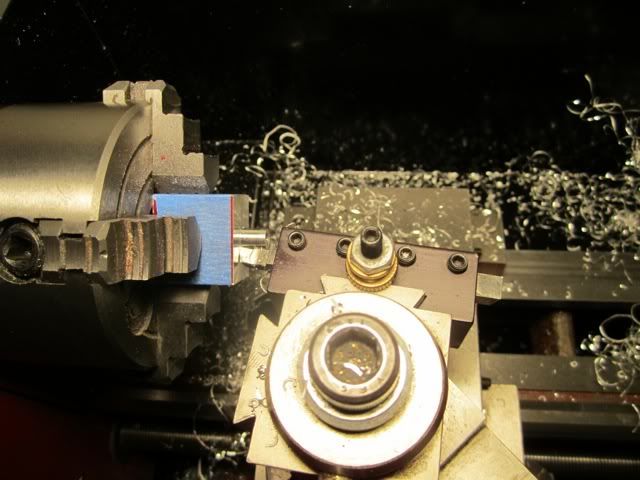
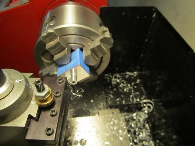
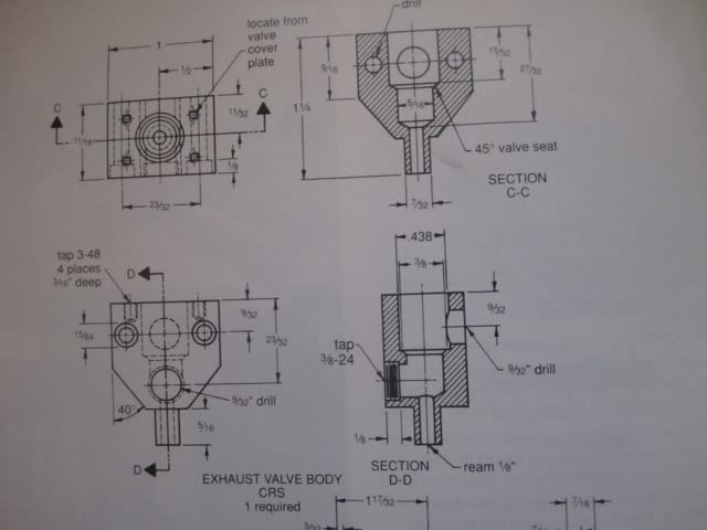
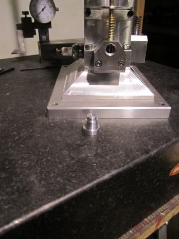
Today I was able to complete the valve bodies. The first step was to put a .125 mandrel in the valve stem hole and use that as a reference for truing up the part in the four jaw chuck.
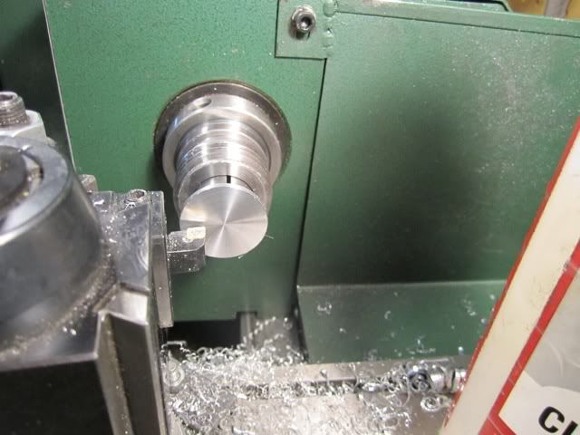
After that the valve guide was turned to dimensions.

file-161.jpg


file-162.jpg


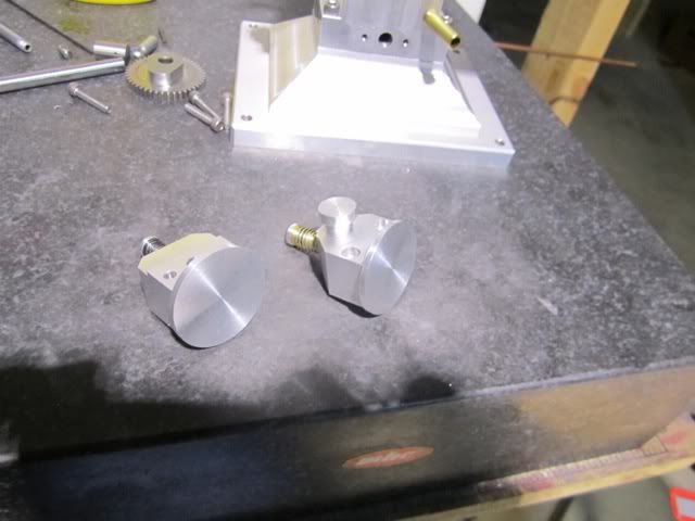
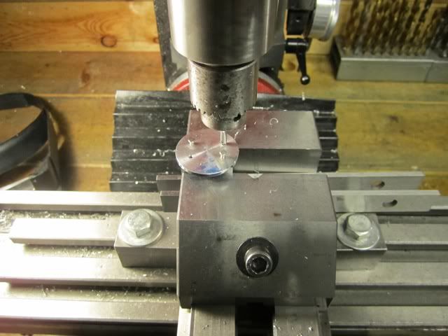
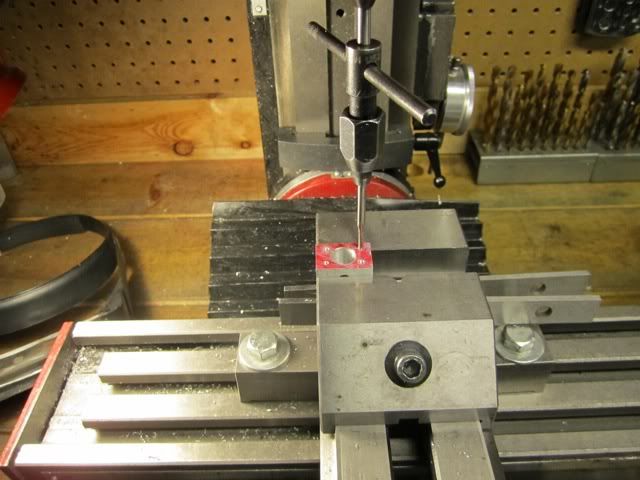
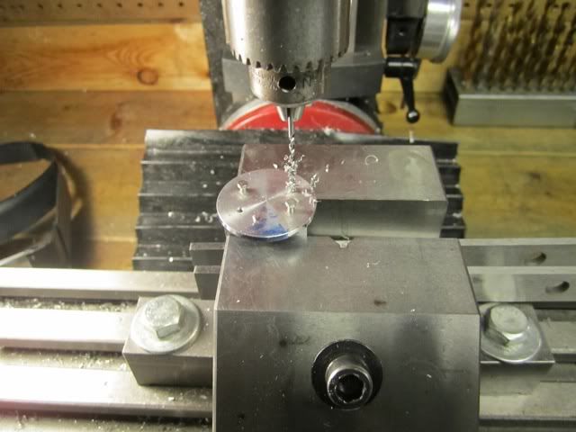
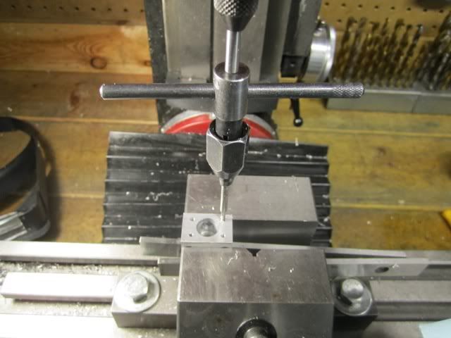
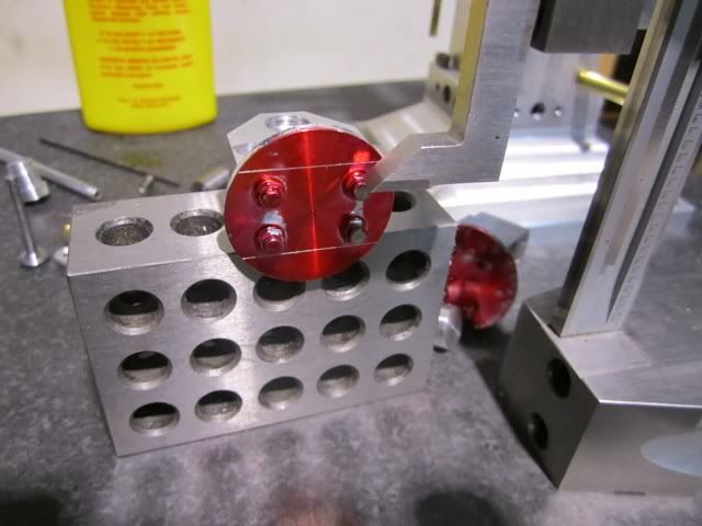
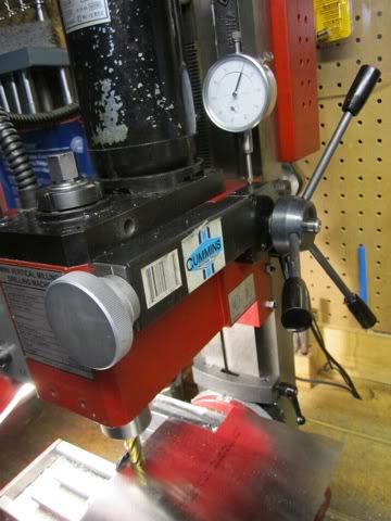
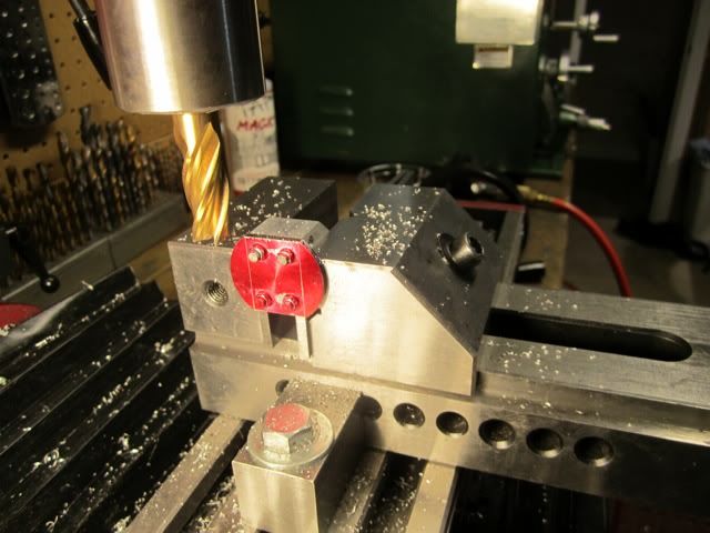
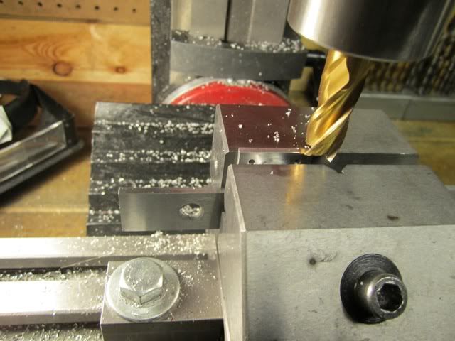
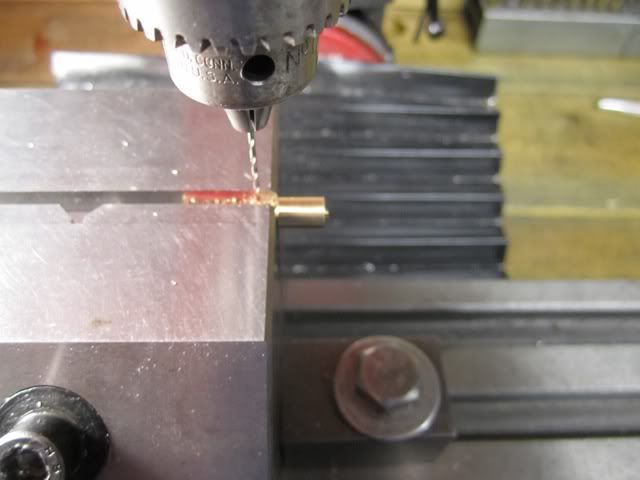
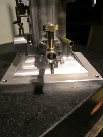
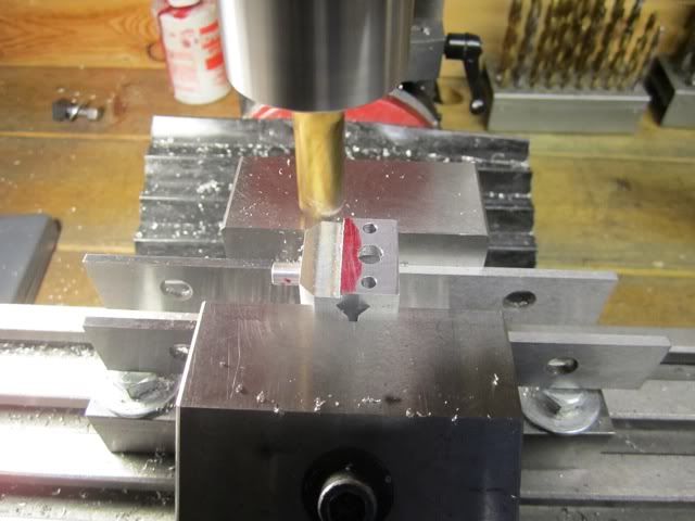
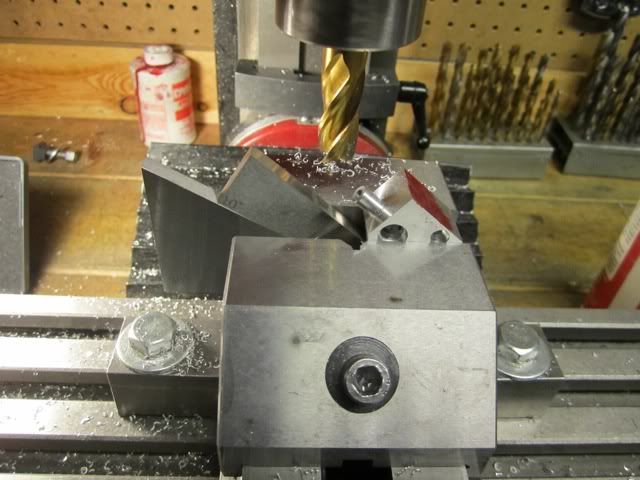
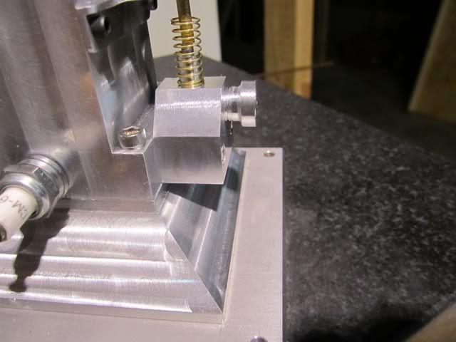
After this was completed the part was moved to the mill to locate, drill, and in some cases tap the holes.

file-163.jpg


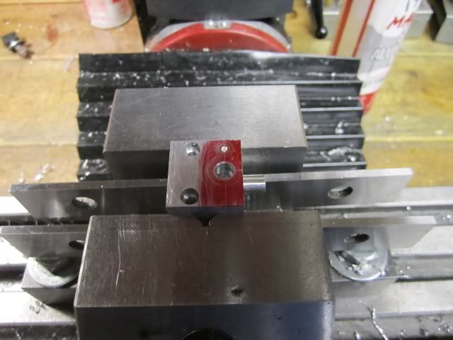
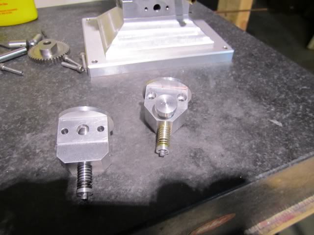
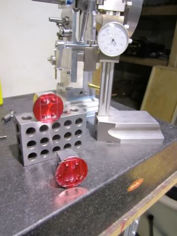
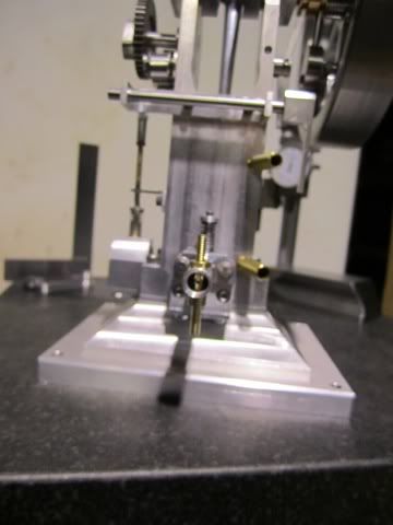
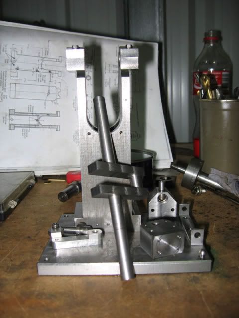
After all of the holes were completed the part was milled to final dimensions and the sides were beveled.

file-164.jpg


file-165.jpg


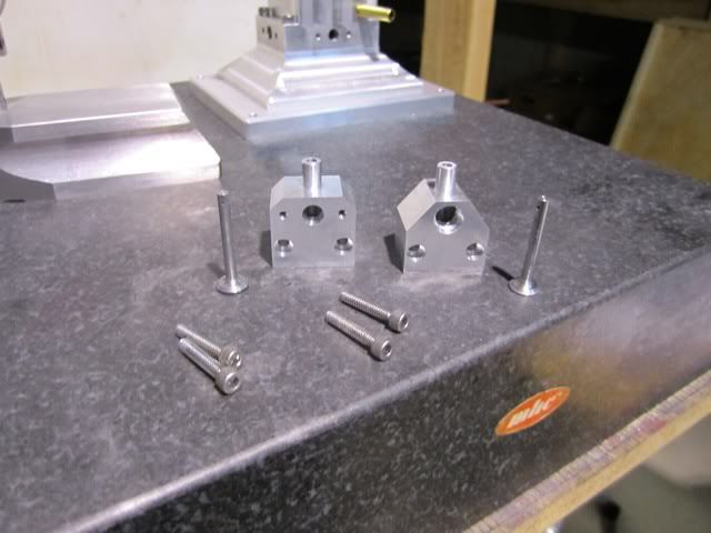
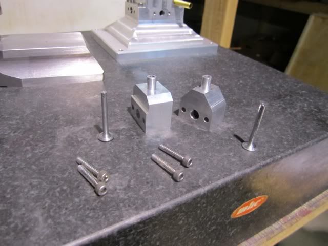
At this point the valve bodies are complete. The remaining work on this part of the engine is to make the valve keepers and the valve cover plates.

file-166.jpg


file-167.jpg


All in all a pretty good day...

file-169.jpg


file-171.jpg


file-172.jpg
 
That's really coming along nicely!
 
Absolutely. That's good steady progress you've got going there Harold. And looking great!

Steve
 
Looking great Mate
Pete
 
Many thanks for the encouragement and kind words. Knowing someone is watching over my shoulder makes me want to be more careful and methodical in my work. I appreciate it.

>>>>> ERROR IN TOPSY TURVY DRAWINGS - PLEASE READ IF YOU ARE BUILDING THIS ENGINE <<<<<<

Rant on!!! Last night I was reviewing my work and looking at what was next and realized that there is an error on the drawings from the book. I have to imagine there has been many (dozens? hundreds?) of these engines made and I am sure others have run across this as well. I have to say I am very disappointed in Joe Rice, the editor and Village Press. I think the book is out of print now, but I sure would have appreciated an errata sheet when I purchased the book a number of years ago. Now to be fair to Joe, I know Philip Duclos sent his drawing to Joe on napkins and sketches on odd shapes of paper. As Joe once told me, the quality of Philip's designs, photographs and editorial made the fact that they had to hire a draftsman to redo all of his drawings was a small price to pay for his work. However I have to believe in the years following there wasn't someone that brought this to their attention. Rant off!!!

file.jpg


When I was making the exhaust valve body, the hole for the muffler was specified as a 9/32 (.281) drill yet the tap called out was a 3/8-24. The problem is a 3/8-24 tap drill for 75% thread ( I use in aluminum) is a 'Q" drill (.332). This should have thrown up a red flag but I looked at the print and after convincing myself (deluding myself?) that the thread was only 1/8 inch deep, I went ahead and drilled it with a "Q" to a .150 depth. In order to get enough threads in 1/8 to a bottom, I ground a tap flat and made the three threads (24 tpi/8). Imagine my surprise when I looked several pages later at the muffler drawing and saw the thread called out there was a 5/16-24. The tap drill called out for this is in fact a 9/32 drill!!!! DOH!!!

file-1.jpg


Not wanting to scrap the valve body, I am going to try to salvage this by making the muffler pipe diameter 3/8 instead of 5/16. The problem may be that the 3/8-24 thread will bottom out and might be a source of a leak in the exhaust. If it fails, then after I pitch a huge fit, I'll remake the valve body, a little wiser, but with a 5/16-24 thread. If anyone has any suggestions, please let me know as I am really open to anything at this point except a gob of JB weld.

 
Frazer - This is really an enjoyable and challenging project. While I am not a machinist by profession, it has taken me to the limits of my capabilities. I think you would enjoy the build.

I think I might have a way to move forward with my exhaust/muffler problem. I turned up a couple of test nipples to see what they looked like and the one that seems the most promising is this one:

file-174.jpg


It has a shoulder on it that is 9/32 which is the diameter of the clearance drill that was called out. This will (I hope) help to locate the muffler and give it a seat which will prevent any leakage of the exhaust.

file-175.jpg


It seems to seat firmly but only time will tell. The two parts that I am not going to make before my first run is the muffler and the drip oiler. These are not required for the engine so I will defer those until after run-in. This will however require me mixing 2 cycle oil in with the gas to provide lubrication in the cylinder and piston area.
 
Hi Harold,Many thanks its a build I have wanted to do for a while and was fortunate recently when i was given a copy of the book ;D.Just finished Little Blazer and it was a nice build no probs.I have a few toy boats to finish then its on with Topsy.
Best wishes Frazer
 
Harold, my build is a fair way behind yours, but the one thing I had made early was the valve bodies. I put 3/8 x 32ME thread in mine. Too bad :( Anyway I think I'll just tailor the muffler to fit, shouldn't be too bad. All the same, thanks for the heads up.

Currently getting stuck into the crankshaft. Reviewed what you had to say about it yesterday and then managed to turn the con-rod journal successfully. Just the two long ends to turn down now, hopefully I don't stuff it up after having done so much work on it.

Steve
 
fcheslop said:
SNIP...Just finished Little Blazer and it was a nice build no probs.I have a few toy boats to finish then its on with Topsy.
Best wishes Frazer

Frazer - I really like the looks of the Little Blazer as well. I have yet to make a Stirling or a flame gulper and after I complete my steam tractor and the Pioneer IC engine, I am going to seriously consider the flame gulper.

swilliams said:
Harold, my build is a fair way behind yours, but the one thing I had made early was the valve bodies. I put 3/8 x 32ME thread in mine. Too bad :( Anyway I think I'll just tailor the muffler to fit, shouldn't be too bad. All the same, thanks for the heads up.

Currently getting stuck into the crankshaft. Reviewed what you had to say about it yesterday and then managed to turn the con-rod journal successfully. Just the two long ends to turn down now, hopefully I don't stuff it up after having done so much work on it.

Steve

Steve - I think the muffler having a 3/8 diameter will look just fine. That is what I am going to do as well. If you have made the con-rod journal, then you have done the hard part. The ends are much easier, just keep your knuckles away from the crank throws. I hope you are posting some pictures of your progress. As you know, we thrive on pictures...

My task today was to make the valve body caps. I first thought about starting from rectangular stock but with the need to make sure the cap is centered, I decided to make everything round and square it up later. This worked very well in my estimation. Since the large dimension of the valve body is 1.00 I needed 1.210 for the minor diameter. I used a 1.250 aluminum rod and turned the sprue which has a .001 clearance per the drawing to size. I then parted the part off.

file-180.jpg


After making two of them, I put the sprue which was .437 into a 7/16 collet and faced the back to .093 thickness.

file-181.jpg


A trial fit was made before drilling and tapping the four bolt holes.

file-182.jpg


file-183.jpg


My methodology on the holes was to locate the first hole on the body and then place the cap on and center drill it. I then drill a tap drill through the cap and to depth in the valve body. I then tapped the valve body and without moving anything, placed the cover back on and drilled the clearance hole. I then put a bolt into the hole and then the the one in the opposite corner the same way. with the two bolts through the covers, I then drilled and tapped the remaining two holes and then on the drill press I drilled the three remaining clearance holes. I am sure I was able to turn a 30 minute task into a 2 hour job but all of the holes lined up perfectly.

file-185.jpg


file-184.jpg


file-186.jpg


file-187.jpg


At this point I bolted the covers on and scribed out the lines for reference.

file-188.jpg


file-189.jpg


file-190.jpg


At this point I moved it to the mill for squaring the covers up. Even though I had scribed the lines I set up my dial indicator on the Z axis and set a reference by using a .003 shim and moving the mill until it just made contact and then I backed it off until I could slide the shim out. At this point I set my dial indicator to .003 .

file-193.jpg


I then raised the head and took repeated .020 cuts until I was .001 above the body.

file-192.jpg


After all sides were complete I put the part back in the mill and took an additional .015 off the edge facing the engine block for clearance.

file-194.jpg


At this point it was assemble them and plan the next move.

file-195.jpg


file-196.jpg


I might be a little difficult to see but I decided to use studs and nuts on the bottom covers. My logic is as follows: The tapped holes are only 3/16 deep. If I put bolts in they would not go all the way to the bottom and might be a weak spot with a tendency to strip out. With the studs ( I cut them from all thread ) they will go all the way to the bottom of the hole and with a washer and nut would provide the most strength. At least that's my story and I'm sticking to it ;-)


Ok I'm starting to get a eye twitch! Start that puppy up !

Great job Harold!

;D

Dave
 
steamer said:
Ok I'm starting to get a eye twitch! Start that puppy up !

Dave

Dave - I agree I am getting a bit antsy myself.... I was looking at my to do list and after today, I have three parts left to make to get it running. The needle valve, the ignition cam, and the anchor bolt..... Well, also the gaskets, and a few day of fiddling...

Today I made the carburetor intake pipe and the carburetor jet. The intake pipe was fairly straight forward. I actually drilled and reamed the 1/4 inch hole and then mounted it on a mandrel and finished it on the lathe.

file-197.jpg


file-199.jpg


There was a small milling job to put flats on the pipe for the jet and drill the hole.

file-812.jpg


The jet was 1 5/16 long and required a #55 hole halfway through and a #60 hole the rest of the way through. I have found the best way to put very small holes in things is by hand with a pin vise. Taking a cue from the watchmakers, I used a technique called "pecking" where the drill is briefly pushed in for a few seconds and then withdrawn. It takes about 5 to 10 minutes to make a jet and I have never broken a drill. The pictures aren't very clear but I'll post them anyway...

file-276.jpg


file-1274.jpg


file-2462.jpg


Next step was to put the orifice hole in the bar.

file-2343.jpg


Then thread it and make a nut for it...

file-2132.jpg


file-2053.jpg


file-1001.jpg


Doesn't seem like much for a days work but I dottered around a bit too and drank tea...


Couldn't stop so I made the needle valve while having the last cup of Earl Grey...

file-1077.jpg


file-209.jpg


Ok.... That's an evening...
 
Great work on your engine. I like some of the others can't wait to hear this thing pop. I have one that I built many years ago and I must tell you ahead of time that it likes to dance around a little.
gbritnell
 
gbritnell said:
SNIP>>> I have one that I built many years ago and I must tell you ahead of time that it likes to dance around a little.
gbritnell

I figured it would probably move around a bit. The governor is a single weight located on the flywheel seems like it would contribute to some of that. I was wondering if orienting the flywheel governor at some angle in relationship to the piston and crank throws would help dampen some of that out. I am sure that just the nature of the long stroke and the vertical, very top heavy design would also be a contributing factor.

The other thing that struck me last night when I assembled the carb is it almost seems too big for the engine. It almost looks out of proportion. I even went back to the drawings to make sure I had not misread them.


Steve - thanks for the peek at your engine. The crankshaft came out beautifully and you have all of the difficult parts behind you. I would encourage you to post your build here as well. Looking at your work on it I sure could have used some of your experience. I do have a question though. Was the part on the shaper the engine body, or was it the crankshaft that you were cutting to size?
 
Hi Harold

Yes the bit on the shaper is the main body, I made it from some 2.75" round I had already (pic below). I've found your enthusiasm for the shaper somewhat infectious, which has been great. I've pretty much decided to follow you on using the tapered collet to hold the flywheel. You are too generous about my build and modest about your own, it's a great engine you've nearly completed there. A few pics of mine below and really looking forward to seeing yours fire up!

Cheers
Steve

IMG_0909.jpg


IMG_0916.jpg


IMG_0918.jpg


IMG_0919.jpg
 
Steve - Thanks for posting the pictures... I have to tell you I just love to use my shaper. One of the limitations I have on mine is it is a 7 inch Logan and it doesn't have any T nut slots on the top. Everything must fit into the vise or be bolted to the side of the table. All of my "rough in" work for taking raw stock to size in on my shaper. The most valuable, most used tooling I have is a set of Starrett #54 hold down clamps. I can take material down to about 3/32 using the hold down clamps. Sometimes I start a pass and go do other things in the shop. Other times I make a cup of Double Bergamot Earl Gray and watch it work. Does wonders for lowering the blood pressure.

What type of shaper and lathe do you have?

Harold
 
Harold

One thing I don't have for my shaper is a decent vice. I should try and get one, then track down some hold downs (thanks to you showing me how useful they are).

The shaper is a Swedish made Torpex, which is essentially a copy of the early Royal shaper
http://www.lathes.co.uk/royalshaper/

My lathe is a Hercus, which is the most common Australian clone of the 9" Southbend. The reason they started cloning them was that patent laws were suspended during the second world war, despite the abundant misinformation about this point which can be found on the web.
"http://www.lathes.co.uk/hercus/index.html"

I also have a Hercus milling machine, but mine is a later model than anything that is on the lathes.co.uk site. It has 3 tee slots and tapered gib strip on the x axis amongst other improvements

Cheers
Steve
 
Back
Top