
You are using an out of date browser. It may not display this or other websites correctly.
You should upgrade or use an alternative browser.
You should upgrade or use an alternative browser.
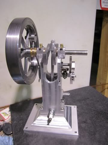
Topsy Turvy Hit & Miss Engine Build
- Thread starter Harold Lee
- Start date


Help Support Home Model Engine Machinist Forum:
This site may earn a commission from merchant affiliate
links, including eBay, Amazon, and others.
Harold Lee
Well-Known Member
- Joined
- Apr 23, 2008
- Messages
- 236
- Reaction score
- 2
Brock - Thank you very much for your encouraging words...
Rudy,
One of the problems with using the taper lock is making sure the two tapers are exactly the same angle. The MEB article spends a good bit of time explaining how to "dial in" the angle using a dial indicator and calculating angles. I'm sure it works well but it requires a bit of fiddling and there are some steps that could produce angular errors. The Steam & Stirling article it much simpler and practically foolproof. While both articles recommend a four degree angle, since one is internal and the other is external and normally requires the compound to be reset, The method used in the S&S article uses the same setting and conventionally bores the flywheel then the taper is turned on the back side with the lathe in reverse using the same compound setting. This is the method I have used and will document it on this build as well. The only downside is to make sure the chuck set screws are tight to prevent the chuck from unscrewing.
I'll post pictures of this method soon.
rudydubya said:<<<SNIP>>>
thanks for the reminder about that article in MEB issue #11, I had forgotten about it.
Regards,
Rudy
Rudy,
One of the problems with using the taper lock is making sure the two tapers are exactly the same angle. The MEB article spends a good bit of time explaining how to "dial in" the angle using a dial indicator and calculating angles. I'm sure it works well but it requires a bit of fiddling and there are some steps that could produce angular errors. The Steam & Stirling article it much simpler and practically foolproof. While both articles recommend a four degree angle, since one is internal and the other is external and normally requires the compound to be reset, The method used in the S&S article uses the same setting and conventionally bores the flywheel then the taper is turned on the back side with the lathe in reverse using the same compound setting. This is the method I have used and will document it on this build as well. The only downside is to make sure the chuck set screws are tight to prevent the chuck from unscrewing.
I'll post pictures of this method soon.
rudydubya
Well-Known Member
- Joined
- Nov 26, 2008
- Messages
- 337
- Reaction score
- 7
Harold Lee said:<<<SNIP>>>... The method used in the S&S article uses the same setting and conventionally bores the flywheel then the taper is turned on the back side with the lathe in reverse using the same compound setting. This is the method I have used and will document it on this build as well. The only downside is to make sure the chuck set screws are tight to prevent the chuck from unscrewing.
I'll post pictures of this method soon.
Thanks in advance, Harold. Looking forward to seeing how you do it.
Rudy
Harold Lee
Well-Known Member
- Joined
- Apr 23, 2008
- Messages
- 236
- Reaction score
- 2
Steve - Thank you... I started working on it last Friday but have other things to do so I am estimating I have 20 to 25 hours invested in it so far. I think I still have about 10 hours to go but since I am retired and use this to try to keep my mind active, I am not in a rush.
Lee - I am glad the step by step is beneficial. One of the reasons I decided to post my build was not because I considered myself an expert but I have learned so much from others posting their builds that I thought anything I can add would help. I find myself getting so wrapped up in the machining that I have to remind myself to stop, clean up the swarf, and take a picture before continuing.
Lee - I am glad the step by step is beneficial. One of the reasons I decided to post my build was not because I considered myself an expert but I have learned so much from others posting their builds that I thought anything I can add would help. I find myself getting so wrapped up in the machining that I have to remind myself to stop, clean up the swarf, and take a picture before continuing.
Harold Lee
Well-Known Member
- Joined
- Apr 23, 2008
- Messages
- 236
- Reaction score
- 2
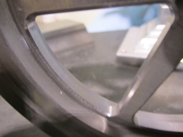
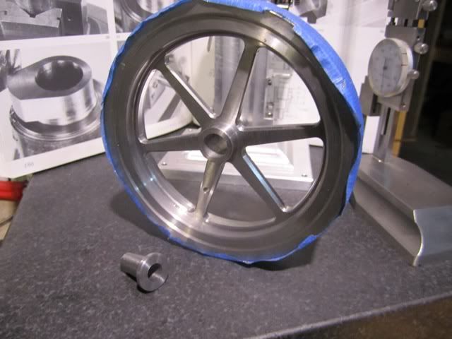
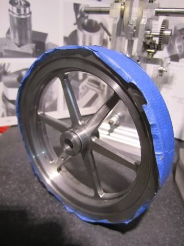
I cannot believe I spent the entire day on just chamfering the flywheel, but two sides X six spokes X both edges + six circumference pie shapes X two sides comes out to be a lot of chamfering.
I was very pleased with the results. All of the setup has made some "rash" on the flywheel edges and I am contemplating taking a clean up cut after I am done and before masking and painting.
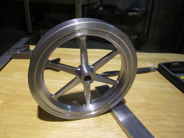
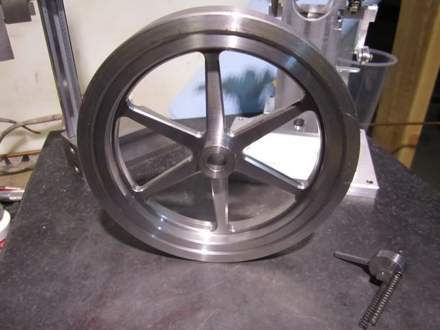
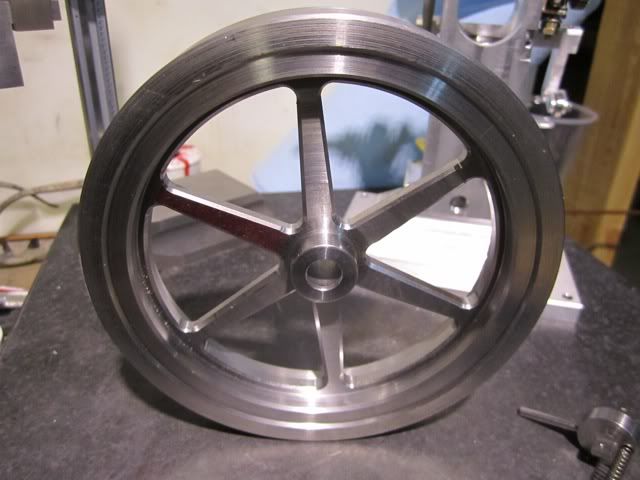
The next step is to make and fit the taper lock hub...
I was very pleased with the results. All of the setup has made some "rash" on the flywheel edges and I am contemplating taking a clean up cut after I am done and before masking and painting.
The next step is to make and fit the taper lock hub...
Harold Lee
Well-Known Member
- Joined
- Apr 23, 2008
- Messages
- 236
- Reaction score
- 2
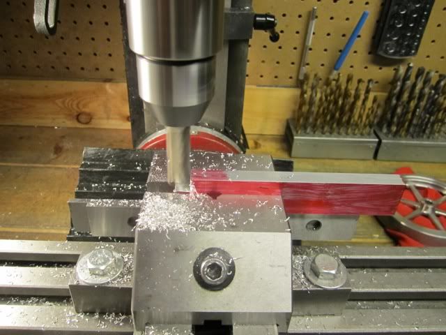
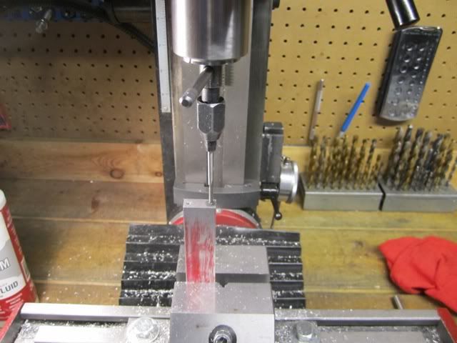
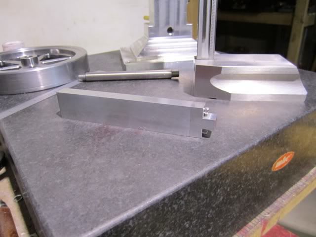
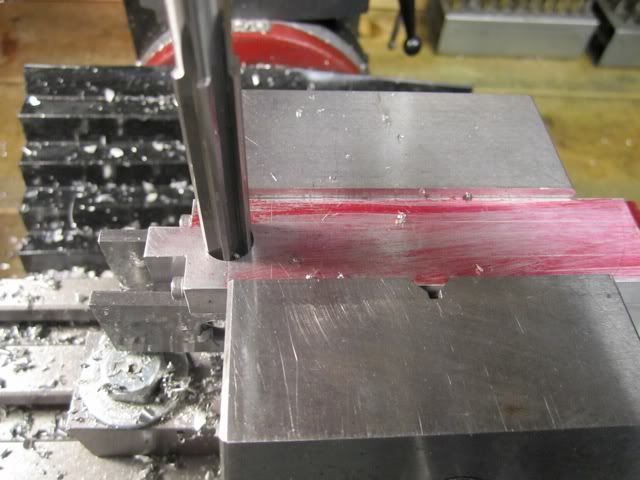
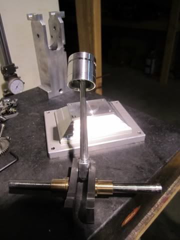
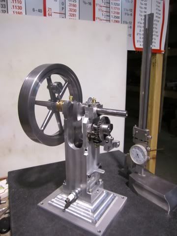
Despite the fact that in my last post I was going to make the taper lock for the flywheel, I decided to make the connecting rod instead. My logic is that when the connecting rod and piston are complete I can assemble the bottom end of the engine and move on. As it presently stands, I cannot mount the flywheel since the model will fall over due the top heavy nature of the design. With that in mind I dug some 6061 T6 out of my stock and started machining...
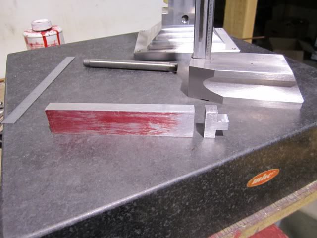
First was to get the stock to size on my shaper.
The next step is to rough mill the connecting rod end cap.
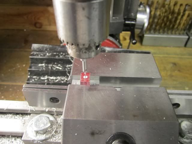
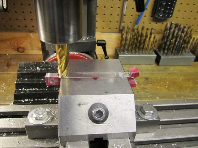
Locate and drill the bolt holes. These holes are drilled deep enough to also drill the holes in the rod which will be tapped after the cap is sawed off. Even though I have indicated the holes, at this point the orientation of the cap to the rod is determined and will be constant moving forward.
Notice in the above picture that after removing the cap and finishing off the end, I have about .090 to remove to bring the rod length to proper dimensions.
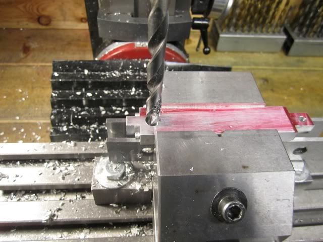
Tapping the holes... At a later time I will also drill out the rod caps for a close fit clearance for the bolts.
At this point the parts are secured and a witness punch mark is placed on each part.
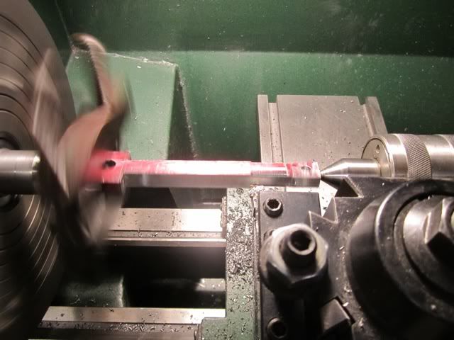
The two parts are center drilled for turning the rod on the lathe which will take place after the rod is milled to rough finished dimensions and the big end and small end are located, drilled and reamed.
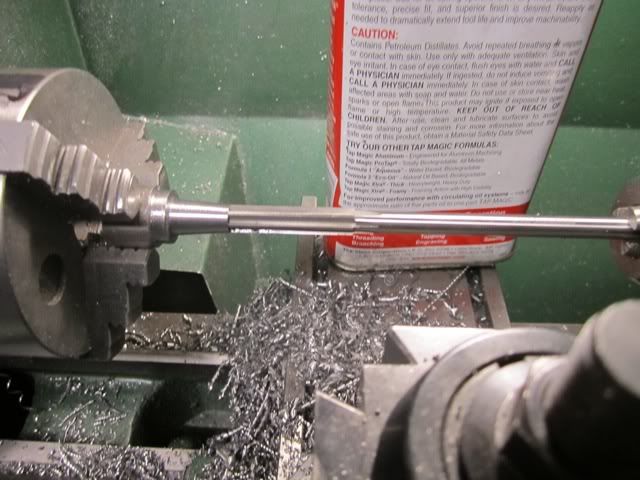
At this stage the rod is put on the lathe for turning. The rod is tapered and after getting it to dimensions, I am going to need to do a lot of hand filing. (where is that taper attachment when you need it?)
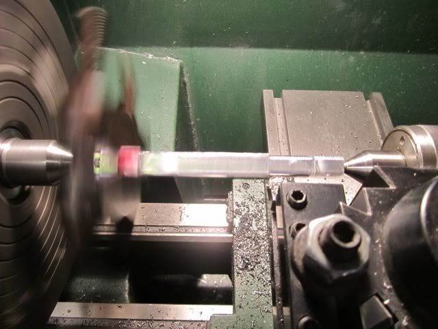
Ok... Took a few hours and many stops to measure and clean the file but finally it is done.
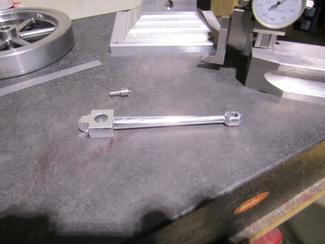
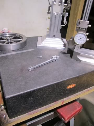
I think I'll make the piston next...
First was to get the stock to size on my shaper.
The next step is to rough mill the connecting rod end cap.
Locate and drill the bolt holes. These holes are drilled deep enough to also drill the holes in the rod which will be tapped after the cap is sawed off. Even though I have indicated the holes, at this point the orientation of the cap to the rod is determined and will be constant moving forward.
Notice in the above picture that after removing the cap and finishing off the end, I have about .090 to remove to bring the rod length to proper dimensions.
Tapping the holes... At a later time I will also drill out the rod caps for a close fit clearance for the bolts.
At this point the parts are secured and a witness punch mark is placed on each part.
The two parts are center drilled for turning the rod on the lathe which will take place after the rod is milled to rough finished dimensions and the big end and small end are located, drilled and reamed.
At this stage the rod is put on the lathe for turning. The rod is tapered and after getting it to dimensions, I am going to need to do a lot of hand filing. (where is that taper attachment when you need it?)
Ok... Took a few hours and many stops to measure and clean the file but finally it is done.
I think I'll make the piston next...
Harold,
As per usual very well photographed and machined. This is a super well done engine and will be even more so once it's completed.
You need a Morse taper, Taper turning attachment for the tailstock. These have a center that can be offset. They were and are built even today. Arrand in the U.K. make them, Unfortunatly AFAIK they only make the dead center types. Royal at one time made a real high end one with a live center. They do show up on Ebay once in awhile but always go for big bucks. I've been searching for one of those types that would take something like a hardened tooling ball and has proper bearings for a live center. Sooner or later I'm going to have to build one I guess.
Pete
Harold Lee
Well-Known Member
- Joined
- Apr 23, 2008
- Messages
- 236
- Reaction score
- 2
Thank you for your encouragement Pete... The Morse taper turning attachment sounds like a good solution. I have not seen one but can imagine what they look like in my mind. I'm guessing there is a Morse taper shank, some method of a positive registration in the horizontal plane and an adjustment like an adjustable boring bar... Wonder if a boring bar head could be adapted? Hmmmmm...
The next project was to complete the piston and fit the lower end together. The pictures I took of the piston turning were blurry so I'll pick it up with cutting the inter clearance for the rod end. The slot was drilled and bored to .375 on the lathe before parting off. I transferred the part to the mill and used a coaxial indicator to locate the exact center. Then using a 3/8 end mill I made the clearance slot.
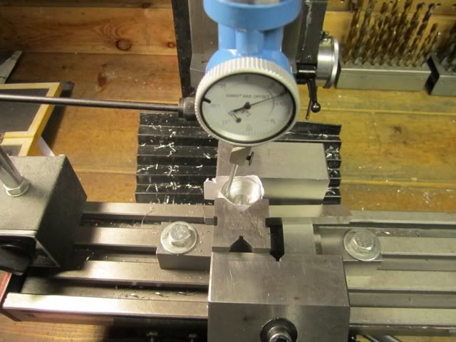
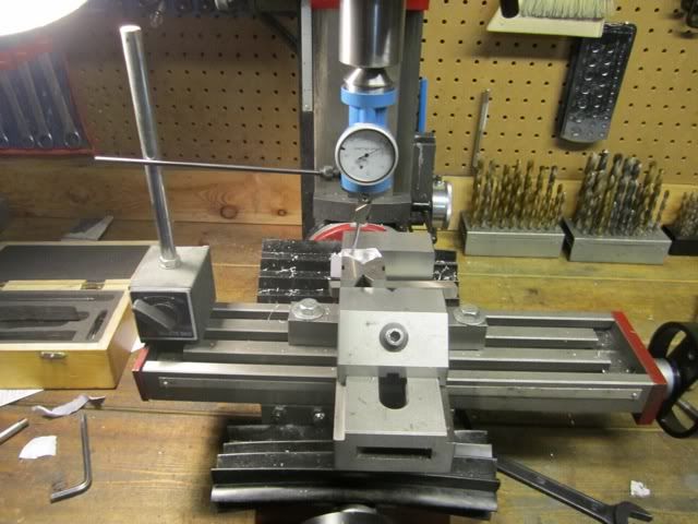
Since I wanted to ensure the wrist pin hole was exactly 90 degrees to the internal slot, after milling the slot using the Y axis, I then turned the vise on its side and then located and drilled, and reamed the wrist pin hole.
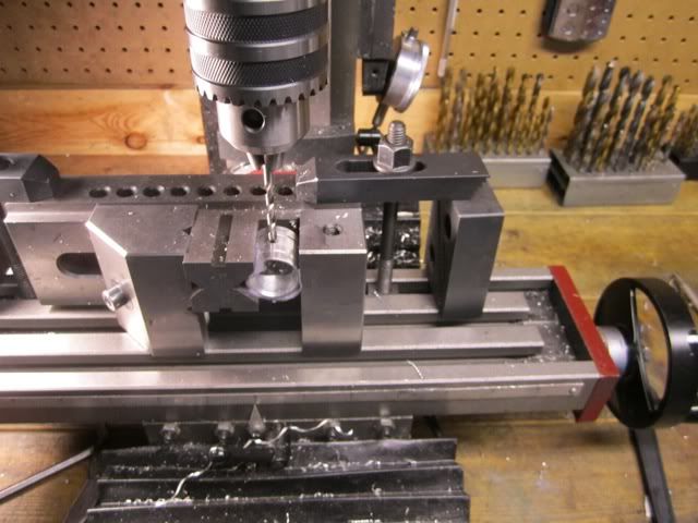
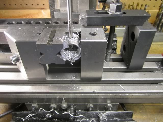
I was pretty pleased with the results. I have decided to use an O ring on this piston even though I have a set of rings, so I only made a single slot for it. The small v grove on the skirt of the piston is for trapping and distributing oil around the circumference of the cylinder.
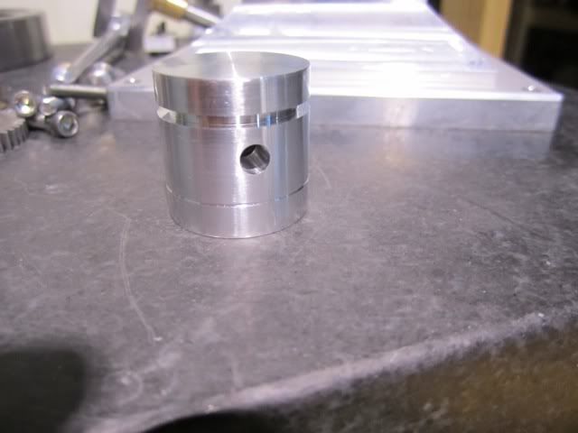
The tapered crankshaft interferes with the top edge of the cylinder liner and about .050 must be removed with a rile or burr for clearance. After that it all worked very smoothly.
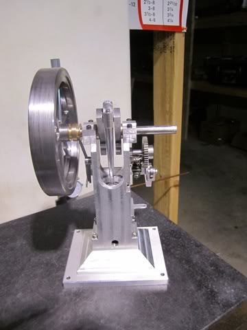
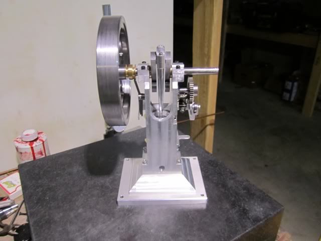
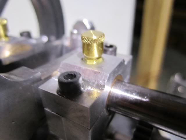
The next project was to install the main bushing lubrication. The original design called for oil holes drilled in the top of the rod caps and then located and drilled through the bronze bearings. I hope to reduce the amount of oil slinging and decided to put grease caps and use grease.
The next and last project of the day was to complete the governor pivot and calibrate the speed by cutting and adjusting the spring. I made a fixture for slotting the governor pivot. This allowed me to slot it using the Y axis of the mill and then move the fixture to the side of the vice and drill and tap the pivot pin hole. In this manner, the slot and pin would be exactly 90 degrees apart.
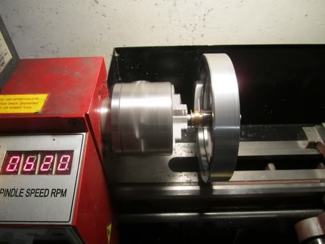
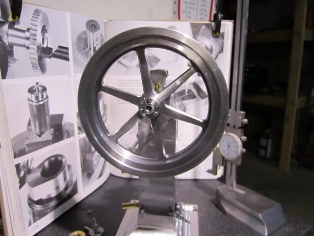
After installing the governor on the flywheel I put it on my lathe to check the RPM against the governor actuation. At 620 RPM the governor was completely retracted and at this point the engine would be firing to increase speed. At 740 RPM the governor was fully engaged and the engine would be coasting.
Since the pictures are difficult to see, I turned out the lights and forced the camera to flash. This strobe effect stopped the blur.
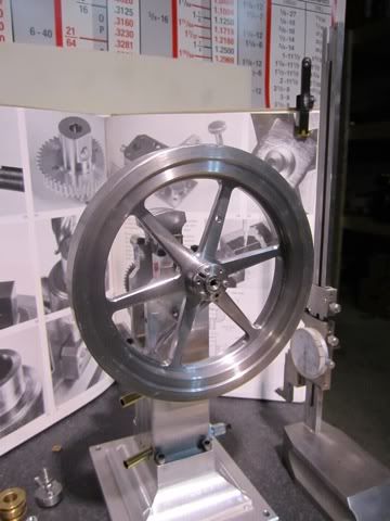
Notice on the above picture (620 RPM) the brass governor spool is against the flywheel hub. On the picture below (740 RPM) the spool has moved to the left.
I am sure some fine tuning will be required once the engine is running but at least this puts me in the ball park.
All in all, a pretty good day...
I think I'll make the valve bodies next...
The next project was to complete the piston and fit the lower end together. The pictures I took of the piston turning were blurry so I'll pick it up with cutting the inter clearance for the rod end. The slot was drilled and bored to .375 on the lathe before parting off. I transferred the part to the mill and used a coaxial indicator to locate the exact center. Then using a 3/8 end mill I made the clearance slot.
Since I wanted to ensure the wrist pin hole was exactly 90 degrees to the internal slot, after milling the slot using the Y axis, I then turned the vise on its side and then located and drilled, and reamed the wrist pin hole.
I was pretty pleased with the results. I have decided to use an O ring on this piston even though I have a set of rings, so I only made a single slot for it. The small v grove on the skirt of the piston is for trapping and distributing oil around the circumference of the cylinder.
The tapered crankshaft interferes with the top edge of the cylinder liner and about .050 must be removed with a rile or burr for clearance. After that it all worked very smoothly.
The next project was to install the main bushing lubrication. The original design called for oil holes drilled in the top of the rod caps and then located and drilled through the bronze bearings. I hope to reduce the amount of oil slinging and decided to put grease caps and use grease.
The next and last project of the day was to complete the governor pivot and calibrate the speed by cutting and adjusting the spring. I made a fixture for slotting the governor pivot. This allowed me to slot it using the Y axis of the mill and then move the fixture to the side of the vice and drill and tap the pivot pin hole. In this manner, the slot and pin would be exactly 90 degrees apart.
After installing the governor on the flywheel I put it on my lathe to check the RPM against the governor actuation. At 620 RPM the governor was completely retracted and at this point the engine would be firing to increase speed. At 740 RPM the governor was fully engaged and the engine would be coasting.
Since the pictures are difficult to see, I turned out the lights and forced the camera to flash. This strobe effect stopped the blur.
Notice on the above picture (620 RPM) the brass governor spool is against the flywheel hub. On the picture below (740 RPM) the spool has moved to the left.
I am sure some fine tuning will be required once the engine is running but at least this puts me in the ball park.
All in all, a pretty good day...
I think I'll make the valve bodies next...
Harold Lee
Well-Known Member
- Joined
- Apr 23, 2008
- Messages
- 236
- Reaction score
- 2
@gbritnell & Steve, Thank both of you for your encouraging comments. I do think that the fact that I must show my work helps me to try to do a better job while I am working. Regarding you question Steve about colors. I really like the rustoleum hammered paints since the finish more closely resembles castings. I was thinking about a black for the flywheel and trim and either the bronze or copper for the body.
http://www.rustoleum.com/CBGProduct.asp?pid=29
I am very open to suggestions or recommendations as I do not consider myself to be any expert on color schemes. Feel free to jump in if someone has a suggestion.
http://www.rustoleum.com/CBGProduct.asp?pid=29
I am very open to suggestions or recommendations as I do not consider myself to be any expert on color schemes. Feel free to jump in if someone has a suggestion.
Harold Lee
Well-Known Member
- Joined
- Apr 23, 2008
- Messages
- 236
- Reaction score
- 2
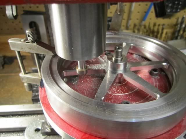
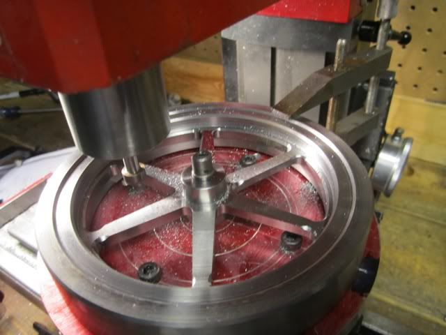
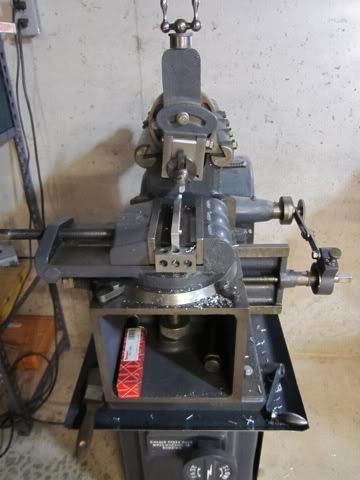
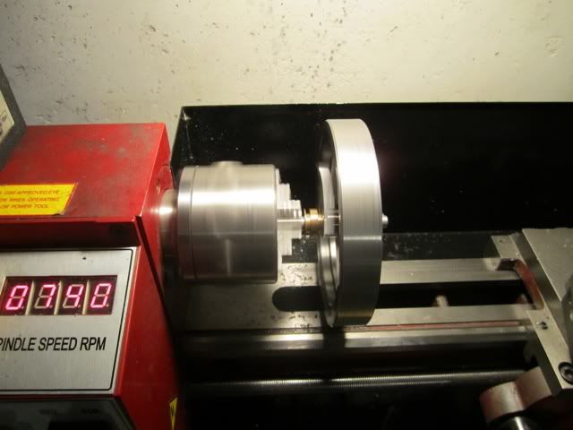
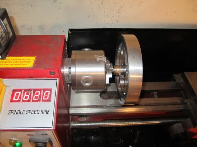
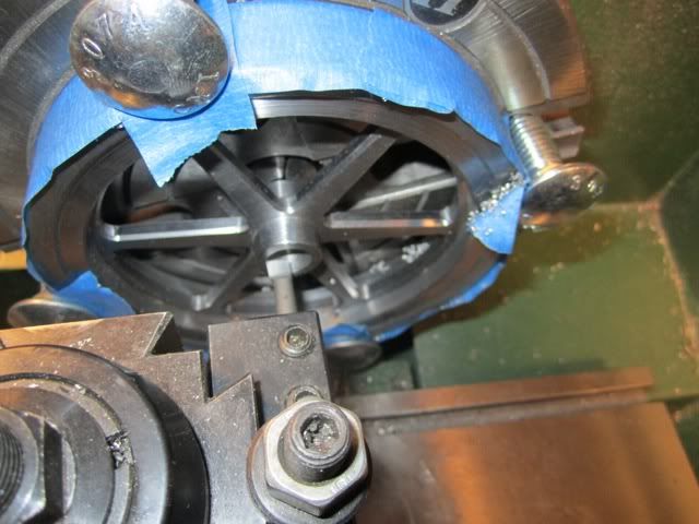
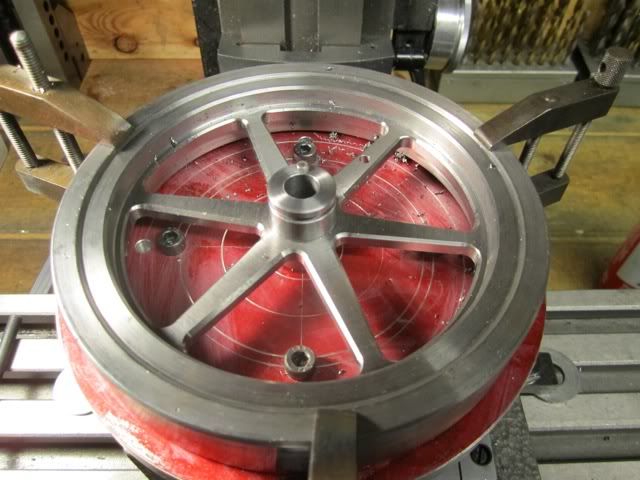
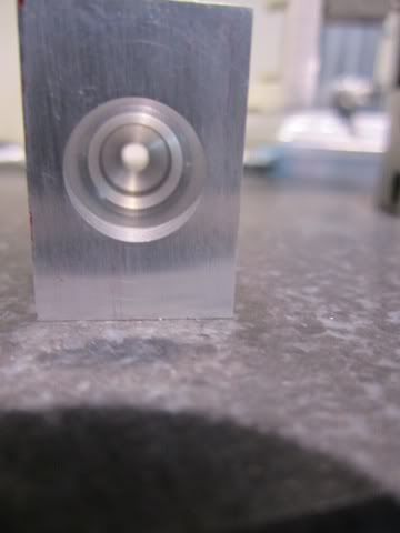
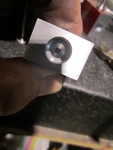
In my last progress post I mentioned that I was going to make the valve bodies next. This morning I cleaned up my surface plate and got my two block of metal which I had previously machined to size. I then took a look at the flywheel and realized that I had not made the taper collet for holding it on the crankshaft. Doh!!! I put my two blocks away and decided to make the taper bushing. The first thing was to mount the flywheel on the lathe and set up the cross slide for a 4 degree angle. I have found that the best way to center the flywheel on the lathe is to push a mandrel into the flywheel and a mt3 collet on the headstock. At this point I clamp the flywheel to the faceplate and remove the mandrel so I can bore the angle. I have a regular faceplate for my lathe but when I put the collet in the headstock there is about a 3/8 gap between the flywheel and the faceplate. The first time I did this on a previous flywheel I placed .375 tool bits between the plate and the flywheel and then considered what I had done. Here was a 6 pound mass turning at 400 RPM just waiting to sling those tool steel missiles off at anything in a 360 degree arc. Since that included my head and body I thought there must be a better way. Fortunately my 4 jaw chuck is of the "old school" design where it is really a thick, heave faceplate with precision ground ways for the jaw to seat in. Since it is thicker, the flywheel will mount directly to it without any shimming.
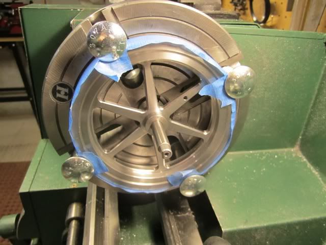
BTW - I looked ant these pictures and it is not obvious but the tape in only on the edge and front face. The flywheel is directly against the faceplate surface.
Carriage bolts and large washers on the back make perfect clamps...
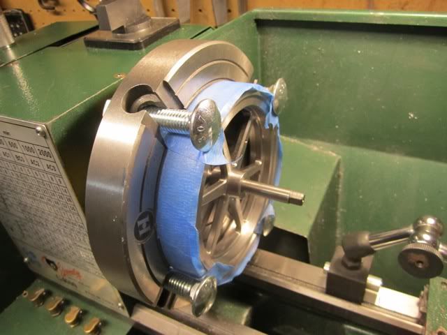
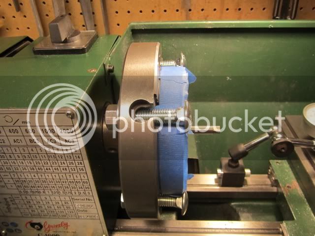
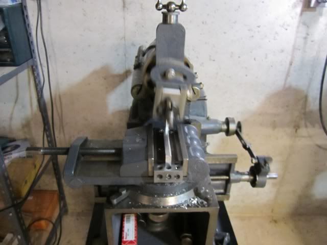
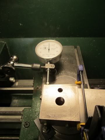
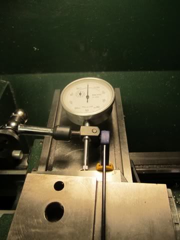
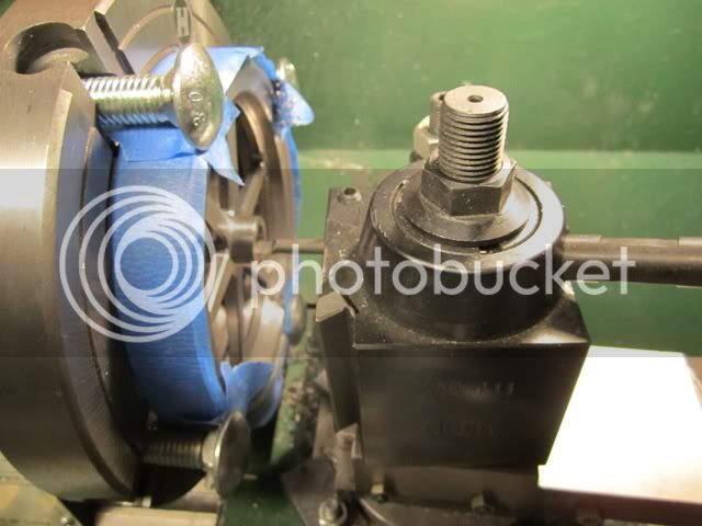
The next step is to set the compound slide to 4 degrees. I have made a "beefed up" tool post and did not put any angle markings on it so I took a 4 degree angle and clamper to the compound and with an indicator on the lathe ways set it compound for equal readings. I made the assumption that the edge of the compound was parallel to the compound travel.
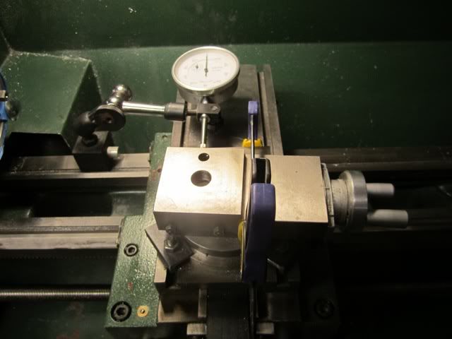
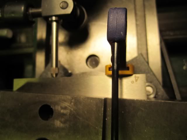
Here are pictures of both ends of travel....
I took .010 cuts until the OD of the taper at the edge was .510
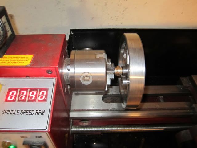
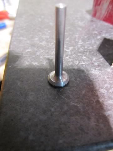
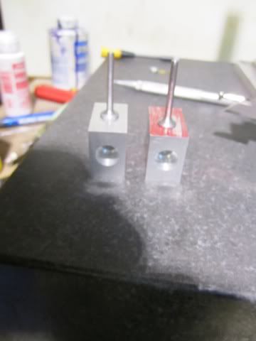
At this point the flywheel was done. The next step was to turn the taper collet.
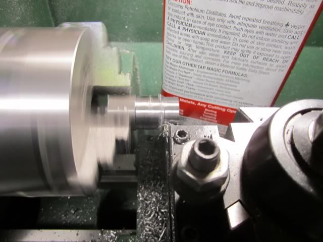
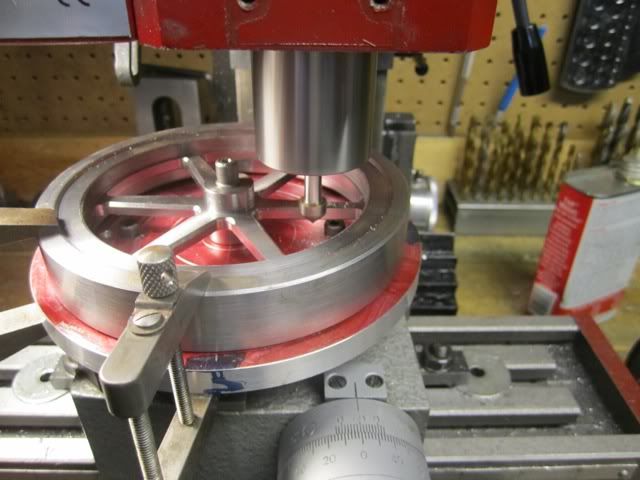
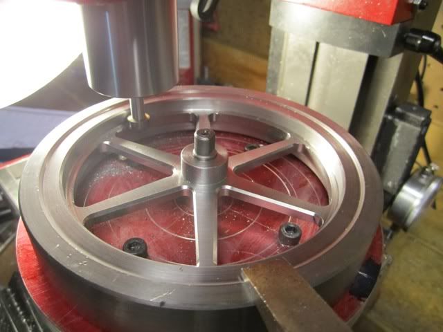
After roughing the adapter to size and AFTER tightening the two set screws on the chuck that prevent it from unscrewing ( EXTREMELY IMPORTANT STEP!!! ). I ran the lathe backwards and machined the taper from the rear.
The advantage of this method is that both the flywheel and the collet are machined to exactly the same angle since the set up is not moved from one operation to the other.
After a few trial fittings an getting the clearance I wanted I then drilled and reamed the shaft hole, and parted it off.
I then moved it to the mill and rotary table where I first drilled and tapped the first hole to hold the registration between the two parts and then made all of the holes and tapped them.
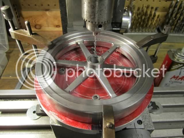
The last milling operation was to mill out the face of the collet for slitting it. I milled the face and then used a jewelers saw to cut the tapered part.
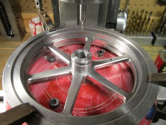
Now I can start work on the valve bodies...
BTW - I looked ant these pictures and it is not obvious but the tape in only on the edge and front face. The flywheel is directly against the faceplate surface.
Carriage bolts and large washers on the back make perfect clamps...
The next step is to set the compound slide to 4 degrees. I have made a "beefed up" tool post and did not put any angle markings on it so I took a 4 degree angle and clamper to the compound and with an indicator on the lathe ways set it compound for equal readings. I made the assumption that the edge of the compound was parallel to the compound travel.
Here are pictures of both ends of travel....
I took .010 cuts until the OD of the taper at the edge was .510
At this point the flywheel was done. The next step was to turn the taper collet.
After roughing the adapter to size and AFTER tightening the two set screws on the chuck that prevent it from unscrewing ( EXTREMELY IMPORTANT STEP!!! ). I ran the lathe backwards and machined the taper from the rear.
The advantage of this method is that both the flywheel and the collet are machined to exactly the same angle since the set up is not moved from one operation to the other.
After a few trial fittings an getting the clearance I wanted I then drilled and reamed the shaft hole, and parted it off.
I then moved it to the mill and rotary table where I first drilled and tapped the first hole to hold the registration between the two parts and then made all of the holes and tapped them.
The last milling operation was to mill out the face of the collet for slitting it. I milled the face and then used a jewelers saw to cut the tapered part.
Now I can start work on the valve bodies...
rudydubya
Well-Known Member
- Joined
- Nov 26, 2008
- Messages
- 337
- Reaction score
- 7
Nice presentation on doing the split collets Harold. Thanks. On the final size of the holes in the collet for the screws into the flywheel, is a normal free-fit-sized hole sufficient, or do you have to allow a bit more for any contraction of the collet diameter as it's pulled into the flywheel?
Rudy
Rudy
Harold Lee
Well-Known Member
- Joined
- Apr 23, 2008
- Messages
- 236
- Reaction score
- 2
Rudy - Since the collet is reamed to the shaft size and fitted to the flywheel, there is only a few thousandths of shrinkage as the collar pulls up. I drill for a close fit clearance which in this case of a 2-56 screw is a #43 which is .089. This is the seventh flywheel I have done this way and have never had any problems with binding.
Harold Lee
Well-Known Member
- Joined
- Apr 23, 2008
- Messages
- 236
- Reaction score
- 2
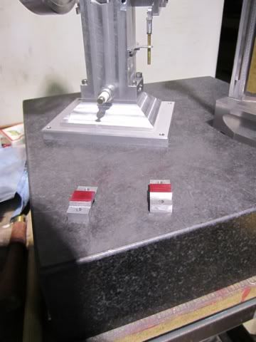
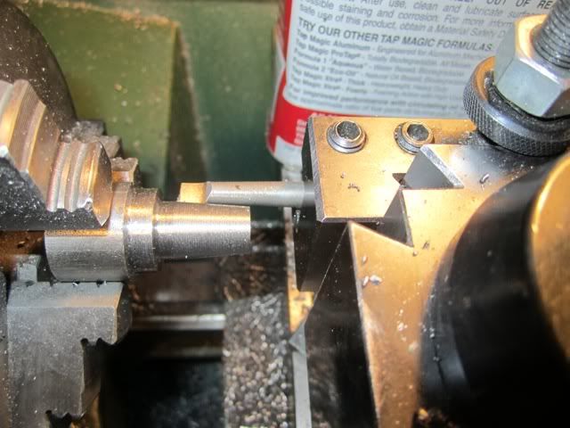
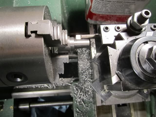
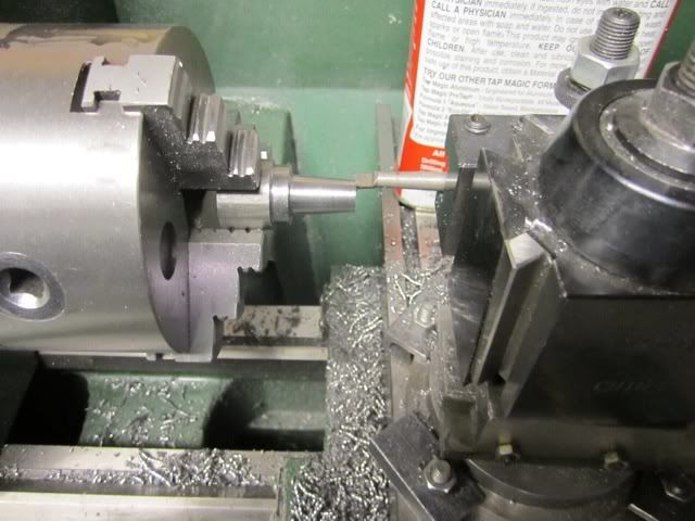
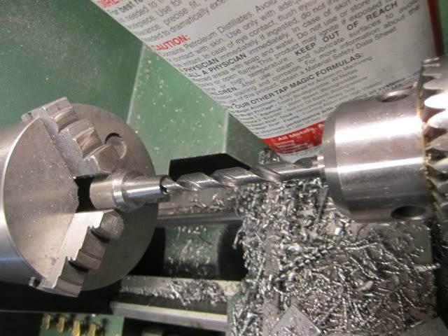
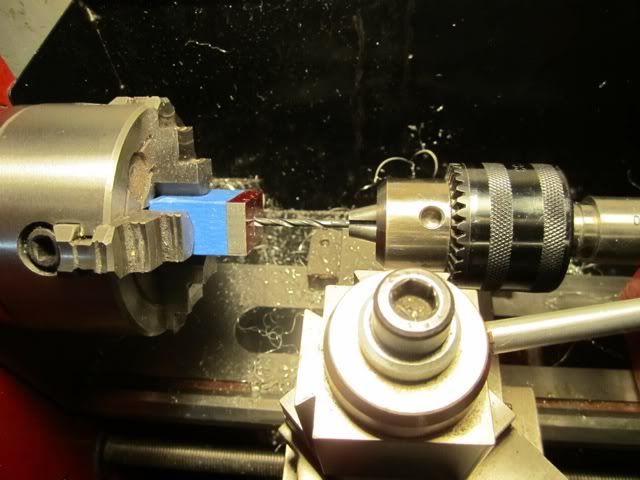
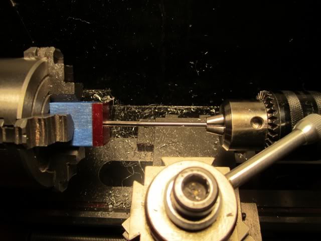
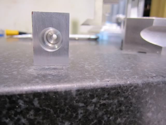
Today I made the bored the two valve bodies, made the valves and lapped them in. I centered the body in my 4 jaw on my small lathe and used an indicator to center it.
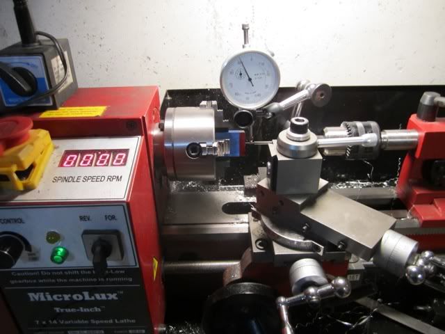
From there it was drill and ream the valve stem hole through the part and then drill the clearance, bore the body and cut the valve seat on a 45 degree angle.
Next the two valves were turned and lapped. The picture doesn't show as well as I would have hoped but the lapped seat is "frosted" on both parts. My past experience has shown that if this happens, the valve will seat well and not leak.
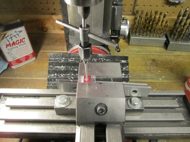
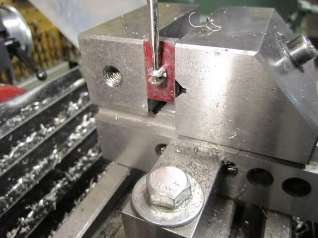
The print calls for a #60 drill 1/16 from the end to insert a music wire pin to hold the keeper and spring on. Trying to drill a hole in the center of a .125 shaft is like trying to nail jelly to a tree so I made a fixture which I have used more times than I care to count but it does the job and I keep my composure.
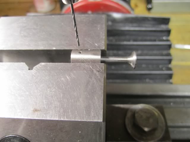
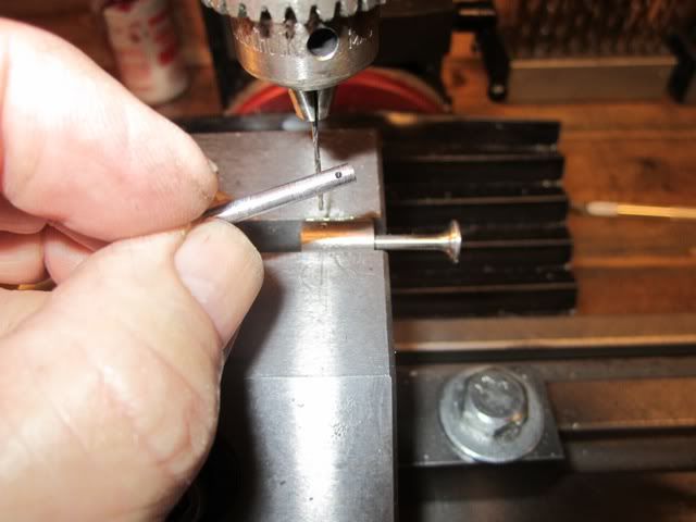
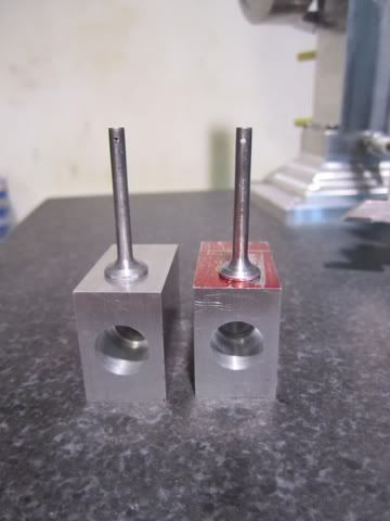
The next will be to machine the valve bodies to size and make the end covers.....
From there it was drill and ream the valve stem hole through the part and then drill the clearance, bore the body and cut the valve seat on a 45 degree angle.
Next the two valves were turned and lapped. The picture doesn't show as well as I would have hoped but the lapped seat is "frosted" on both parts. My past experience has shown that if this happens, the valve will seat well and not leak.
The print calls for a #60 drill 1/16 from the end to insert a music wire pin to hold the keeper and spring on. Trying to drill a hole in the center of a .125 shaft is like trying to nail jelly to a tree so I made a fixture which I have used more times than I care to count but it does the job and I keep my composure.
The next will be to machine the valve bodies to size and make the end covers.....
rudydubya
Well-Known Member
- Joined
- Nov 26, 2008
- Messages
- 337
- Reaction score
- 7
Harold Lee said:Rudy - Since the collet is reamed to the shaft size and fitted to the flywheel, there is only a few thousandths of shrinkage as the collar pulls up. I drill for a close fit clearance which in this case of a 2-56 screw is a #43 which is .089. This is the seventh flywheel I have done this way and have never had any problems with binding.
Thanks Harold. Probably obvious to everybody except me. When the collet is tight on the shaft, the collet will not be pulled into the flywheel, the flywheel will be pulled onto the collet...
Rudy
Groomengineering
Well-Known Member
- Joined
- Aug 2, 2009
- Messages
- 242
- Reaction score
- 3
rudydubya said:Thanks Harold. Probably obvious to everybody except me. When the collet is tight on the shaft, the collet will not be pulled into the flywheel, the flywheel will be pulled onto the collet...
Rudy
Yes, but once the collet is tight on the shaft you're done. No need to keep tightening. Thm:
Harold, very nice work so far! Can't wait to see it running! :bow: :bow:
Cheers
Jeff
Similar threads
- Replies
- 0
- Views
- 766
- Replies
- 148
- Views
- 22K
- Replies
- 5
- Views
- 2K