ET Westbury Side Paddle Engine

Home Model Engine Machinist Forum

Help Support Home Model Engine Machinist Forum:

This site may earn a commission from merchant affiliate links, including eBay, Amazon, and others.
Made another pair of feet this evening. Still surprising how much time these simple parts take.

large.jpg
 
Some small progress on the engine the past few days.

Made the front feet for the inner frames; no pics for these, but similar to the others.

The next goal is to make the bearings for the crankshaft. I decided to make these as 1 piece and fit the crank to them before mounting to the frames. This is possible as there are separate crankshafts for each cylinder. These will be milled from some 1" round brass bar. I tried the first via CNC milling yielding a .6"x.8"x1" blank. Afterwards I thought up a better/quicker way that I'll document in a later post. The first step is facing the end of the bar on the lathe via a 1" collet, then mounting the bar and collet in a square collet block.

large.jpg


The CNC mill then carves out a .8x.6 profile 1" deep.

large.jpg


I then "whittled" out slots on the side and bottom to fit one of the frame hornblocks using the Bridgeport. I screwed up and made the side slots too wide, so this will be scrapped. Once the block will slide fully onto the hornblock, I measure the amound the top extends beyond the hornblock and then mill it flat.

large.jpg


The bearings are held in place by a strap across the top of the hornblock. It's necessary to drill and tap two holes for the screwing the strap to the hornblock. Here's the setup in the milling vise:

large.jpg


I managed to get a second bearing block fitted before leaving the shop, as well as drilling and tapping all 4 hornblocks.

large.jpg


Next time out I'll try to fit three more bearing blocks and make the retaining straps. Then it's back to the CNC to bore and ream the holes for the crankshafts.

 
Very nice kvom.
I need to learn more about this. Caused me to do some searching and found some interesting stuff.

Newbie question...can this engine be used for either a side paddle or stern paddle?
 
Zee---Some guesswork here on my part, but to steer a side wheeler they would have to have independent speed control and reverseability for the two side wheels---thus two seperate crankshafts as has been mentioned. Is this engine actually two reverseable engines side by side on a common frame?---Likewise, to steer a stern wheeler, the stern wheel would have to be split on the center long axis of the boat with each half being independent of the other to allow steerability without a rudder. If that is so, then the engine would probably work for a stern wheeler with chain drive from each independent crankshaft to each independent half of the split stern wheel.---Its an interesting concept. When I was about 12 or 13 years old, I rigged up a bicycle frame in a flat bottomed boat, with a chain drive to a peice of 3/4" waterpipe which rested on top of the boatsides, with a paddlewheel made out of wood on each end. It worked great, but I had to mount a rudder on the rear of the boat to steer it with, as the paddlewheels were not independent of each other. The next year, I converted it to a sternwheeler, driven by an old gasoline washing machine engine. My gear reduction was via a couple of 3" diameter v-belt pulleys driving 26" bicycle wheels with the tires removed, to act as giant v-pulleys. I remember that it was a total pig to steer, the v-belts slipped really bad when they got wet, and if I gave it too much gas, the revolving stern wheel would lift up water and thow it into the back of the boat, rapidly filling the boat with water. My thoughts at the time were to convert back to side wheels with a couple of jack-shafts with independent belt tensioners to allow me to steer via slip clutches. Unfortunately, entering high school and discovering GIRLS sidetracked my project, and the final change was never made.---I can still remember a lot of wonderful sun filled summers, paddleing around the lake and trolling for small mouth bass.-Brian
 
I believe in normal operation side paddlewheels were steered with a rudder and the wheels being locked together. While this engine is called a "set of engines', neither is self-starting if disconnected. This model has a separate junction piece to connect the two crankshafts.

This engine would is different than a stern paddle engine. Here the engines are canted upward to allow the engine mechanism to be down in the hull but the drive shafts elevated to the level of the deck.
\
A stern wheeler would typically have a much longer crank rod. The boats are shallow draft for rivers and hence the engines would be higher and oriented horizontally.
 
Kvom,

In the UK there were a group of ships called the 'Director' class. Not steam powered, but diesel/electric and did have independent paddle control, for maneuverability.

Royal Navy Paddle Tugs

Seven paddle tugs built for the Royal Navy, with the main role of providing berthing assistance to aircraft carriers. The very wide beam over the paddles allowed the tugs to tuck under the protruding flightdecks of carriers without catching their funnels. Dexterous, Director, Faithful and Forceful were built by Yarrow Shipbuilders at Scotstoun in 1957. Griper and Grinder were built by William Simons & Co at Renfrew in 1958. Favourite was built by Ferguson Brothers of Port Glasgow and launched on 1st July 1958. She was scrapped in 1980.
LOA 157', breadth 60', draught 10', 473 grt.
Engines: Four 12YHAXZ per vessel, each with a 24 hour rating of 585 bhp at 1,000 rpm. The engines for Favourite were ordered in January 1956 and despatched in December 1957.
Electrical Machinery: Each engine coupled to a 340kW generator. Two 600 volt DC propulsion motors per vessel, each producing 800 bhp at 212 rpm. The electrical machinery and control gear were manufactured by British Thomson-Houston.

http://rfaaplymouth.org/gallery2/main.php?g2_itemId=1519


Just another bit of useless information


John
 
Kvom,

I've just come across this, don't often check for new stuff as there is so much now it's hard to keep up with! You are making this look so easy now, those cylinders were a master class. I've not made any slide valve cylinders yet, it's still setting up for drilling the ports that worries me!

Well done :bow:

Nick
 
There is, (was in 1994), an English steam paddle tug at the San Francisco Maritime Museum. She had two scotch boilers and a separate engine driving each paddle. During my visit she was non operational but floating. At the time they did have an operating steam tug Hercules, Triple expansion with a nice size, oil fired scotch boiler.

Some of the locals could maybe photograph etc. if there is any interest.

Best Regards
Bob
 
A bit of progress today. I finished sizing the remaining three bearing blocks to their respective hornblocks, and made one of the retaining straps.

large.jpg


The center of the straps need to be drilled for an oil cup, but until I know how I'll make those I just center drilled a spot for a marker.

To make the rough bearing blocks from 1" round bar, here's the setup I used:

large.jpg


Before milling and boring the bearings, I need to do an assembly of the frames on each side to see how much room is there initially to fit the crank and conrod, and adjust accordingly. I start out with the length of the outer staybar, and from that subtract the thickness of the hornblocks and the amount the bearings extend. The distance from the inner frame to the center of the crank needs to be pretty close in order for the drive components (piston/rod/crosshead/conrod) to line up. It's not clear how close the tolerances need to be.

With that 1.25" endmill I could easily take .100" DOC, so it took only 6 passes to get the oblong. Then it was off to the bandsaw to cut it off. A smaller mill could still use this approach with smaller endmills and cuts.

I also spent some time tapping the base mounting holes on one of the cylinders. I found that the cast iron tapped quite easily with light finger pressure on the tapping stand, which was a relief.
 
Tis me again,thought you were going to CNC the tapped holes in the cyl ;D.Are you going to split the main bearings?
Don
 
I haven't dropped in for a while - am really enjoying the work you're showing. Thanks for keeping us posted.

Cheers,
Phil
 
Thanks to everyone that is following along.

Don, my CNC mill doesn't do rigid tapping, so all tapping including the cylinders is by hand. I'm not planning to split the bearings unless someone has a compelling reason to do so.

I did finish tapping both cylinders and tried fitting the end caps and glands. One end cap went on perfectly, but Unfortunately some of the holes are off by a "smidge" on the other. I'm not sure if it's because the bolt circle is not centered. For the end caps I can just file a bit on the holes with no problem. For the glands, the front bore and the inside spigot need to be aligned, so until I drill I won't know if I screwed up somewhere.
 
Got in 6 hours or so in the shop doing "little stuff", so not much to show photographically. Also found one big "boo-boo". Might be fixable.

The first job was to drill the cover mounting holes on one side of both cylinders. The other side was done via CNC when milling the profile. For this side I just centered the bore under the Bridgeport quill and used the DRO to locate the holes. Still took a long time to be sure of everything. After tapping all the remaining cylinder holes, I got the rear covers and one front cover to fit after some filing. Any opinions on using those 5-40 set screws as studs? Seems to look OK.

large.jpg


Notice anything wrong? The front cover needs to go on at a 90-degree angle from what's shown, meaning I'm missing one mounting hole and have an extra. I think I can put a dummy bolt in the extra hole and use the part.

In any case I drilled and tapped the holes in the front cover for mounting the crosshead guides. There was no dimension for locating the holes; I did a finger assembly and discovered that the end of the guides bars need to be flush to the front of the cover, so 5/32" out. With two bars attached, one crosshead slides very smoothly, but the other is a fraction tight at the near end.

medium.jpg


As regards the Grub screws in the Cyl cover,it is purly cosmetic but not steam engine practice,Studs or hex hd set screws look better but only a matter of choice.
I have a vid of our engine running ,may be of interest.

Don
 
Thanks for the video, Don. I hope mine ends up half as nice.

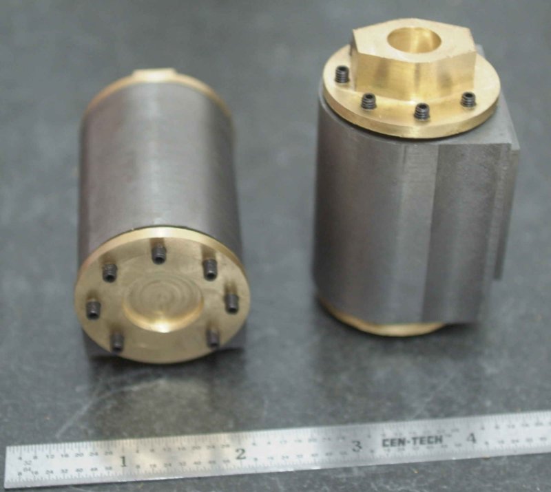
My "plan" is to use the grub screws as short studs but reverse them so that the hex hole in the end is not seen. By using two nuts as locks I can tighten them into the cylinder and other short blind 5-40 holes. I have ordered some hex-hex bolts from American Model Engineering that will be used to connect the cylinder to steam chest to cover. I also have some 5-40 threaded rod to use in other places as needed. Those model-scale nuts and bolts cost $0.30 each, so the model will have a lot of expense just in nuts and bolts.

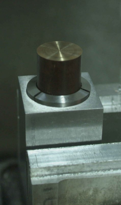
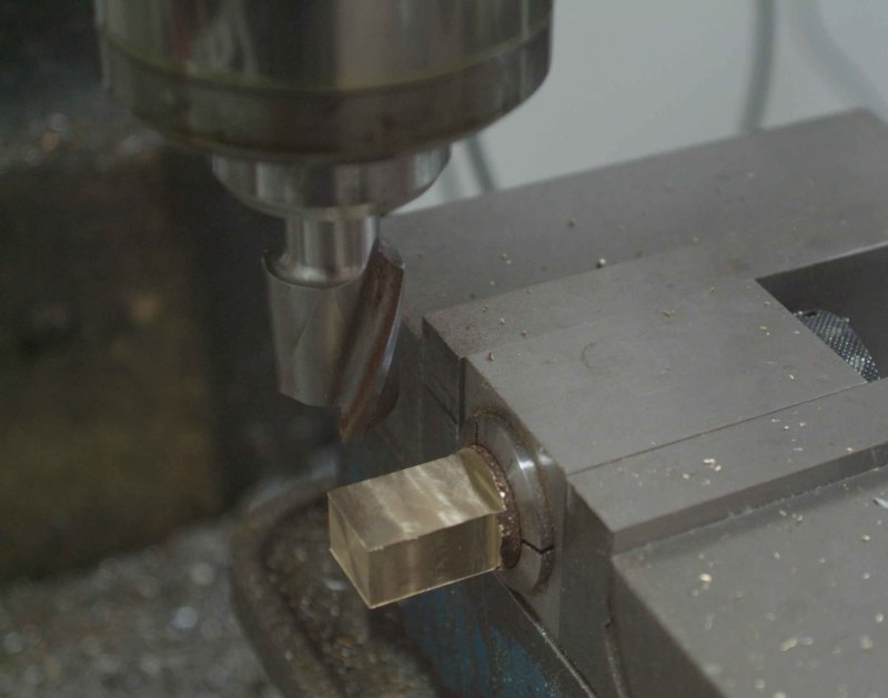
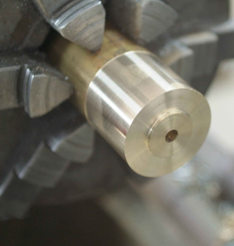
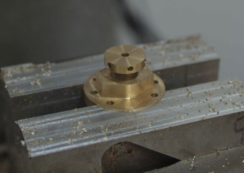
This weekend I bit the bullet and redid the inner cylinder covers to orient the mounting holes correctly. I also decided I could use the CNC mill to get accurate centering of the holes for the piston rod. The first order of business was a skim cut on some 1.5" diameter brass rod, yielding a diameter of 1.491". Without removing the rod, face, then turn the inner spigot of the cover to a close fit with the cylinder bore. Then drill a pilot hole and part off. Repeat for the second piece.

large.jpg


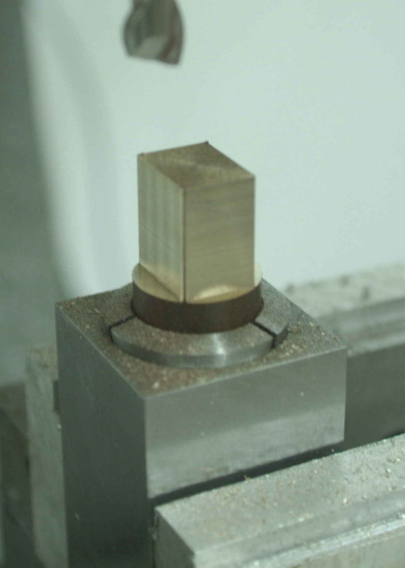
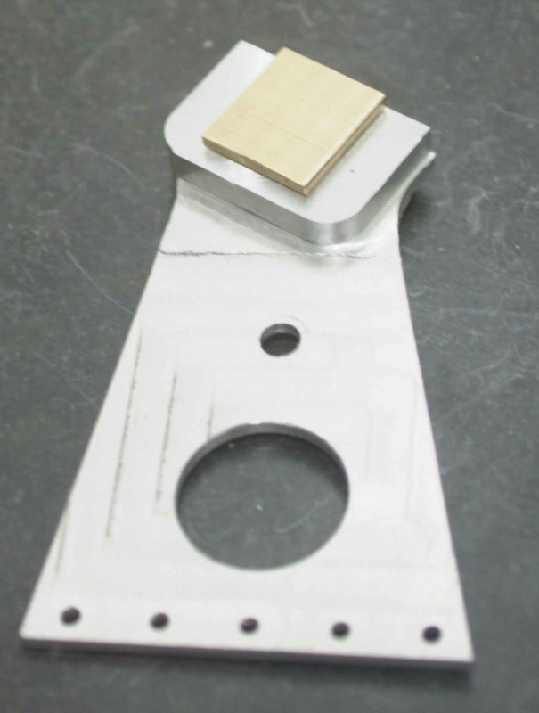
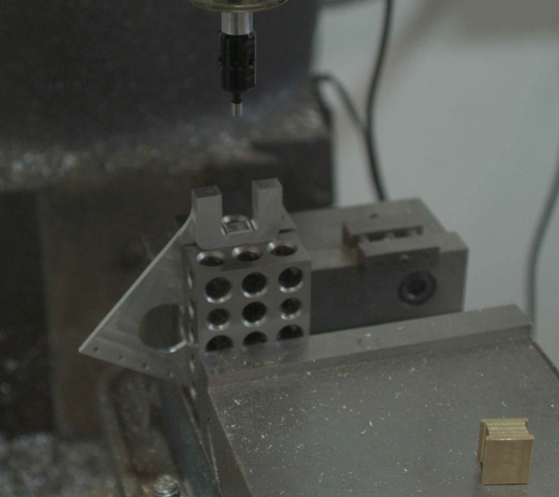
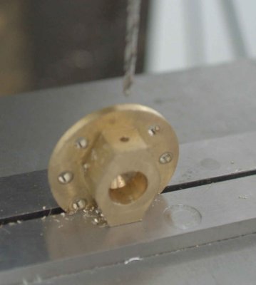
Next use the CNC mill to create a soft jaw pocket to match the diameter. Afterwards the Z-axis of the mill is centered on the pocket and thus the workpiece that's mounted in it. Now I can face the parted end, mill the profile, drill the mounting holes and the hole for the gland screw, and tap the hole for the screw using the 1/2-28 forming tap. Then screw in the gland screw and drill through it. Hopefully everything ends up concentric. I didn't have my .251" reamer handy, so that will be done later.

large.jpg


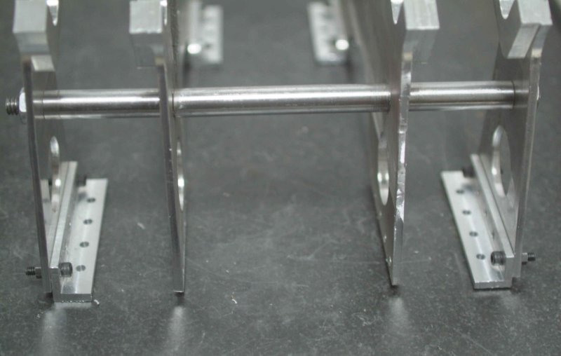
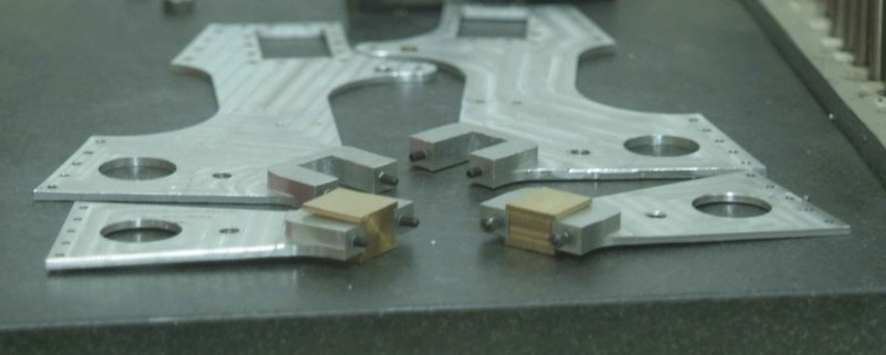
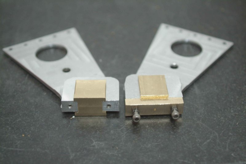
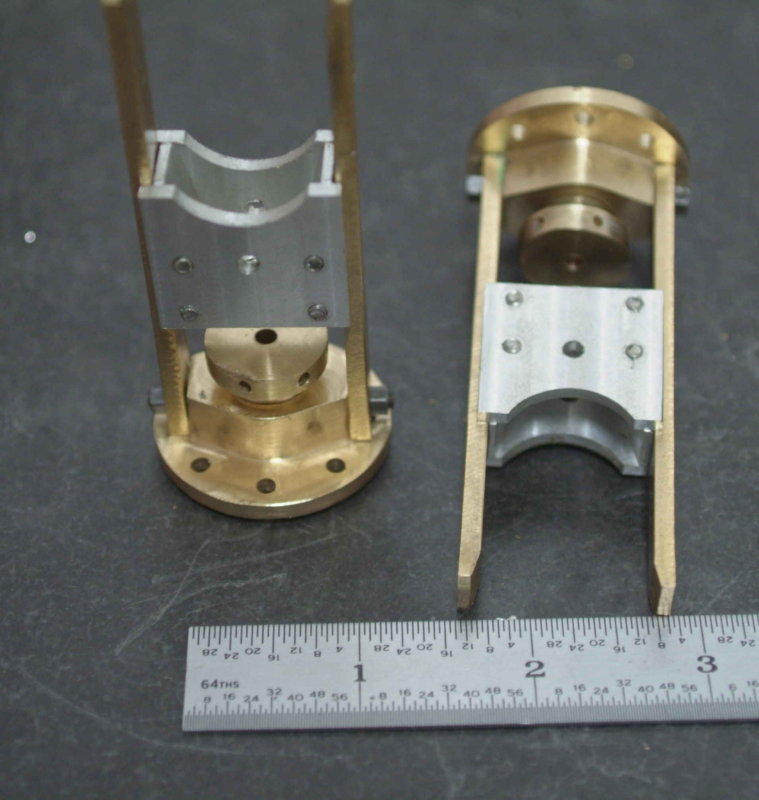
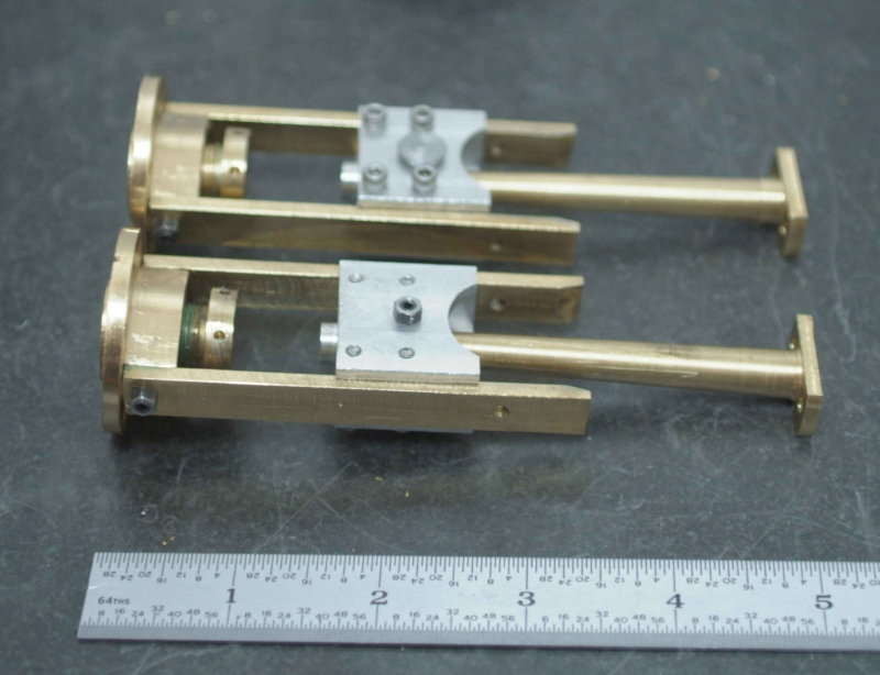
The last operation is manually drilling and tapping the holes for the crosshead guides, as shown in an earlier post. With everything assembled for a trial fit:

large.jpg


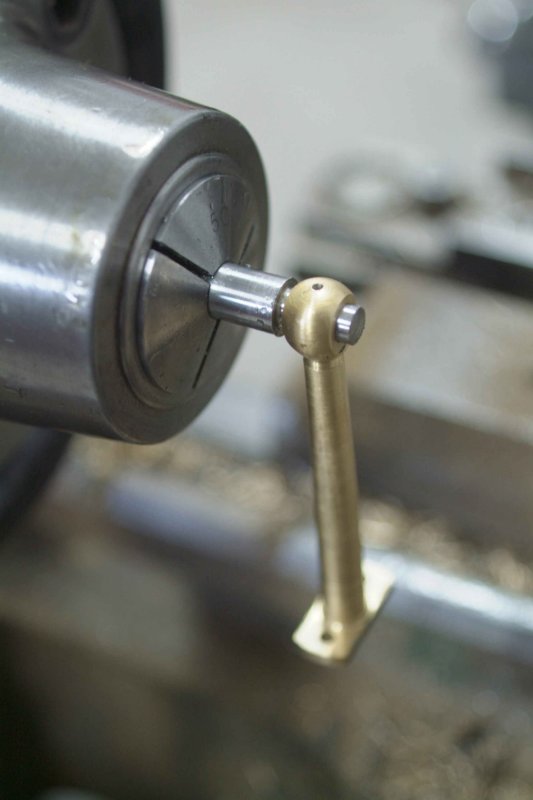
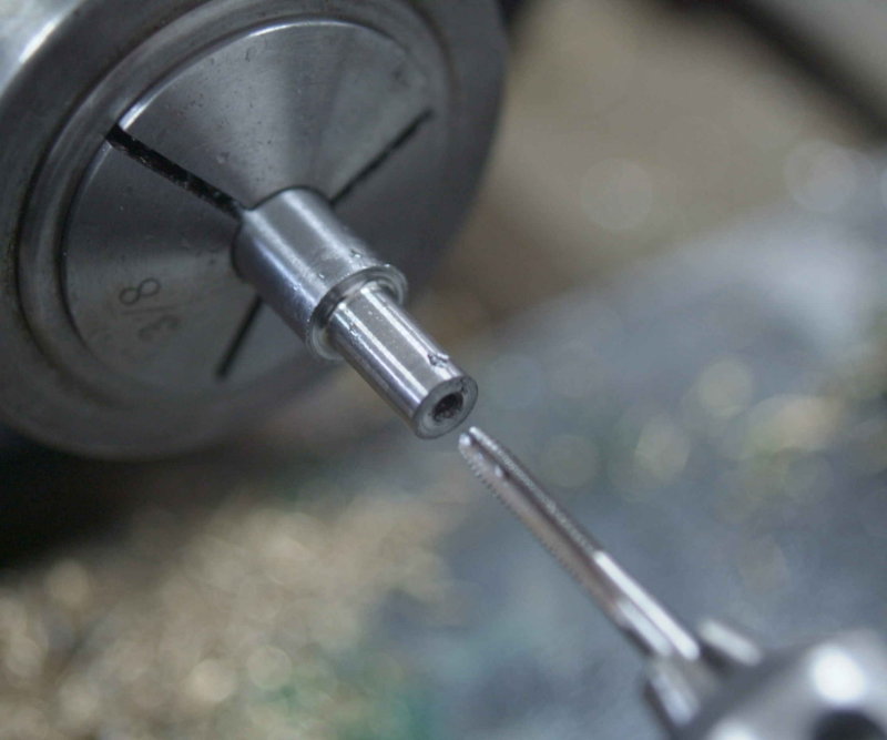
Of course, everything didn't go as smoothly as the above sequence would suggest. Biggest issue was that the gland scews would not go into cover more than 1/2 turn. The screws do go into the aluminum nut I made with the same tap, and the tap turns easily in the covers' threads. I tried to set up the lathe to potentially recut the threads a smidge deeper, but couldn't get the screws perfectly straight in the collet chuck. I finally decided to run a small triangular file into the threads while the lathe was turning slowly, and in addition put a slight bevel on the ends. Now I can get about 2 turns of the screw, so I'll just have to put enough packing into the glands.

My list of parts to finish is getting smaller:

Mill and bore crank bearings
One piston rod and piston
Crankshafts and the connector
Conrod pins
Lifting links
Remake one weigh link, plus some lever mechanism to move the weigh shaft
Eccentric discs
Remake one staybar
Some sort of base
Air plumbing to steam chest inlets

Got an order into Enco for materials plus some roll pins.

Then lots of filing, adjusting, cussing, and remaking anything that proved inadequate. One month to go before my 2-month trip, so mitmwill be close.

 
You can't go going away again,I will have nobody to have a go at.I hope you will finish this project. ;D.It's always a buggar getting all those bits to line up,I allways end up fiddling this or that to get a nice fit.
Glad you liked the vid,all without the aid of a flywheel,will you be making the paddle wheels?,if you need the drawings,I have a set if you do,now that's a cnc job.
Don
 
I don't plan to make the paddle wheels at this time. I noticed for the first time that you made the center eccentric for driving the feed pump. I hadn't planned on making that myself. At the time your engine was built, did you plan on steaming it?
 
Hi Kvom,We Made the eccentric to couple the two shafts together,it has the pump and piping but with no plans to steam her.
Don
 
Today's mini-project was making the conrod pins that connect the rod end to the crosshead. I chucked some 3/8" drill rod in the collet chuck, faced it, and turned to 1.4" diameter for a length of 1/2". The conrod ends have been reamed to .251, so I took off a couple of thou at a time until I had a nice sliding fit on the rod end:

large.jpg


Next, center drilled, drilled and tapped the end 5-40 for to depth of 3/8".

large.jpg


Next parted off leaving a "head" 1/16" thick. After making two, I reversed the pins in a 1/4" collet to smooth off the partoff tit.

Not having done so previously, I needed to drill and ream the center hole in the outside crosshead cheaks. With a 5-40 grubscrew stud screwed into the end of the pin, the crosshead and conrod assembly looks like this:

large.jpg


Eventually the SHCSs will be replaced with studs & nuts too.


Kvom, Great work on this side paddle engine, it really looks great, thanks for the pictures also. larry
 

Latest posts

Back
Top