- Joined
- Jun 4, 2008
- Messages
- 3,285
- Reaction score
- 630
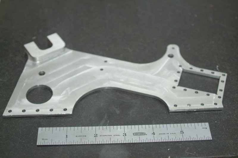
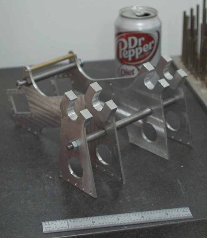
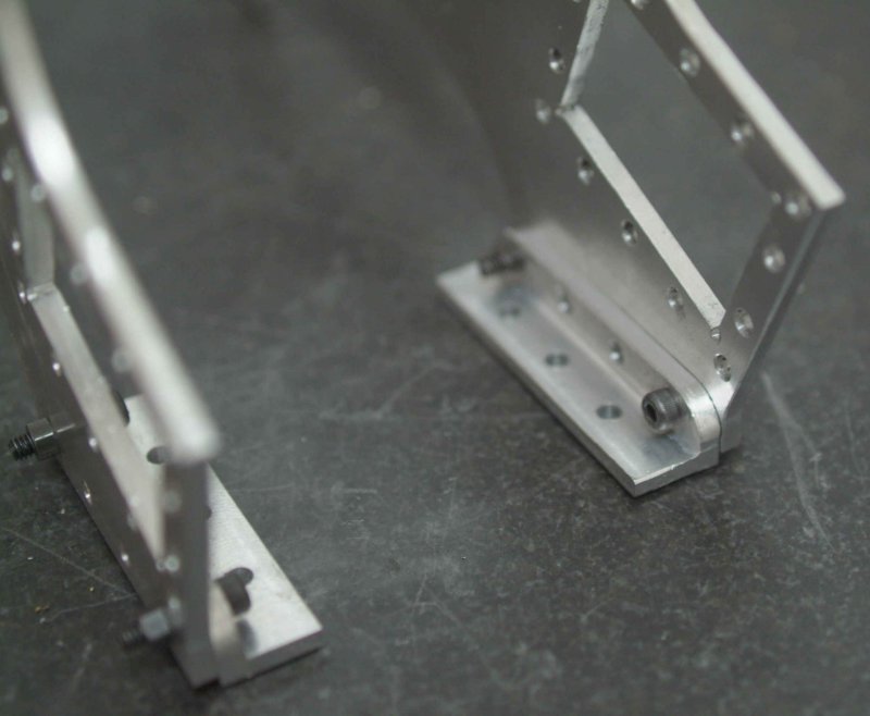
Today was the most shop time I've put in for quite a while: over 7 hours. Too much like work?
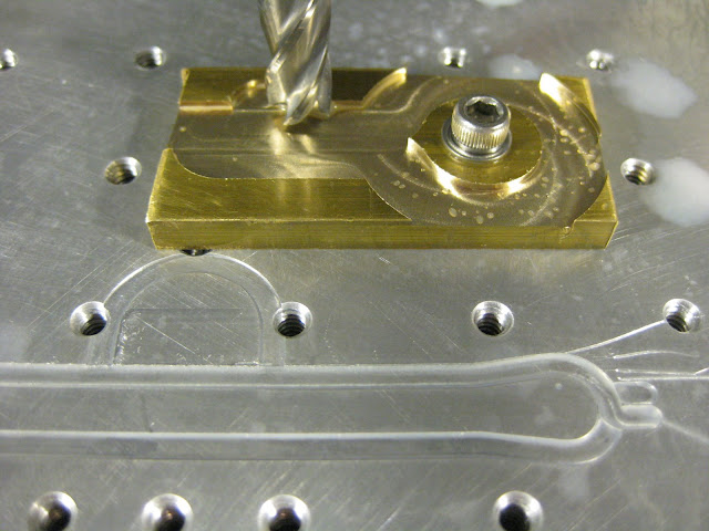
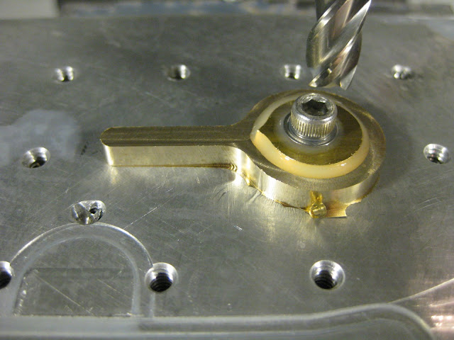
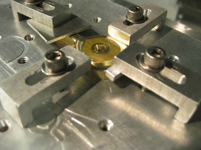
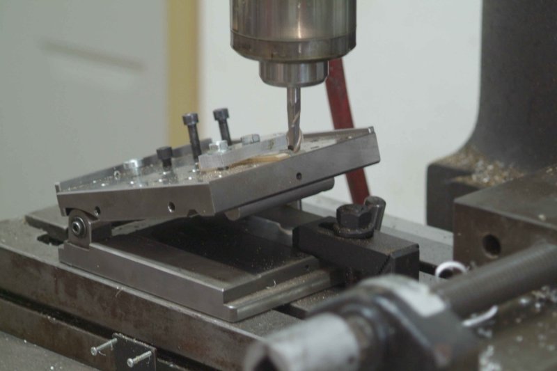
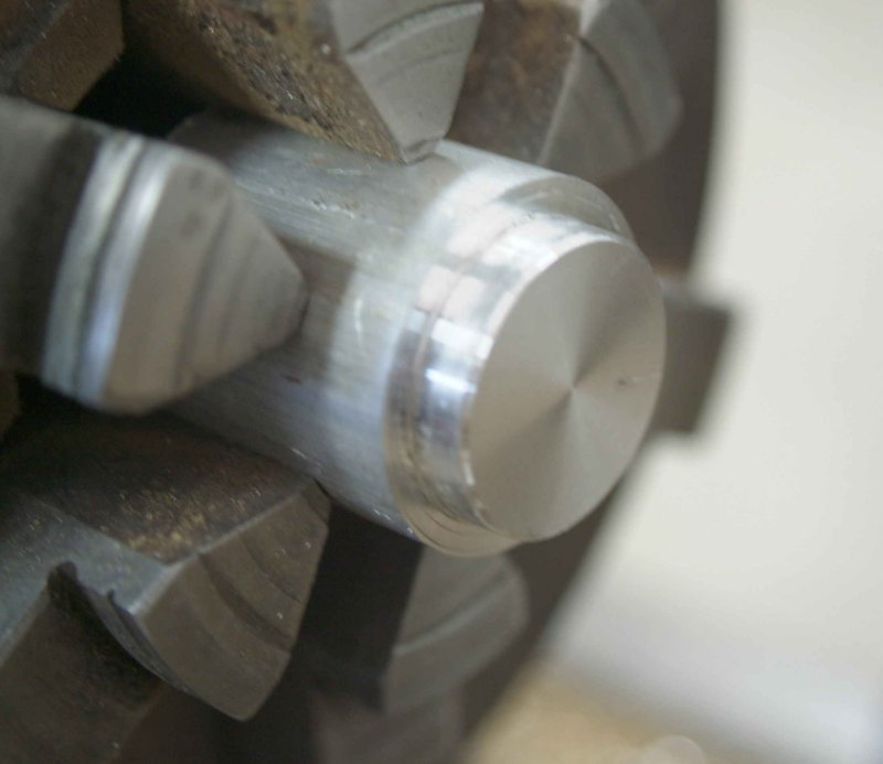
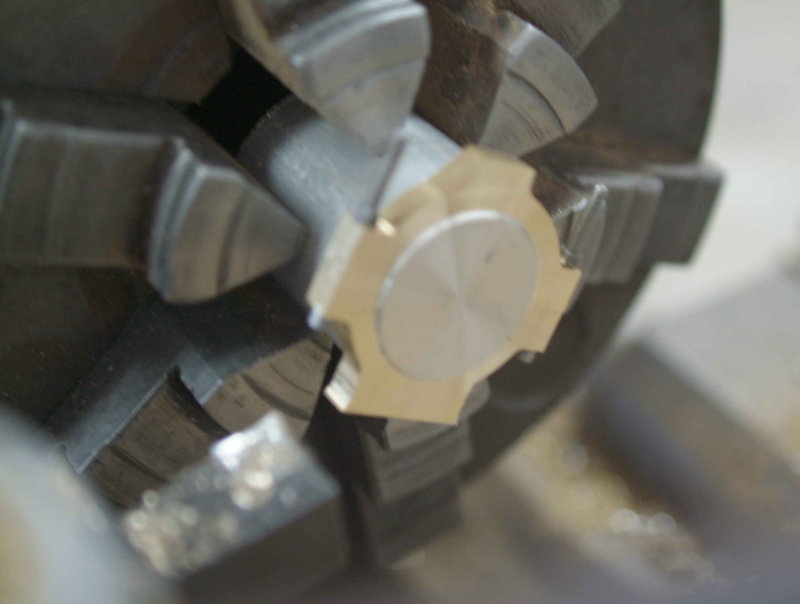
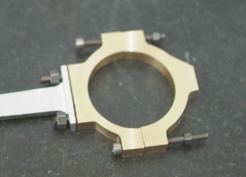
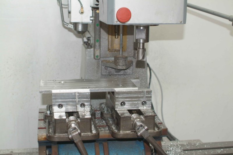
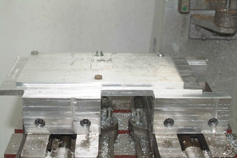
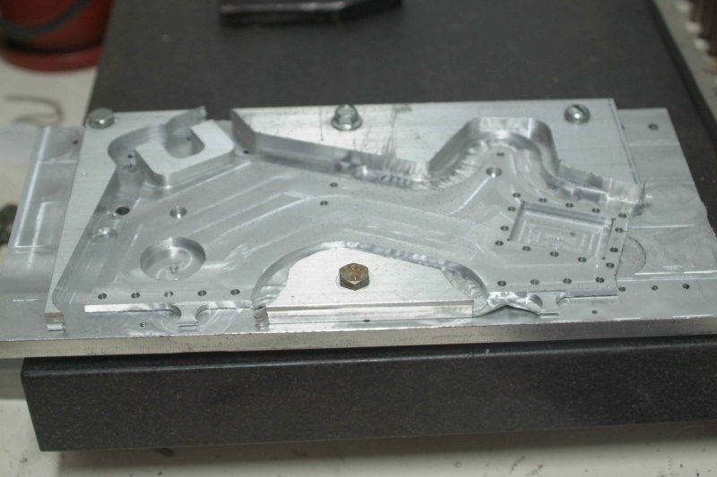
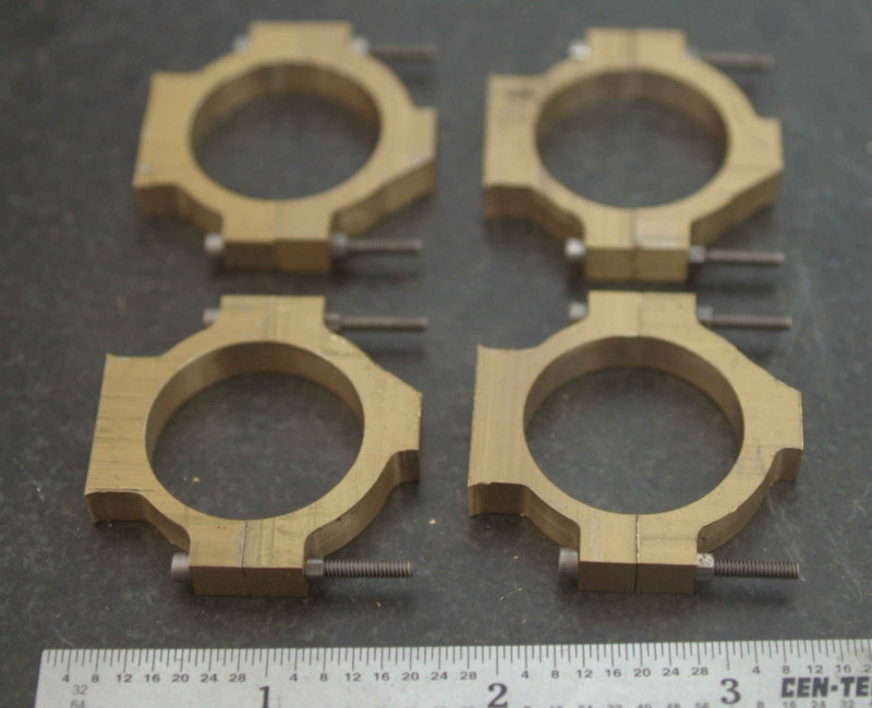
The first task was to mill out the eccentric bores. I did a "circle mill" on the CNC mill rather than use a boring bar. I expect this will be accurate enough, although there was a few thousands variation after the operations were done. I suspect the brass spring back a bit after being compressed by the vise.
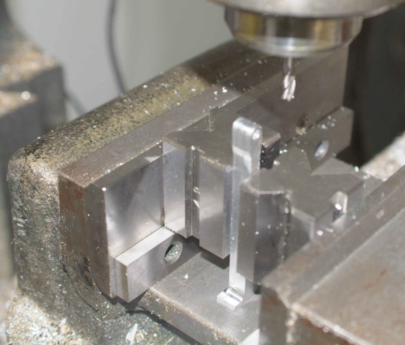
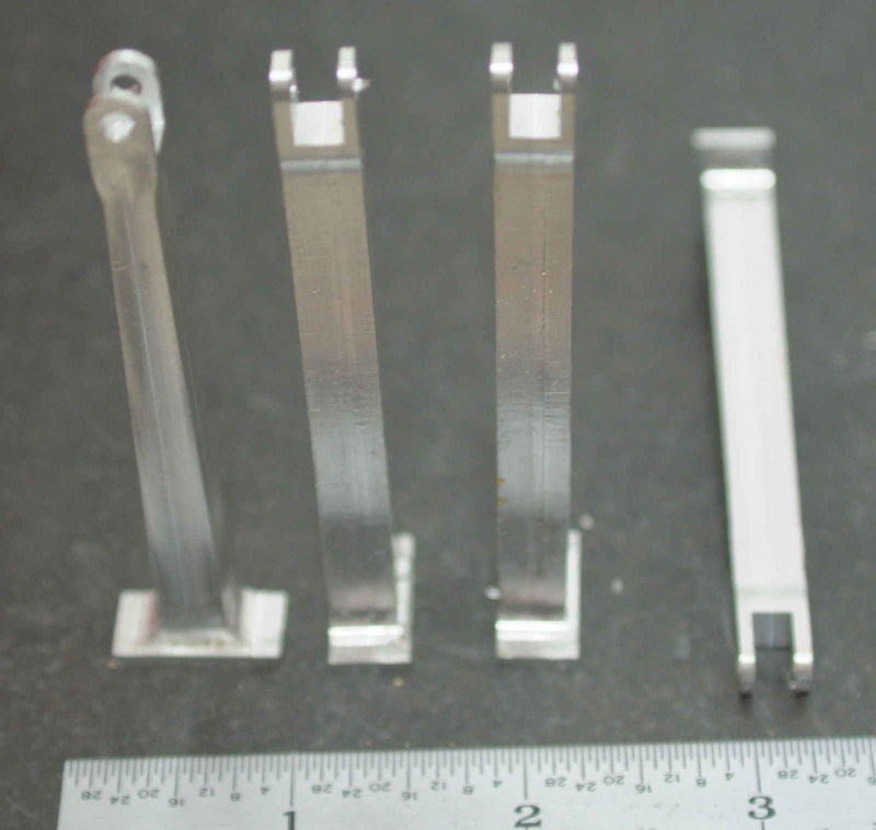
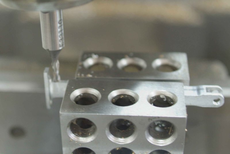
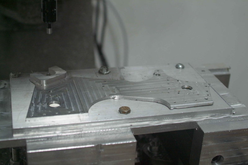
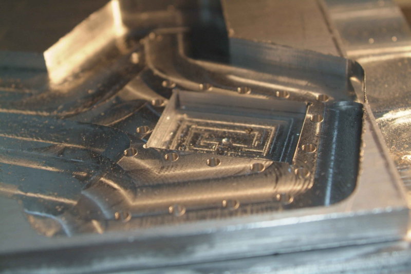
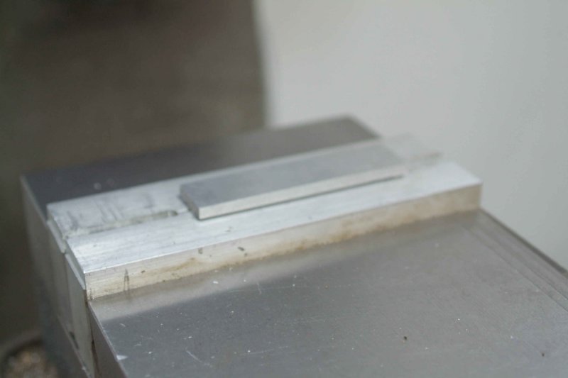
Next I decided to tackle the eccentric rods, which are possibly the trickiest parts to make of all. The first operation was to CNC mill the side profile .200" deep in some aluminum. I did two of them in some scrap pieces, and the other two in some material I cut to size.
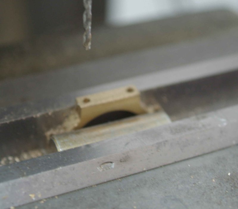
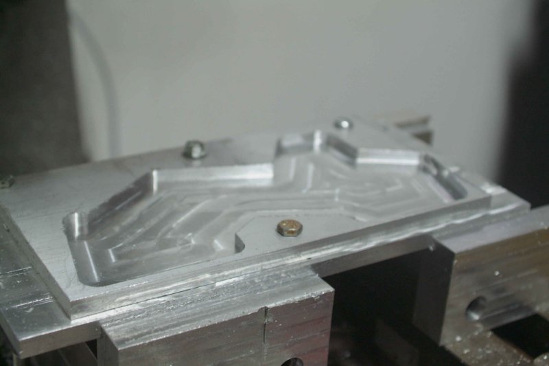
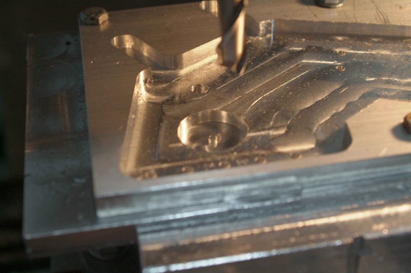
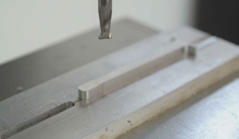
Next I milled a pocket in the vise's soft jaws to match the profile. Broke one end of a 2-eneded 1/6" carbide endmill taking too deep a cut. the pocket was milled .125" deep. Now I could invert the work pieces, hold them precisely in the vise, and mill the other half.
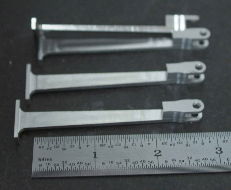
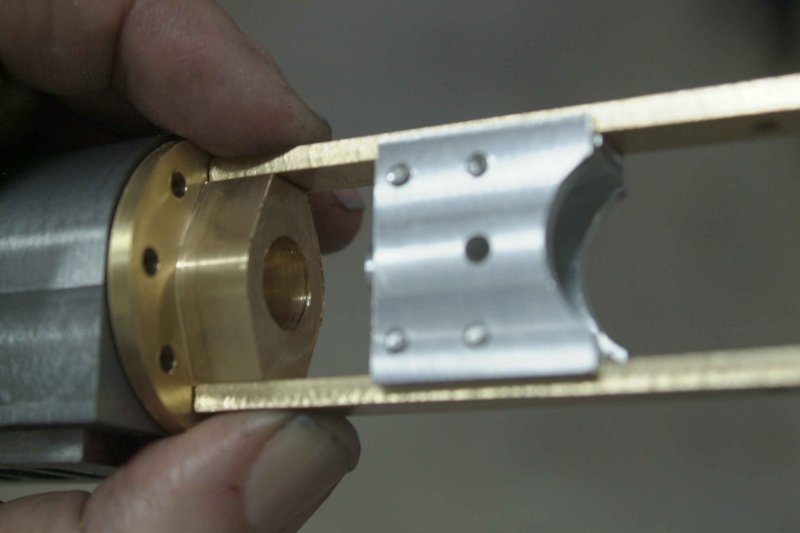
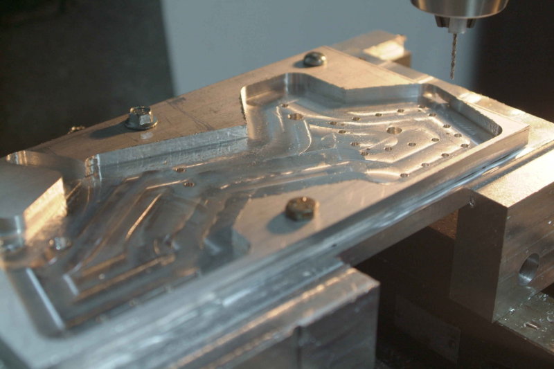
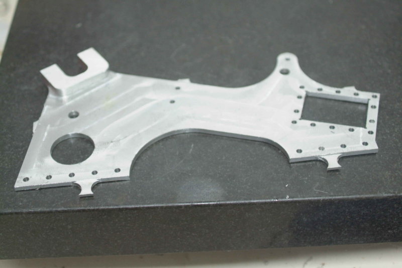
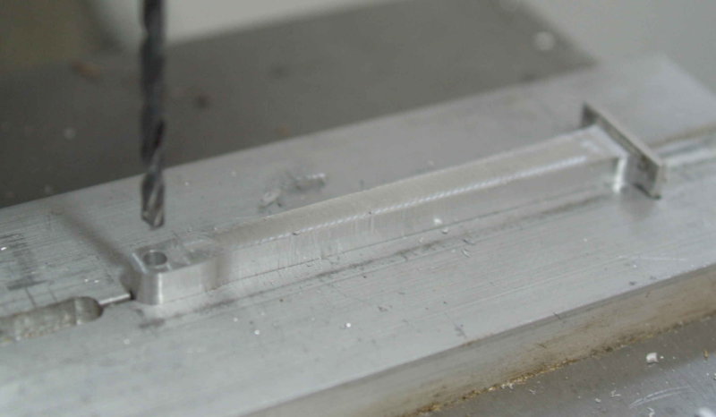
Finally, with the rod held in the pocket I drilled the 1/8" hole where it will connect to the expansion link.
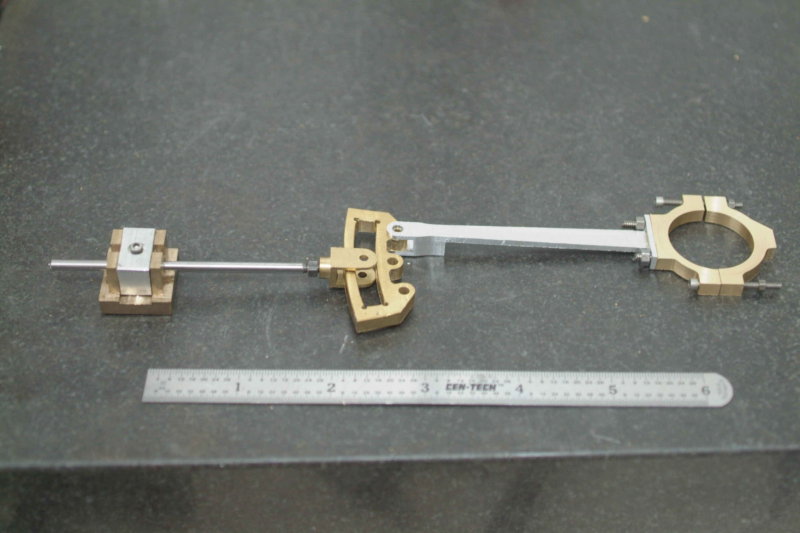
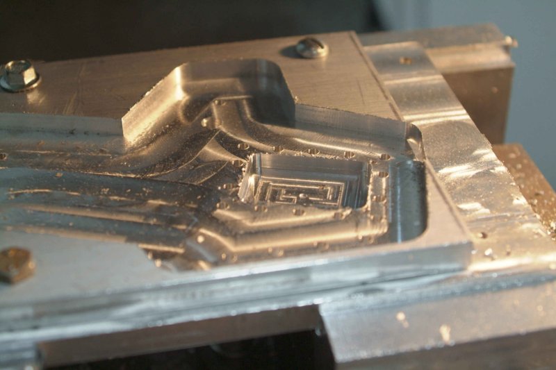
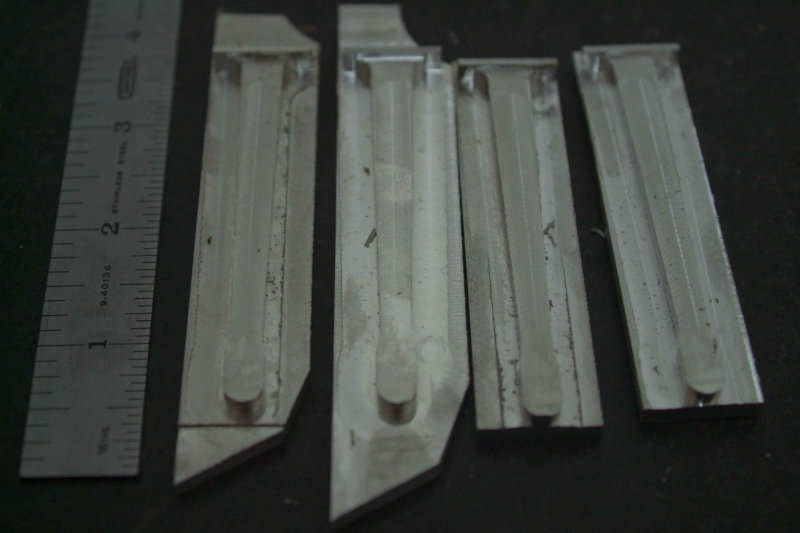
Here's the stopping point for the night.
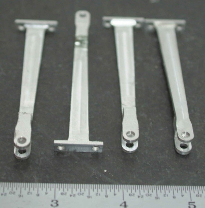
Still to do:
1) Mill the top profile
2) Mill the slot for the expansion link
3) Drill mounting holes for attaching to the eccentric strap
The first task was to mill out the eccentric bores. I did a "circle mill" on the CNC mill rather than use a boring bar. I expect this will be accurate enough, although there was a few thousands variation after the operations were done. I suspect the brass spring back a bit after being compressed by the vise.
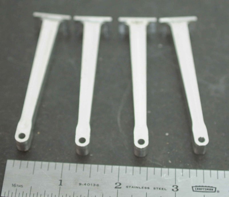
Next I decided to tackle the eccentric rods, which are possibly the trickiest parts to make of all. The first operation was to CNC mill the side profile .200" deep in some aluminum. I did two of them in some scrap pieces, and the other two in some material I cut to size.
Next I milled a pocket in the vise's soft jaws to match the profile. Broke one end of a 2-eneded 1/6" carbide endmill taking too deep a cut.
the pocket was milled .125" deep. Now I could invert the work pieces, hold them precisely in the vise, and mill the other half.
Finally, with the rod held in the pocket I drilled the 1/8" hole where it will connect to the expansion link.
Here's the stopping point for the night.
Still to do:
1) Mill the top profile
2) Mill the slot for the expansion link
3) Drill mounting holes for attaching to the eccentric strap