ET Westbury Side Paddle Engine

Home Model Engine Machinist Forum

Help Support Home Model Engine Machinist Forum:

This site may earn a commission from merchant affiliate links, including eBay, Amazon, and others.
kvom I didn't follow your work (and the whole forum) for some time, but your progress with CNC is tremendous!
this engine will be lovely
great job :bow:

 
Thanks for lookig ariz.

Today I decided to try to finish the first conrod, so after a much needed vacuuming of the machinery I set up the Monarch's taper attachment. Setting the little indicator on the 2-degree mark, I measured the actual taper angle as calculated from the XY DRO reading: 2.02 degrees, close enough!

After cutting the taper as close to the ball end as possible, I gave the shaft a quick polish with some 320 grit paper and than Scotchbrite. On this machine it's better to cut a taper toward the large end to take up any backlash in the crossfeed screw.

large.jpg


Earlier I had been worried about whether I could easily clamp the conrod vertically to drill the mounting holes and mill it to length, as it's over 1" longer than the jaws are deep. Luckily the vise jaws overhand enough to do so.

large.jpg


Finished with the big end bearing attached:

large.jpg


I thought it interesting to find that Reeves in England still sells casting for this engine (at 550 pounds, $800 :eek:). Their website didn't saw which parts are included.
 
I won't tell my brother you made the conrods out of brass. ;D
Don
 
Great looking con rod Kvom! :bow: Thanks for posting the process. I may give that a try on my next build.

Cheers,
Phil
 
Yesterday I made the second conrod taking advantage of lessons learned in making the first. The main change on the lathe was turning the shaft to 1/2", the diameter of the ball end, rather than the final major diameter of 3/8. So after cutting and filing the ball as before, I could place the shaft into a 1/2" 5C collet and the square collet block.

large.jpg


The 4.10" workpiece was just long enough so that the ball and part of the end were visible. Then I was able to mill flats on both ends, taking 1/32" off the ball and .200 off the end. After drilling and reaming the hole in the ball, I could flip the collet block and mill matching flats on the opposite sides.

large.jpg


Next I reversed the piece in the collet so that the large end was fully exposed, and used the height gauge on the surface plate to set the milled flat horizontal:

large.jpg


Now I could mill parallel flats to form the sides of the large end of the conrod. Then it was back to the lathe to reconnect the taper attachment and turn the shaft taper as before.

The remaining tasks were to mill the large end down to final length and drill the mounting holes. I discovered that it was easier to clamp the piece between two parallels than to use the tops of the vise jaws. In order to keep the parallels tight against the jaws, I inserted some pieces from my gauge block set in the opposite end.

large.jpg


Final result:

large.jpg


I goofed off all afternoon, so after dinner I decided to knock out the 4 cheek plates of the crossheads.

large.jpg


The CNC milling/drilling took only a half hour. Squaring the pieces, milling the jaws, and tapping took a couple of hours altogether. While the 5-40 SHCS are good for now, I think either studs/nuts or hex head screws will look better in the end.
 
I was supposed to go on a 2-day offroad event, but tweaked my back and decided it was not for the best to go. Since I can stand without discomfort, I spent the afternoon in the shop. Today's goal was to make progress on the cylinder covers.

Having obtained a length of 1.5" brass rod, the process on each of the 4 covers was to start on the lathe:

1) face
2) facing cut to create a .75" spigot .06" deep, to serve as a seal for the cylinder bore
3) part off

The rest was done on the CNC mill. A 1.5" round pocket .100" deep was milling in the soft jaws of the vise to hold each cover and to ensure that each was centered. From then on it was a matter of milling and drilling.

The end result of the days's effort is shown here:

large.jpg
 
This afternoon's effort was to make the two slide-bar brackets. These attach to the inner frame and secure the far end of the bars on which the crosshead slides (the other end of the bars attach to the cylinder cover).

large.jpg


The machining sequence was as follows:

1) square 2 pieces 1x1.5x.375 inches on the manual mill
2) CNC the main "pocket" using a 7/16 endmill
3) CNC the inner profile with a 1/8" endmill
4) Back to the manual mill to make the outer 45-degree cut.
5) Drill the clearance holes for the 5-40 screws that will attach the bars.

To be done: file the edges of the inner slots where the bars attach, and drill/tap holes in the sides to attach to the frame. This latter operation will be done once the positions of the brackets are known exactly (i.e., the crosshead slides smoothly between the bars with no binding).
 
Latest parts made are the two valve forks that connect the valve rod to the die block, which slides inside the link.

large.jpg


The screws show where the threaded valve rod attach via 5-40 threads, plus a lock nut for adjusting the valve travel.
 
Looking good Mr Kvom I can remember making these parts as if it was last week,the way you are going this will be up and running by the time I'm home from hols.
Don
 
Things are going to slow down soon, Don. At the end of the month I'll be hauling the Jeep out to Utah for a week's offroading in Moab, then staying another week out there for a family vacation. So along with the time for driving out and back that'll be 3 weeks with no shop time.

I recently discovered this website http://www.donashton.co.uk/index.html which describes how these links work, along with some good animations.
 
Thanks for the site,I've sent it along to my Bro.
Cheers Don
 
Today's parts are the valve rods and the valve buckle. Rods are 1/8" drill rod threaded 5-40. For the setscrew on the buckle, I drilled and tapped for a 2-56 screw and countersunk for a SHCS.

large.jpg


Thanks for the link to Don Ashton's website. I have his book on valve gears and I highly recommend it.

The web section on Traction and Marine gear states the problem with marine engines they have short rods and this makes the error more pronounced. The type of gear you are modeling is direct Stephenson. To get this to work with Dockstader's valve gear program took me a bit to figure out. I am a Shay fan which uses the very same type of valve gear and launch links.

If anyone is interested in direct Stephenson gear and valve gear programs I can start a new thread on the subject and not hijack this one.

Dan
 
My task for the past two days was to make the two cylinder gland nuts. No CNC work for these. :p

I had a short piece of 3/4" diameter brass, so the first task was to turn down the outer ends to 1/2" and thread them 1/2-28. By doing the threads at each end I was able to have a nice amount of material held in the lathe collet, and as well I knew the DRO DOC settings for the second thread once the first was done.

large.jpg


I had previously tapped an aluminum "nut", so I had something to test when the thread was good. Next each end was parted off:

large.jpg


The nut now comes in handy again. I parted off each end, then threaded the gland into the nut so that the parted end could be cleaned up:

large.jpg


Now the nut/gland/collet were transferred to the hex collet block on the mill to drill the 6 radial holes for tommy bars (used to tighten the nut onto the gland):

large.jpg


The drilled nuts:

large.jpg


The hole for the piston rod will be drilled with the nut screwed into the cylinder cover to ensure concentricity.
 
Kvom,

I have been following this with great interest and it's really looking good :bow: :bow: That CNC is sure great for making more than one of the same part, as are your manual skills with the gland nuts. ;D

Best Regards
Bob
 
Bob,

I appreciate the support; thanks for your comments.

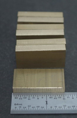
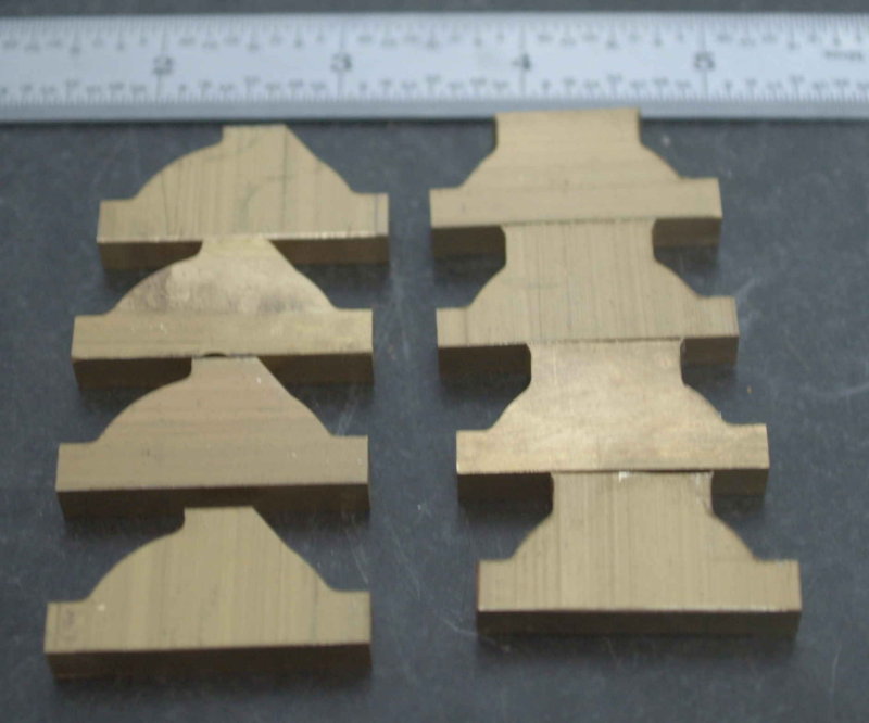
Over the past three days I've been trying to make progress on the eccentric straps, all the while having life get in the way. I recently found a slotting saw via Craigslist, so it was a big help in cutting out the blanks for the straps from some 1/8' thick brass sheet. Each of the 8 pieces was machined to 1.5x.75". All three dimensions are slightly larger than the final target size.

medium.jpg


I should have made a spare as I later ruined one and had to go back and make another. :'(

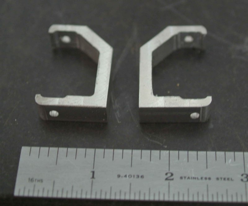
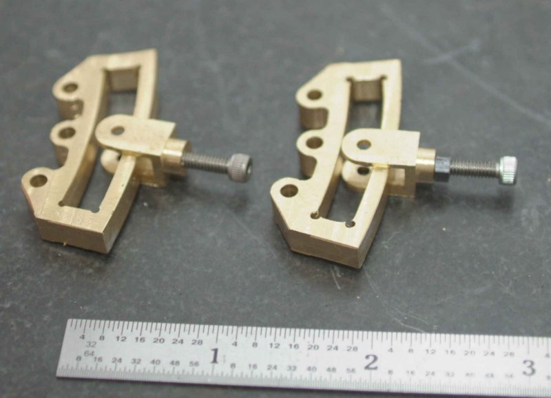
Then each piece has a profile cut on the CNC mill: roughing cut with a .25" endmill, and a finish cut with a 1/8" endmill. I had previously made another but it was messed up since I had a poor design for clamping in the vise. This time I left a flat on each side; on the forward side this will later be milled away.

large.jpg


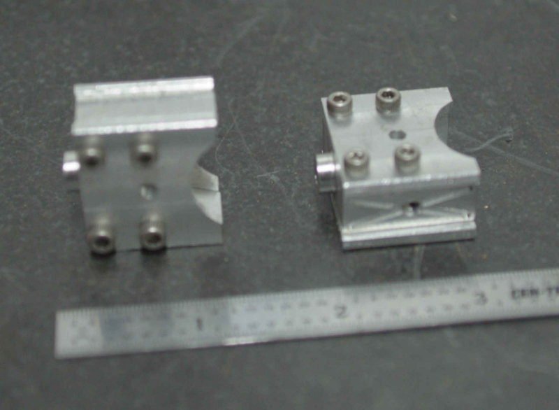
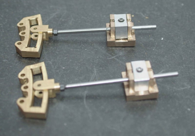
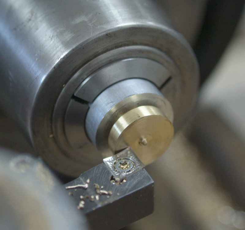
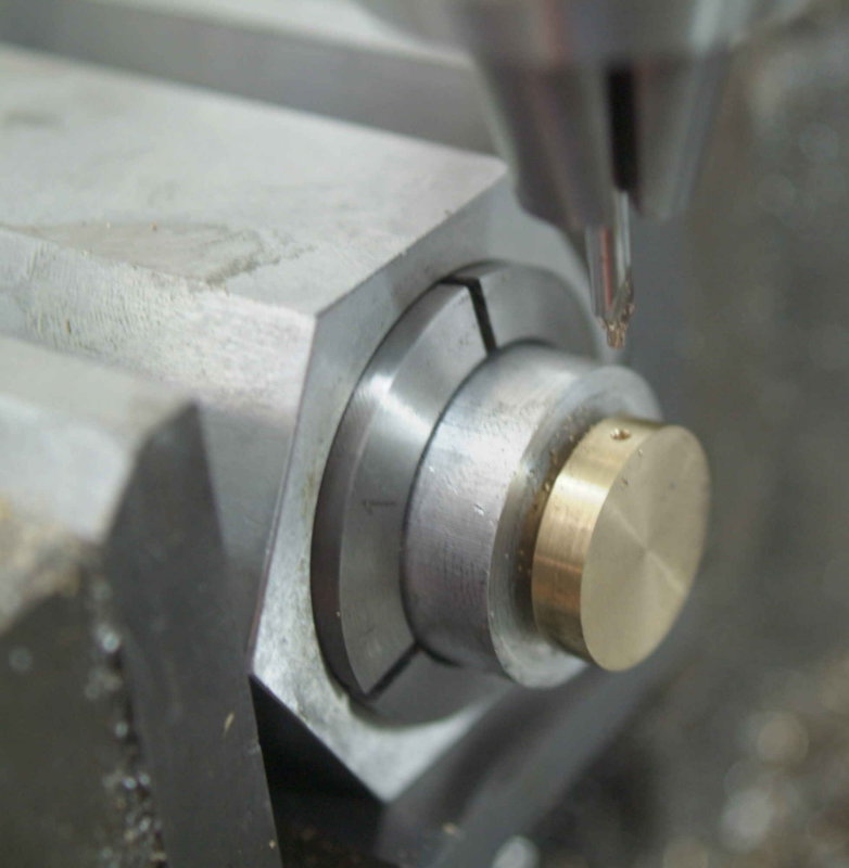
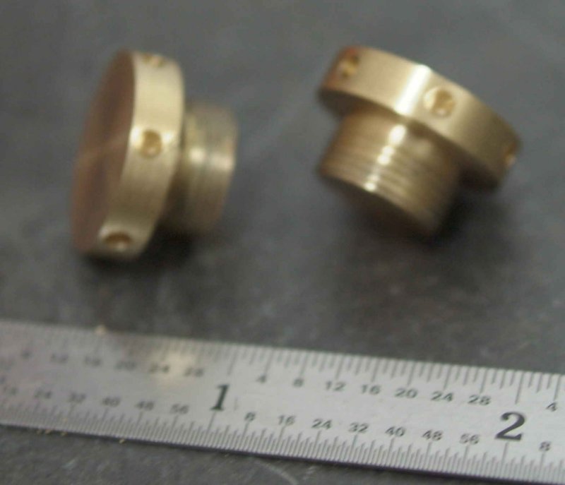
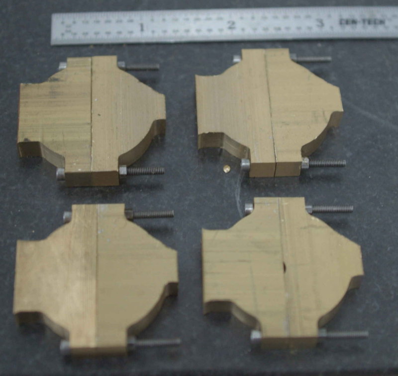
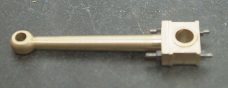
Then the mounting holes were drilled. Here I used softjaws on the vise to machine a holding pocket. This allowed the hole spacing to be quite precise. Now I'm able to screw the two halves together with 2-56 screws and nuts. The screws will be trimmed at some point.

large.jpg


Remaining to be done:

1) Bore 1" diameter hole in each to contain the eccentrics
2) Mill straps to 3/16" thickness (or to match slot in the eccentric disks), and remove 1/16" from rod mounting surface
3) Drill and tap mounting holes for the eccentric rods (4-40)
4) Finish profile and drill oil hole
 
Eccentric straps are some of my favorite parts to see.
A classic engine part.

2-56 screws! Small!

I went back through the thread to remind myself of what you're building.
Very very nice project.
 
It's coming along well, K.
There's an odd flat on one half of the eccentrics. (I don't mean odd as in bad, but as in different.)
Are those for oil cups?

Dean
 
The "flap" will be milled off to make an angle, with the oil hole drilled into it. On the plans there's no cups, but they could be added.
 

Latest posts

Back
Top