ET Westbury Side Paddle Engine

Home Model Engine Machinist Forum

Help Support Home Model Engine Machinist Forum:

This site may earn a commission from merchant affiliate links, including eBay, Amazon, and others.
Kvom,

Looks to me that you will end up with one fine looking engine.

SAM
 
Sam & Larry, thanks for your comments.

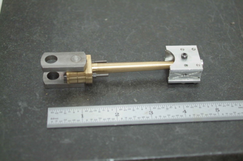
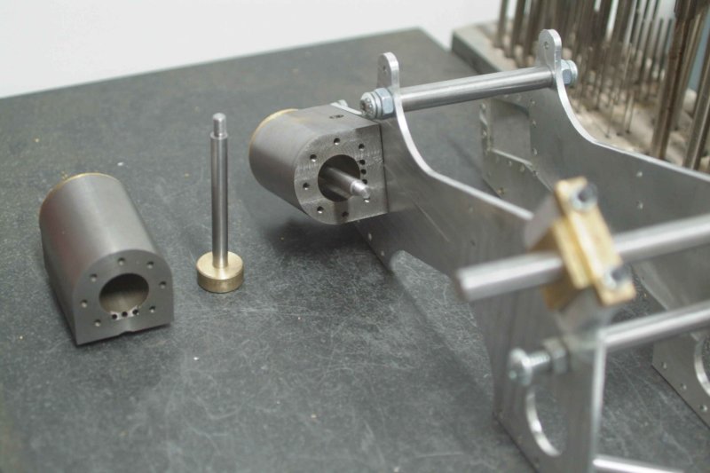
Today I started on the cranks, and did not have a good day. Here's the photo evidence:

large.jpg


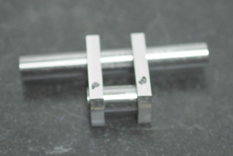
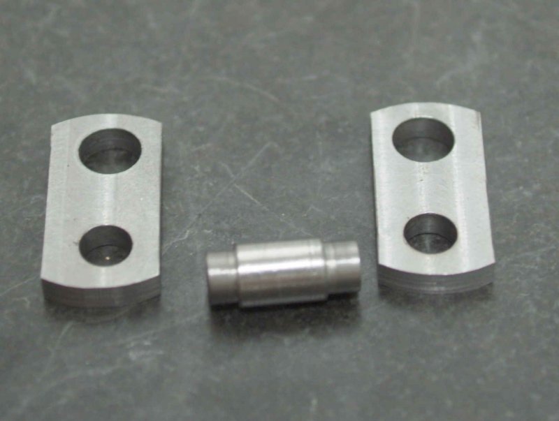
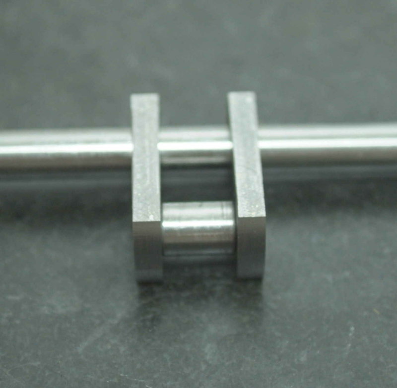
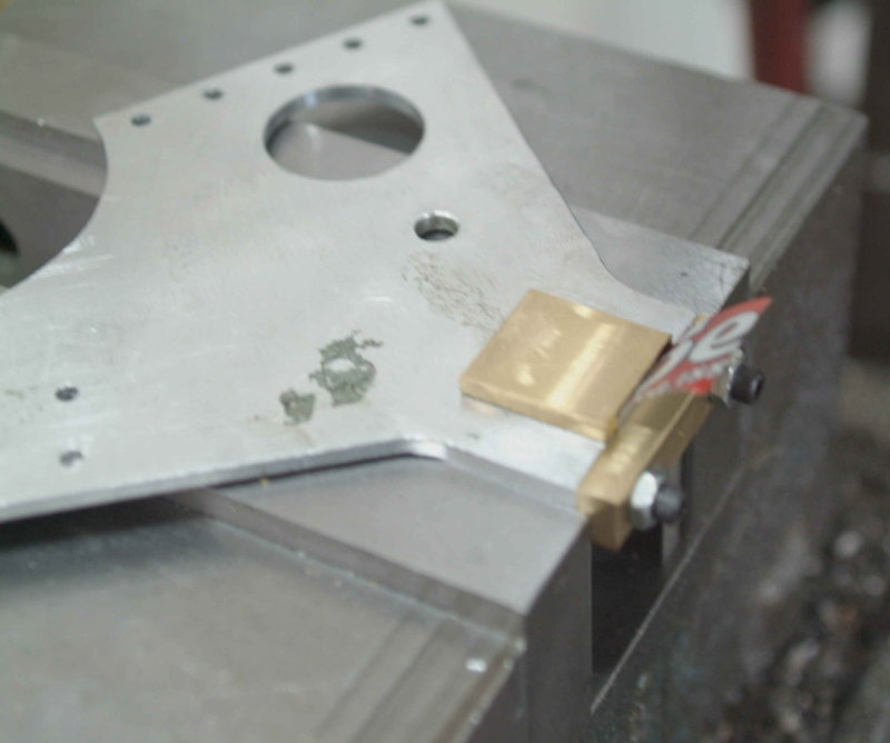
The shafts are all 3/8" drill rod. The webs are 3/16" thick and need to be separated by 1/2". After drilling and reaming the webs .001" oversize, my process was to hold the webs and the crank pin together in a vise with a .500" gauge block clamped between the webs for spacing. I would then fix the crank pin to the webs with 1/16" roll pins.

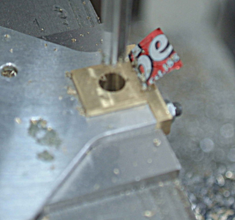
I had two errors with this plan. First, I had made the crank pin slightly too long, so that when I clamped the vise the webs and the gauge block were a bit loose. I ended up with the webs about .04" too close together. The second error was where I drilled for the roll pins, which need to be in the ends of the web rather than the side. With the pins where they are the webs can move slightly side to side around the roll pins.

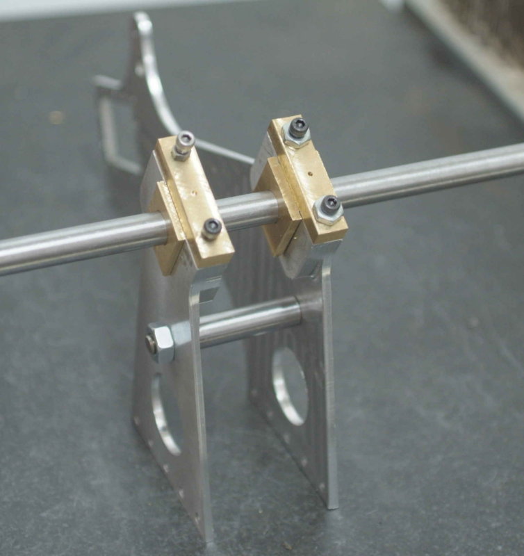
I also discovered that the crankshaft pieces I had cut will be hard to get straight, as the oversize hole and thin web make it possible to move slightly.

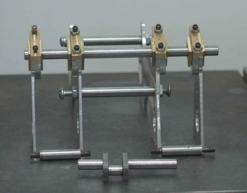
So my rework plan is as follows:

1) Make the crank pin slightly less wide than the width of the crank, allowing use of the gauge block to set the web separation.

2) Make the crankshaft one piece and use for aligning the webs.

3) Secure both the crank pin and crank shaft with loctite and let set

4) Drill and insert roll pins and the ends of the webs after the loctite dries.

5) Machine out the center section of the crankshaft.
 
The only comment i would make on your rework plan would be to use solid pins instead of roll pins,they tend to work loose,but then maybe the loctite will hold.The solid pins will certainly look better after filing flush.
Hope you don't mind me having my say Kvom.
Don
 
One thing you might consider doing is to shoulder the crankpin. The bearing area would be the correct size, but where it fits the webs, it would be reduced by a small amount, say 1/16" on diameter.

Doing this will assist lining up the webs perpendicular to the crank pin and will also ensure the webs are kept the correct distance apart. Loss of strength would not be an issue.

Dave
The Emerald Isle
 
Thanks for the ideas.

Dave, I like the plan to shoulder the pins. If I do that I could leave the part that is in the webs slightly short, make the webs from steel, and then weld the pins to the webs. I'd then grind the weld flush afterwards. Thoughts?
 
No no no, pinning the webs to the shafts is the best.
Don
 
I started to remake one of the cranks today, this time using some 12L14 for the webs and shouldering the pin:

large.jpg


I have put some loctite on the pin ends to set up until tomorrow. The total width measured from the outside of the webs is .04" oversize. This is "semi" on purpose as my rod ends are .03" too wide. I think I can safely take off .02 from the outer side of each web if needed.

large.jpg


I won't fix the crankshafts until the engine is ready for a trial fit.

 
Or you could increase the frame spacer length,tell you what I did on my Gerrys beam engine,I laid the 2 shafts in v blocks on a good flat surface with the ends flush with the inside of the webs,loctite, left to set then pinned,came out true much to my supprise.
Don
 
You didn't waste an time getting the new crankshaft sorted out!

The shouldered crankpin setup looks good and I feel sure that Loctite and tapered pins will be better for your application than trying to weld the bits together.

Dave
The Emerald Isle
 
Thanks for the hint, Dave. Still have the second crank to make if this one works out.

Don, I know that the staybolt lengths are not critical and that I can separate the outer frame from the inner more than the plans call for. However, in order for the piston rod, conrod, and crank to line up I am constrained by the distance of the centerline of the cylinders from the inner frame surface. If I need to move the crank and conrod centerline closer to the frame, I would need to reduce the widths of some combination of the bearing, inner crank web, or rod end. I guess it it also possible to use a "spacer gasket" to move the cylinder outboard a bit, but I don't think that would gain much.

I have quite a bit of excess material left in the bearings and the crank web, so hopefully they will be sufficient.
 
The parts are looking great to me.
Also, I appreciate various bits of learnings and techniques demonstrated here.
 
Need help finding plans.New to site so unfamiliar with navigation(??????)
 
The first task today was to drill and pin the crank webs to the pin. This went well. I started the roll pins by tapping with a hammer, but then pressed them in fully with the vise jaws. One of the conrods was test fitted:

large.jpg


Next I undertook drilling the first pair of bearings.

Here's the setup in the milling vise, with the inner frame being clamped by the hornblocks.

large.jpg


There is a couple of thousands play between the bearing and the hronblock, so I used a shim from a soda can to clamp down the bearing with the retainer plate. Note that I obtained the center from measuring the inner edge of the hornblock.

Then drilled and reamed:

large.jpg


Then the the same with the outer frame, although clamping in the vise was trickier because of the curve leading into the hornblock. Still it seems to be all good as the drill rod passed through the assembled frames turns pretty easily:

large.jpg


Before leaving the shop I set some drill rod for the crankshaft into the webs with loctite; next time, after it cures, I'll pin it to the webs. Also need to make the other crank and drill the other two bearings.
 
Spent a good part of the afternoon in the shop. The first task was to drill and pin the crankshaft to the crank webs, then mill out the portion of the shaft between the webs. Then I finished drilling the bearings for the other two frames, allowing a test setup of the four frames. Here's the result, including the crank:

large.jpg


The good news is that with the two center staybolts in place, the 3/8" length of drill rod turns smoothly while passed through all four bearings. \

The bad news is that the holes for the outer staybolts in the outer frames seem to be ~.04" higher than in the inner frames. I checked my CAD drawings and they are correct, so I have no idea how they became displaced. I can still install the outer staybolts, but that causes the frames to flex slightly and jam the alignment rod. I will enlarge the holes in the inner frames slightly to correct this. As shown in the photo, the height of the staybolts varies on .004" from one end to the other, so the engine is quite level side to side.

Now that I have a crank and can connect the frames for testing fits, I proceeded to mount one of the cylinders to get an idea of how much the bearing sides will need to be trimmed. To do this, I needed to finish fitting the previously turned piston to that cylinder.

That's when I discovered that the conrod threads were crooked on one end. I had cut the threads with a die on the lathe, but that wasn't good enough. So I proceeded to make two new piston rods with the 10-32 threads on each end single-pointed to ensure they are concentric. Once they were done, I needed to remake the piston, which needs to be turned "in situ" on the piston rod. So this meant facing/turning/drilling/tapping some 1" brass rod, then parting off and screwing onto the piston rod. Then the final diameter is turned with the piston rod chucked in a collet.

large.jpg

 
Hi kvom,

nice to see the paddle engine growing (and to see that there some other who build it :) )

my engines are little bit other than the shown one by don-tucker:

Diagonal-800x600.jpg


i was astonished at first run of the less steam consumption and one of my engines works in paddle duck :)

When i meet the ship builder i will see if i can make a small video of it in action

Frank
 
Frank,

It's good to see you pop in again. I was looking for your missing photos on the Paddleducks site before I started work, and someone wrote that you were ill. I hope you're back into modelling again. I'd like to see more pics of your engine from different angles, just to get some ideas for finishing mine (esp. the plumbing). It won't look as nice as yours for sure. I love the way you did the cylinder cocks, something mine won't have.
 
Hi kvom,

the server where the pictures has been stored has changed by another "member" of our small group after a crash ...
And they don't find the backup i've made some weeks before this crash ...

I've send you a private message - maybe thats a solution for you :)
You also may share that photos here - there isn't a problem from my side

And:
i'm not right up at all - but there's a light :)
(one problem just mostly survived the next one comes without a moment for take breath :-( )
at the moment i'm only planning some projects - some things like a 72° watercooled V10 with double DOHC (FIA-style)
and a roots charged 6cyl boxer ...

Frank
 

Latest posts

Back
Top