ET Westbury Side Paddle Engine

Home Model Engine Machinist Forum

Help Support Home Model Engine Machinist Forum:

This site may earn a commission from merchant affiliate links, including eBay, Amazon, and others.

kvom

Well-Known Member
HMEM Supporting Member
Joined
Jun 4, 2008
Messages
3,285
Reaction score
630
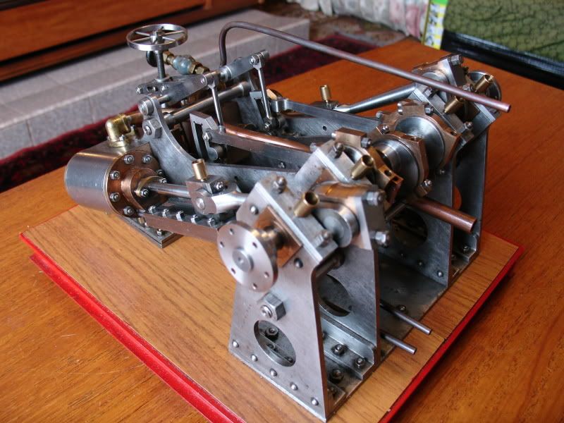
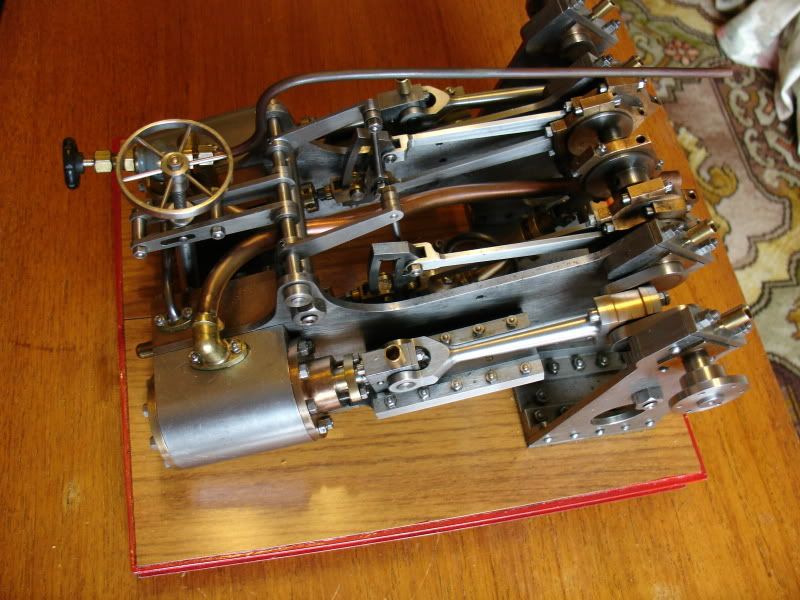
This build will be a pretty long term project, so this is a holder thread. I will be using this project as a "training" effort for my new CNC mill, so expect lots of do-over parts, broken tooling, etc. The plans were originally published in ME magazine in late 1955, and have now been released to the public. A copy of the articles has been posted on this website.

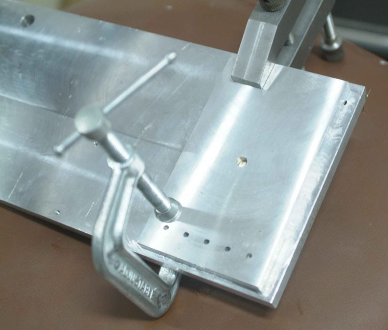
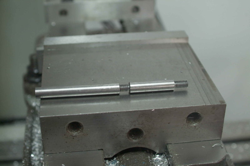
My first attempted part was an outer main frame in aluminum and was not a success. I think I learned enough from this effort to succeed on a re-do, plus the other 3 frames as well. I don't have stock for these at present so have moved on to other parts. The first parts actually made are one outer and one inner stay bolt, turned manually on the lathe from 3/8" drill rod. Once again I ran out of stock so making the other 2 staybolts will be deferred.

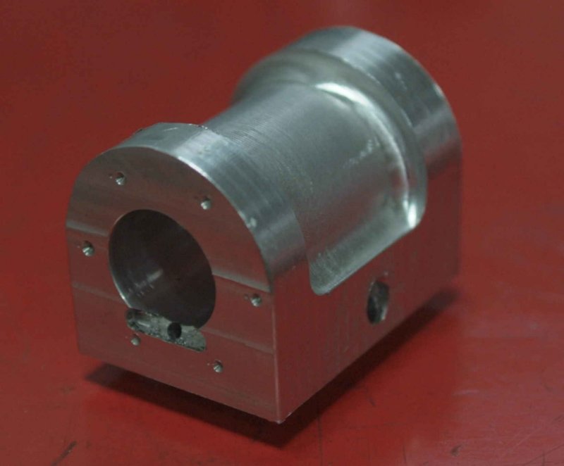
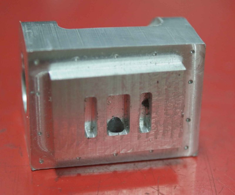
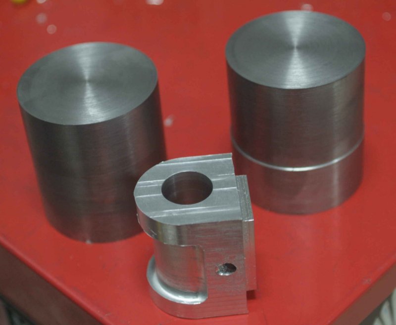
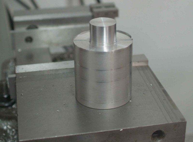
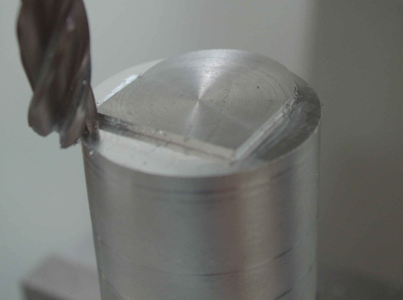
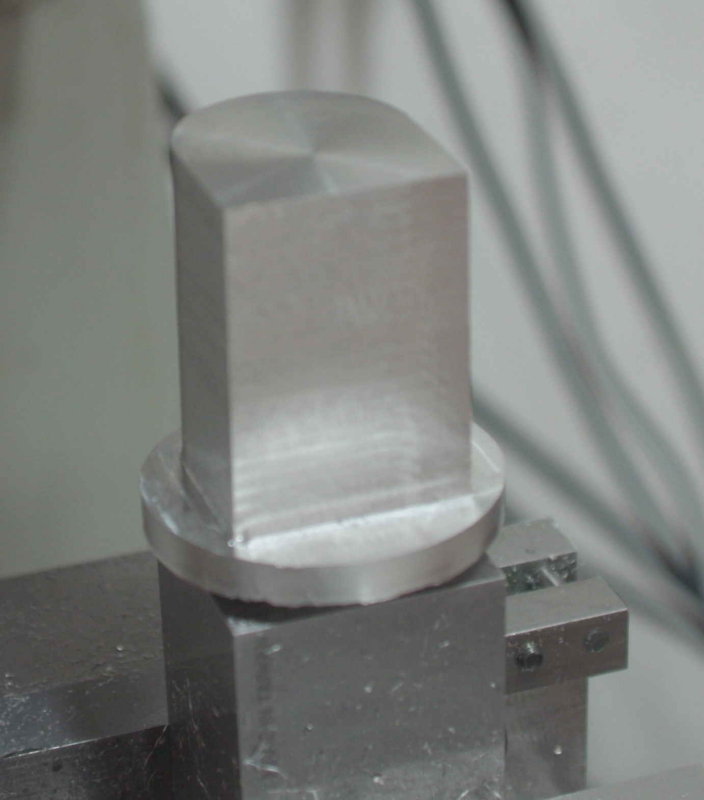
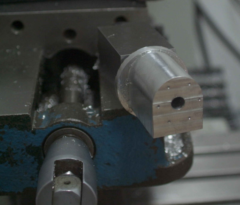
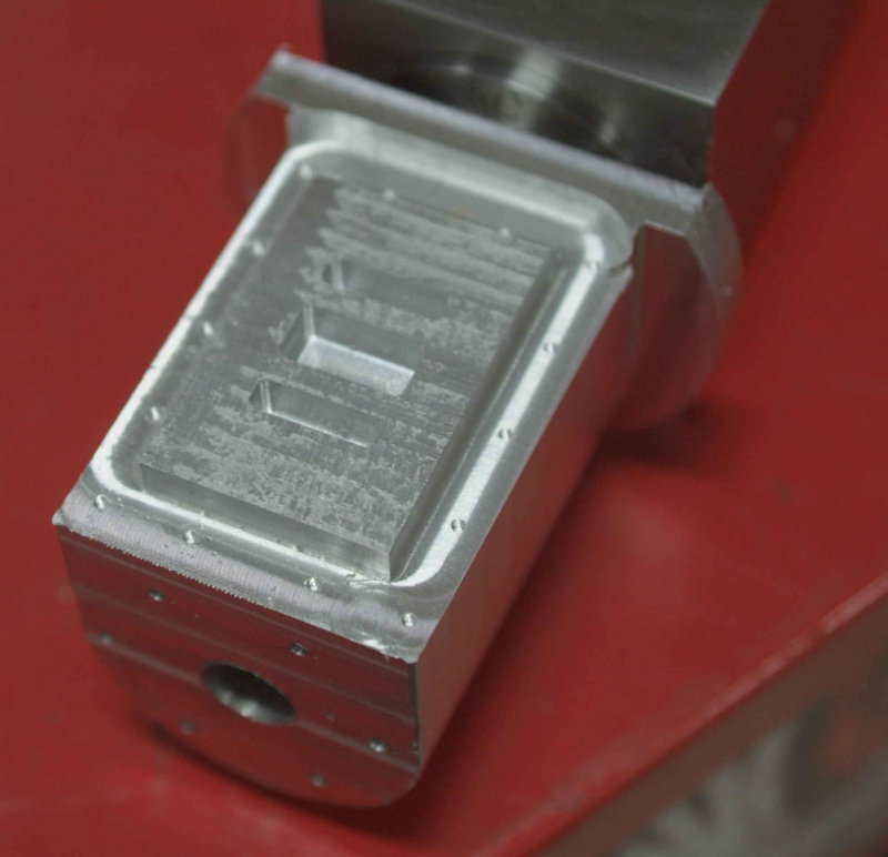
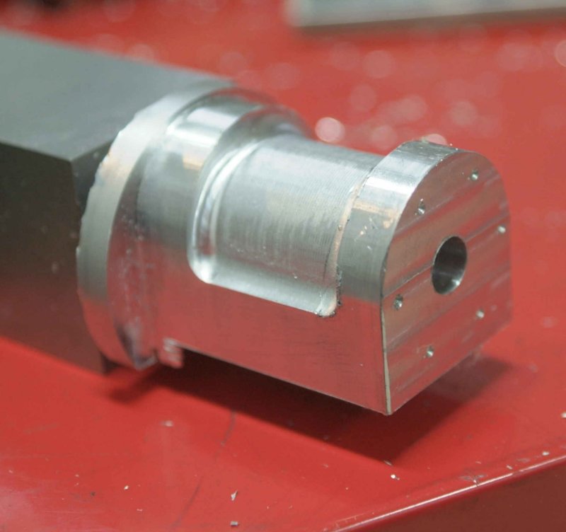
In have been looking at attempting the cylinders next. In the article the cylinders were machined from castings, which are no longer available. To make from round bar a 2.1' diameter would be needed. I don't have any brass stock large enough, but do have a large amount of 3" round 6061 aluminum. I am thinking that a brass piston in the aluminum cylinder should be workable, but would appreciate others' opnions. The engine would be run on air, not steam. Durabar would be a reasonable alternative to aluminum or brass I believe. Since the cylinder is a fairly complicated piece I plan to make the first from aluminum in any case.
 
Following a suggestion from Gail, I ordered a 12" piece of 2-1/8" cast iron from which I'll hope to machine the cylinders. Before potentially screwing up the CI, I've decided to make one from aluminum, as some of the operations are "delicate".

To start, I cut off 3" of some 3" diameter 6061 and chucked it in the lathe. I faced both ends, then turned one end to 1" diameter for a length of .75". Then I reversed the piece and chucked the piece in a 1" 5C collet in order to turn the rest to 2.25".

large.jpg


The rest of the operations will be done on the mill, holding the work in a collet block until the profile is milled out.

Here's the two staybolts I made earlier. Nothing too fancy, but it was the first chance I had to try out the insert threading tool I got from Mesa Tool a few weeks ago. Threads are 1/4-20.

large.jpg
 
Contin uing on with the cylinder, I chucked the small end in a 1" 5C collet in a collet block and clamped in the milling vise. The g-code program is to mill the cylinder profile in .05" depth increments. I stopped it after one pass to check the pattern:

large.jpg


Quite a while later:

large.jpg


I drilled the bore out as far as 3/8". Further drilling/boring/reaming will be done on the lathe later on.

large.jpg
 
kvom,

Thanks for the setup. Not CNC but I've previously done mine horizontally. next time I will try your vertical approach. :bow: :bow:

Best Regards
Bob
 
Hi kvom,is this the engine you are building
Models008.jpg

Don
 
Hi kvom,is this the engine you are building

That's the engine I'll be trying to build. Great picture! If you have any more closeups I'd love to see them as the magazine scanned photos are really dark.
 
Engine001.jpg

Models011.jpg

Engine001.jpg

Hope these help,I have a clip of it running ,can i post it the same way.
Don
 
That would be great. So far I see a few minor deviations from the plans.

A shot looking down over the centerline would be appreciated as well.
 
Models007.jpg

The mods we did was change the crosshead and con rod smallend to be more in line with marine practice and a few odds and ends.It's a beautiful engine we love it.
Don
 
Did you put in cylinder drain cocks? Any build hints?

I like the way the exhaust tubes are done.

It looks as if the inner cylinder covers are a bit different. Having 8 studs/nuts rather than 6 looks very nice.
 
No drain cocks,the crosshead guides were redesigned with one underneath instead of top and bottom,again to be more inline with marine engines.
My brother and myself built this engine about 40 years ago ,and was pretty straightforward from what I can remember.
Don
 
When built I used the plans and instructions from the ME but I do have a CD with a copy of the same on it including the paddles .I was selling it for £10 plus post on e-bay.
Don
 
The scanned magazine articles w/ plans are now public and are on this site in the plans section (along with the stern paddle engine).

Yesterday I had short amount of shop time and manages to mill the base of the trial cylinder. The 3 steam slots were cut 3/16" deep with a 1/16" carbide endmill at 4000 rpm (mill's top speed) and a feed rate of 5 IPM. I tool only .030" DOC per pass and used air to blow the chips out as it cut, along with a bit of WD40. That's an operation I wouldn't care to do manually. Slots are .5" long, and the narrow ones are 1/8" wide.

large.jpg
 
I've been fighing a chest cold all week, so not up to any long shop sessions. Today I tried a bit of an experiment, seeing how I might make the cylinder look more like a classic casting form such as the original model used. Here's the result:

large.jpg


Not having any good handle on the 3D capabilities of the CAM programs I'm trying out, I decided to develop my own g-code since the basic milling tool move is just an arc in the YZ plane. I used a 5/16 ball endmill as it's the only appropriate size ball I own. I wrote a Java program to output the G-code. Each arc covered .02" in the X direction. In was a bit conservative in the feed rate so it took 20 minutes to mill. With some tweaking the code should be able to run in less than 5 minutes.

I got my CI from Speedymetals today, so once I'm comfortable with the result in aluminum I can try to make a couple in iron.
 
I finished with the trial aluminum cylinder this morning. Milled off the extraneous bits, then drilled, bored, and reamed the bore to 3/4" on thye Bridgeport. The boring bar I have that is long enough and small enough did not do a very good job of boring (left a bit of a taper), so for the CI version I will drill to 41/64" then mill to 11/16 on the CNC before reaming.

Next I milled the chamfer in the lower lip of the bore and drilled a steam supply hole to meet the slot in the base. As per the plan, drilling at a 30 degree from vertical resulted in a "spot on" meeting. Similarly, drilled the 3/8" exhaust hole from the side to meet the central bottom slot, also at 30 degrees from vertical. With the 30-60-90 angle bar I made last year setting the cylinder in the vise was quite easy.

large.jpg


large.jpg
 
Having received a supply of metal from UPS, I continued on two fronts.

For the cylinders I got a 12" long piece of grey cast iron 2.25" in diameter. I cut off 2 3" pieces in the bandsaw, then faced and turned each to remove the external skin. The CI machined quite nicely using smaller feeds/speeds/cuts than for steel.

large.jpg


I also ordered 3' of 6061 3/8"x5" for the frames. I had found a piece of 1/2" 6061 in the school scrap bin that is just the right size for a fixture plate. I decided to try using Loctite "Super Glue" to attach the work to the plate. Since the outer frames are smaller than the inners I'll start with those. I drilled the 6 hole pattern for the frame into the fixture. The I cut 2 3" pieces giving a 3x5x3/8 raw stock to start for each. I drilled the same 6 hole pattern in each, then flycut on both sides so as go give a smooth mating surface for the adhesive. I then put some brass pins in the 3 of the holes on the fixture, applied the glue, and clamped the first piece to the fixture. Not having time enough to finish milling, I have left it clamped up for maxium cure.

large.jpg


Before commiting to the glue, I did try gluing up a sample, letting it cure for a couple of hours, and then applying heat with a torch to see if the pieces would come apart. So far so good.

The inner frames have the same hole pattern at the front so the same fixture can be used for these later.
 
That cylinder turned out real nice...

Chuck
 
Back
Top