ET Westbury Side Paddle Engine

Home Model Engine Machinist Forum

Help Support Home Model Engine Machinist Forum:

This site may earn a commission from merchant affiliate links, including eBay, Amazon, and others.
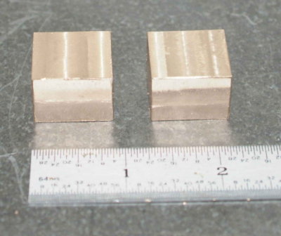
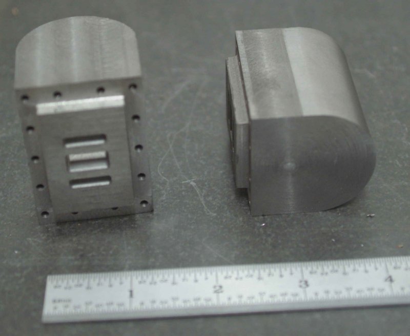
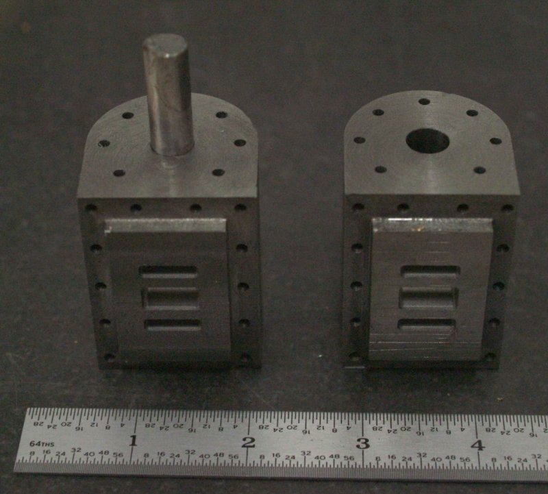
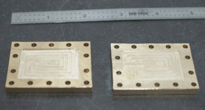
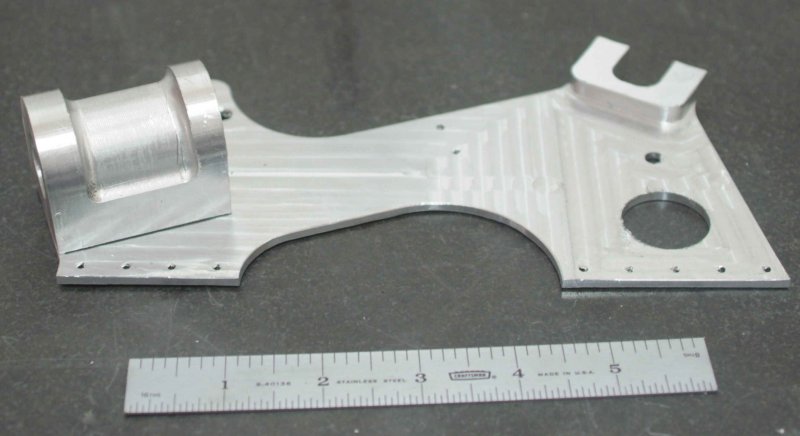
After much blood, sweat, and tears, I finally got two useable parts made on the new CNC mill. There was a pretty steep learning curve, but I feel a lot more confident (before the fall?) about further progress.

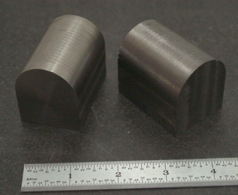
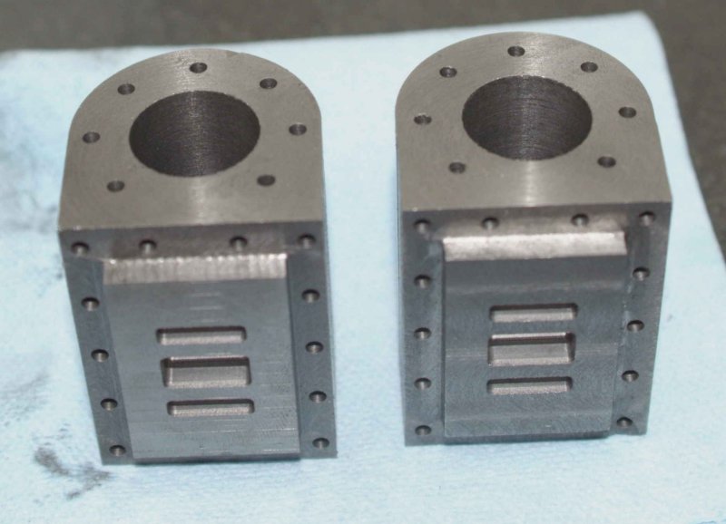
Anyway, here's the two outer frames. No scale items, but they are about 4" tall.

large.jpg


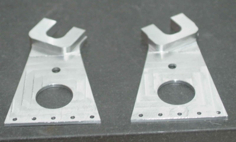
Mill head tram was out for the first one on the left, but the ridges will polish out. :-[

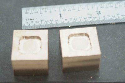
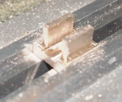
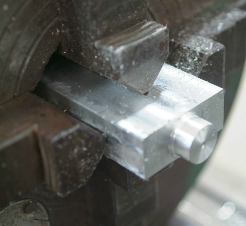
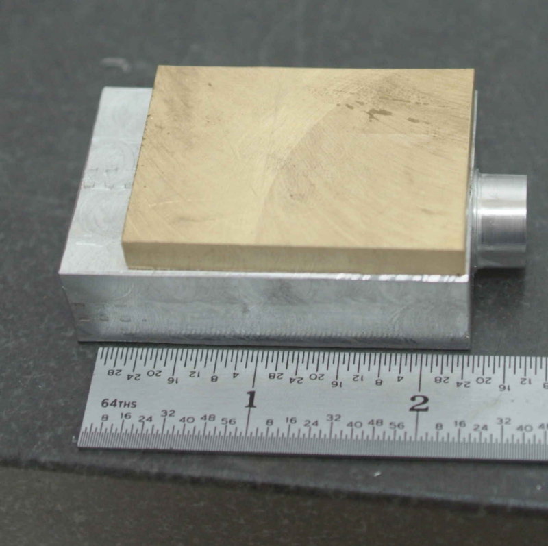
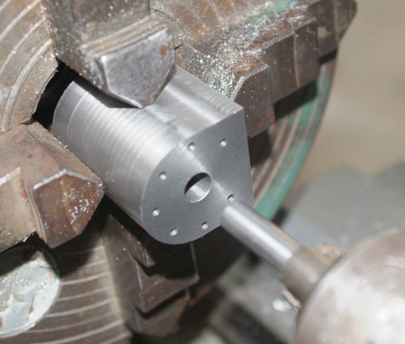
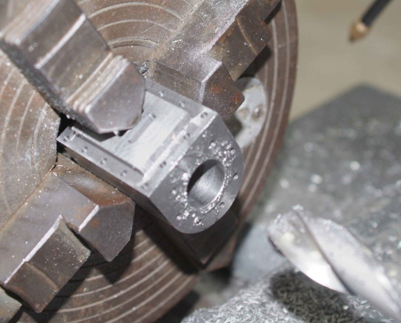
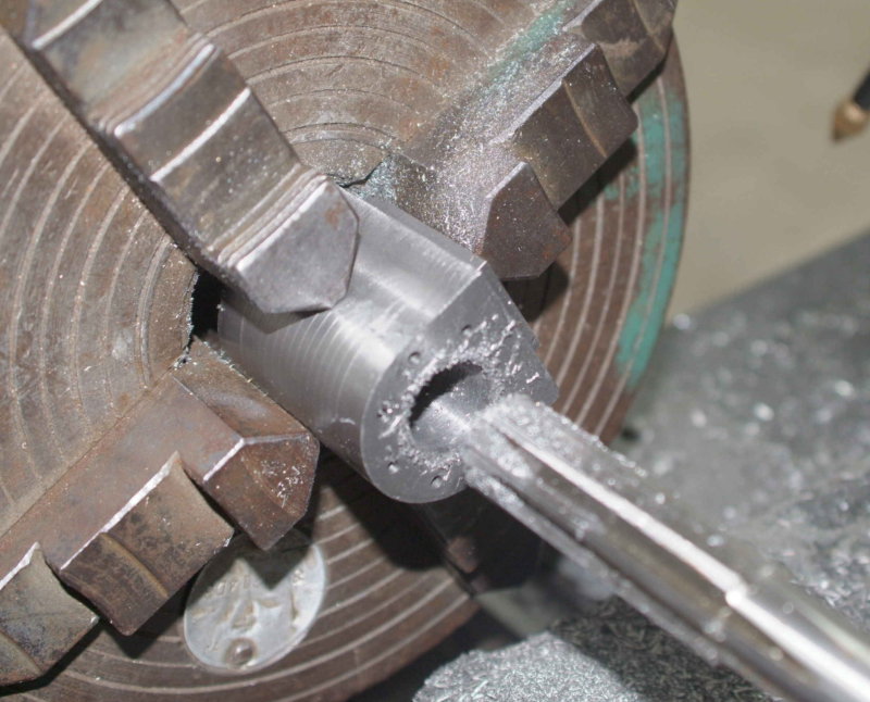
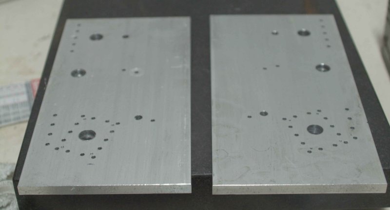
I finally worked out how to hold the small flat parts on a fixture plate. I use some Rhino carpet tape, which holds quite well and is also fairly easy to remove at the end. For these two parts I also used clamps at various stages.
 
kvom I see that you're improving your skill on the CNC machine day by day

you're doing very nice pieces with it, well done :bow:


OT: I can't find any source for cast iron here in Italy :'(
unfortunately it is a very heavy material and shipping costs overseas are high
 
Come on Kvom, mill the ports by hand... if I can do it you can! Seriously, I went very very slowly with a 3mm cutter. It isnt hard just cautious... looks like a good start mate, keep it up.

 
I know I could mill the ports by hand, but the mill will do it too while I blow the chips away. ;D

Drilling the steam passages will be done by hand.

Today I started on the inner frames. I hope not to screw them up as this is all the 5x3/8 material I have. I cut the remainder into 2 10" long pieces, squared away the saw cuts, and flycut one face on each. Then I let the CNC mill drill the many holes in each. The two are mirror images of each other.

large.jpg


Next I need to clean up the fixture plate in order to do the milling. The 1/2" holes in the plates above are just starting points for facing and pocketing operations.

 
I machined the first inner frame yesterday. No real problems and the trial cylinder fits nicely into the through slot.

large.jpg


large.jpg


Unfortunately I didn't have as much luck today on the second. The work raised up from the fixture plate cutting the outline and unfortunately the endmill was in a critical areal where I couldn't save it. :( 
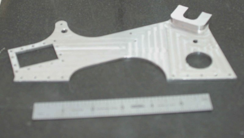
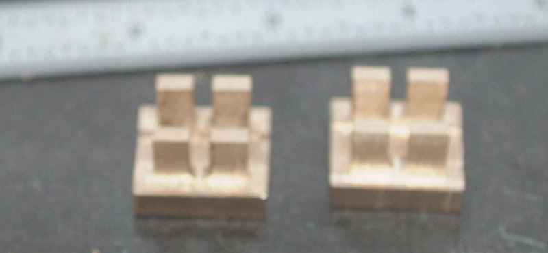
This will have to wait as I have no more suitable aluminum stock.

Guess I'll just work on finishing the CI cylinders next.
 
Nice stuff kvom.
The inner frame is all one piece?
And boy it sure looks complicated to me. It'll take me a while to have the confidence to that.
 
The outer shape is not all that critical; I think Westbury just picked something that looked good to him. The important items are:

1) Centerline of the cylinder needs to line up with the center of the hornblock. That line is tilted 20 degrees from horizontal. The length of the line is fairly critical as it determines the lengths of the piston rod and conrod.

2) The two 1/4" holes are use for the staybolts, which mate the 4 frames together. The smaller hole above the left staybolt hole is for the weighshaft, which holds the reversing lever.

3) The u-shaped hornblocks hold the crankshaft bearings. The centers of the bearings need to be precisely aligned.

4) The two small holes in the middle of the centerline are for mounting a bracket that secures one end of the crosshead guides. Thye bracket needs to be positioned accurately to prevent binding.

5) The mounting holes around the cylinder opening are clearance for studs that connect the cylinder, steam chest, and steam chest cover. All three are thereby clamped to the frame.

In the original the frame was made of steel plate and the hornblocks were riverted on. Later one could buy a casting with the plate and hornblock integrated.
 
Nice work. I like how you've profiled the frames and cylinder block. I too tend to make parts out of aluminum to try out new techniques. It usually pays off. Keep up the good work. That engine is going to be a beauty!

Cheers,
Phil
 
Today I decided to skip any CNC work and actually turn the cranks for a change. I decided to make the valve slides as I had some suitable material. It is a lump of the mystery brass I used previous in Bogs' engine. It's a lot harder than 360 and needs smaller cuts too.

So the first task was to square two blocks and then reduce to size: 7/8 x 13/16 x 5/8.

medium.jpg


Next I machined out the 1/16" deep valve pocket, which is 5/8" square. I used a centercutting .25" endmill to plunge to depth in the center, then moved along the perimeter.

medium.jpg


Next I cut the 3/8" slot. As I broke my last remaining 3/8" endmill I used a 5/16 to cut to depth, then widened it with the side flutes. Then with the same endmill I made the cheek cuts.

medium.jpg


Last is the 1/8" slot to hold the eccentric rod. I used a 1/8" endmill to cut to depth, then a ball-endmill to round the bottom of the slot.

large.jpg
 
Having decided to make the steam chests from 6061 because of material availability, I started on the first one by squaring a suitable block and milling it oversize in all 3 dimensions. Then I center drilled both ends to hopefully end up with a straight line for the valve rod. Next I chucked in the 4-jaw and used a live center in the tailstock to align the block with the center holes. It was not really necessary to be extra precise as I will be drilling and reaming the holes on the mill later. The objective here is just to turn the round boss that will later hold the packing gland. The face of the boss will serve as the datum for further machining.

large.jpg


Here's the blank ready for milling, along with the blank cover plate that will also be milled to fit.

large.jpg


The mill has some issues with the limit switches, so I'm waiting for the vendor to come up with a fix. So using the manual mill and lathe in the interim. The block of aluminum I have for the other chest is a bit bigger, so I decided to put it off for another afternoon.
 
I had a nice visit with Ed T, whom is a forum member and happens to live a few miles from me. He kindly donated a piece of aluminum from which I can hopefully remake the other inner frame. Ed's about to start building a new shop. I visited his current basement shop, and he has a nice lot of gear. Hopefully he'll give us a build thread.
 
I worked on the cylinders the past two afternoon; after fubaring one I had to restart that one with a new atrategy. I used the manual mill to reduce the round bar to size on 5 sides, then milled the round top on the CNC mill. It was slow going squaring the sides as CI needs slow SFM (400 rpm, 5/8 endmill), slow feed (4 IPM), and a modest DOC (.100 shook the mill a little too much for comfort, but .075 seemed OK). Here's the result of those ops:

large.jpg


Then I did the bases. I'd already run the CNC program with the aluminum trial cylinder, so this part went smoothly:

large.jpg


The holes were drilled .101 to be tapped for 5-40 studs. The next job will be to drill the bore and the cover mounting holes (also 5-40).
 
Some more work on the cylinders after watching the Masters golf:

First I used the CNC mill to center drill all the holes in one face each cylinder, then a #38 drikll 1/4" deep for the cover mounting studs. Next I moved to the manual mill to drill the bore 11/32 and then ream .376". I preferred to drill manually for feel. The bore holes now had a sliding fit with a piece of 3/8" drill rod.

large.jpg


Now I used the drill rod in the lathe tailstock to position the cylinder body in the 4-jaw chuck:

large.jpg


Then I used a 23/32" drill with a MT2 shank that I borrowed from school to drill the bore. 400 RPM and a slow hand feed with frequent pecking.

large.jpg


Then reaming to 3/4" with the reamer held in a chuck in the tailstock:

large.jpg


Now they're ready to drill the steam input and exhaust holes.

large.jpg


The plans show 6 studs for the cover plates, but as drawn the two bottom holes interfere with mounting holes in the base. So I went with an 8-hole pattern omitting the bottom hole, which would interfere with the steam inlets.
 
Good progress, Kvom. Thanks for the pics and writing.

Dean
 
Nice job on the bores, kvom. Very clean work with reamer, I usually get a little chatter at the entry.
 
Spent a few hours more working on the cylinders this afternoon. This time it was drilling the inlet and exhaust holes. The inlet holes on each side are drilled from the lower "lip" of the borem on each side to intersect with the pockets milled in the base. Westbury thankfully drew the plans so that the angle of the inlet holes is 30 degrees relative to the bore. This means that the cylinder can be positioned in the milling vise with a simple 30-60-90 angle bar.

large.jpg


I first needed to mill a flat at the bottom of the bore, then center drill the three holes separated by 3/32". Then a 3/32" drill for the inlet holes. Repeat on each end of each cylinder.

large.jpg


The exhaust hole connects one side of each cylinder to the central pocket, and once again a 30-60-90 angle bar serves to set the cylinder in the vise. the exhaust passage is 3/8" diameter, and intersects with one of the stud holes. However, there is enough material left to thread for a stud.

large.jpg
 
I know I haven't been saying much...but I've been reading your thread all along and find it pretty interesting. I enjoy the detail and tips.

Those cylinders are pretty amazing.
 
To those who responded or are following along, than ks for the support. I'm going to need it.

My back is sore from bouncing around in a friend's Jeep this weekend, so I'm limiting the amount of time standing up in the shop in front of the machinery until it calms down. Today I went for a fairly simple part, the steam chest covers, for which I had already sized up stock blanks previously.

The CNC mill had 4 operations: spot drill the mounting holes, drill them, mill a 1/32" pocket on one side with a 3/16" endmill, and then finish the pocket with a 1/16" endmill to get the corners as close to square as possible.

large.jpg


The holes are drilled with a #30 bit to clear the 5-40 studs that will connect the cylinders, steam chest, and cover.
 
Really nice photo documentation going on in this build. :bow: The cylinders look really good. Did they start out as rectangles that were rounded on one end?

Cheers,
Phil

Oops! I double checked on back posts - I see they began as round stock. Not being a CNC thinker I couldn't imagine doing that operation by manual methods.
 

Latest posts

Back
Top