ET Westbury Side Paddle Engine

Home Model Engine Machinist Forum

Help Support Home Model Engine Machinist Forum:

This site may earn a commission from merchant affiliate links, including eBay, Amazon, and others.
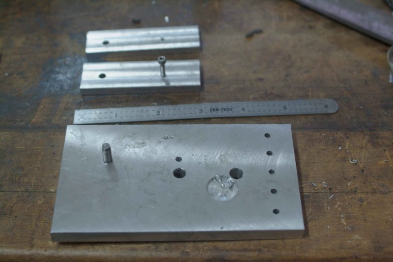
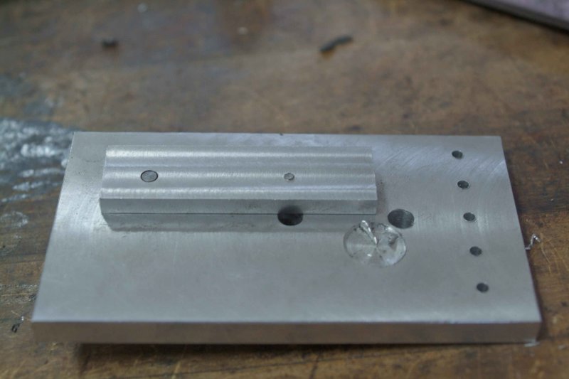
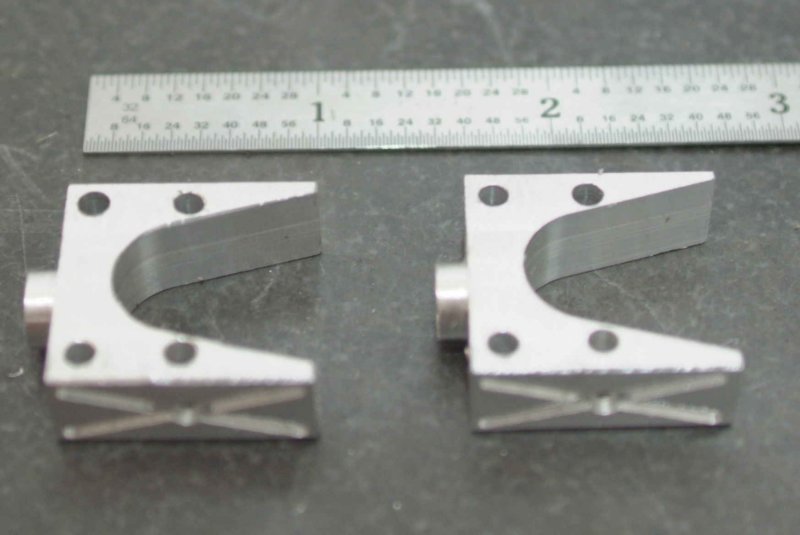
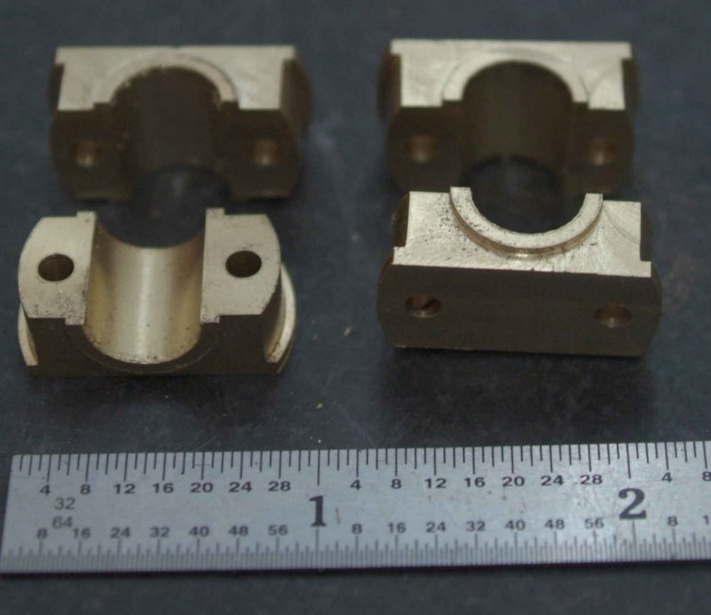
Without CNC, you could mill the top semi-circle with a rotary table.

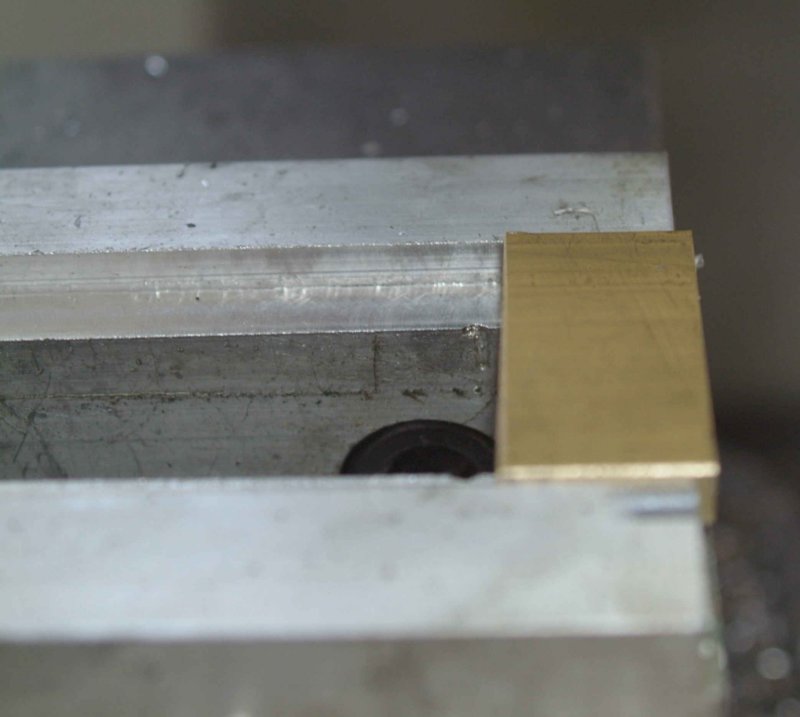
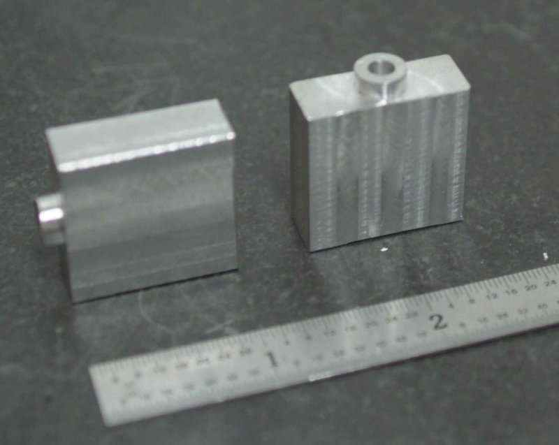
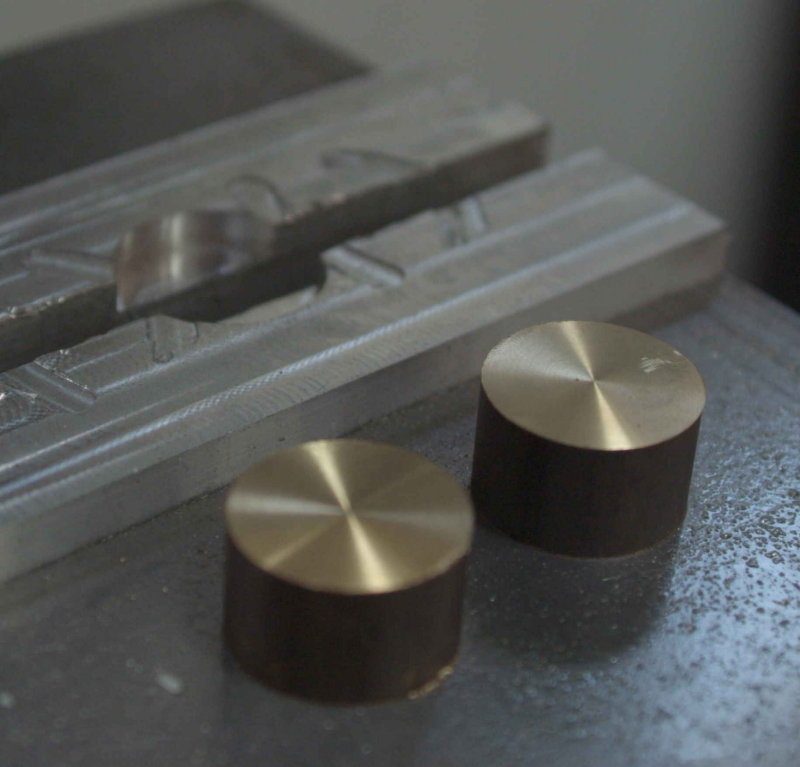
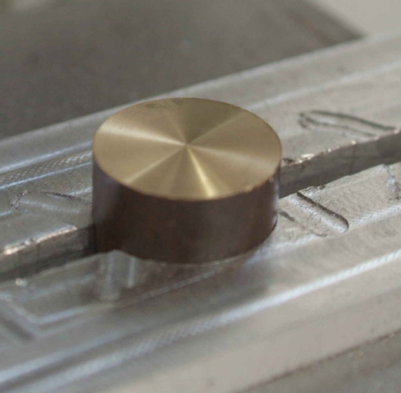
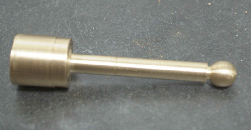
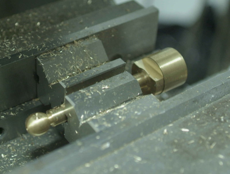
I started with round stock as that was the only suitable form that Speedy Metals offered in cast iron. I had to use 3" of raw stock for each so that I would have enough material to clamp in the vise while milling the round top. All in all probably 60% of the material is now chips.

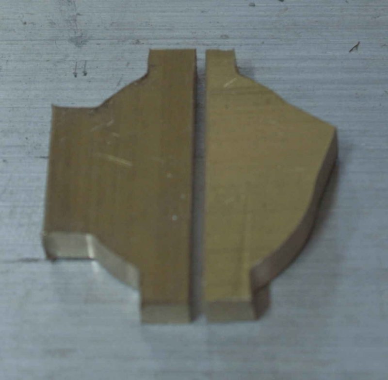
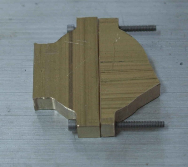
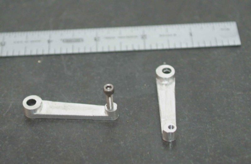
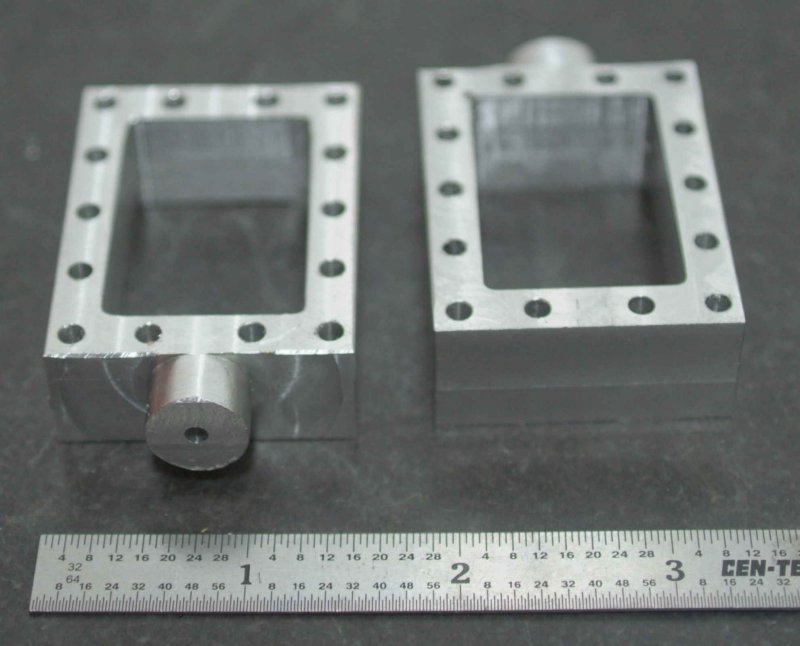
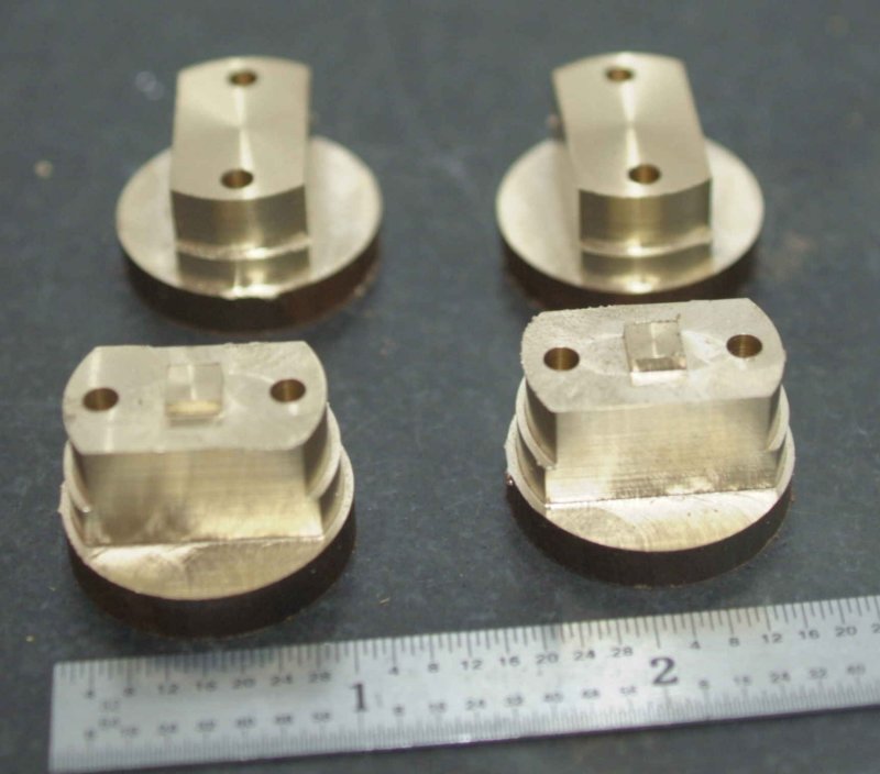
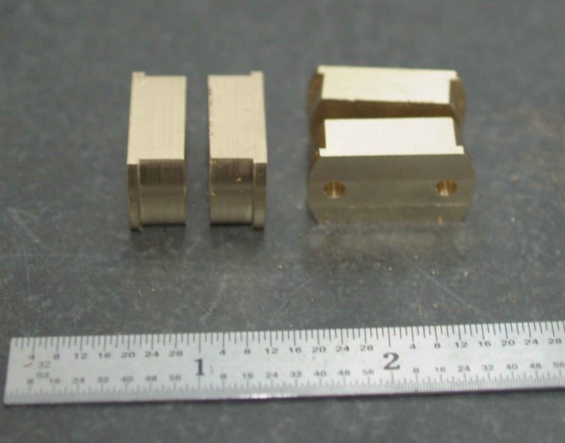
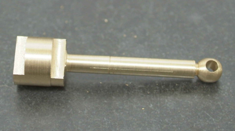
I discovered that the square boss on the base is too large to fit through the cutout in the frame piece. Both dimension are two large by about .01" or so. It appears that while I was using a nominal 5/8" cutter and used .625" in the CAM program, the actual cutter diameter is .620". I should have measured while the cylinder was still in the vise; then it would be simple to just adjust the cutter diameter and rerun the g-code. I can still do that but I'll still have to do all the measurements to establish the zeros in all 3 coords.

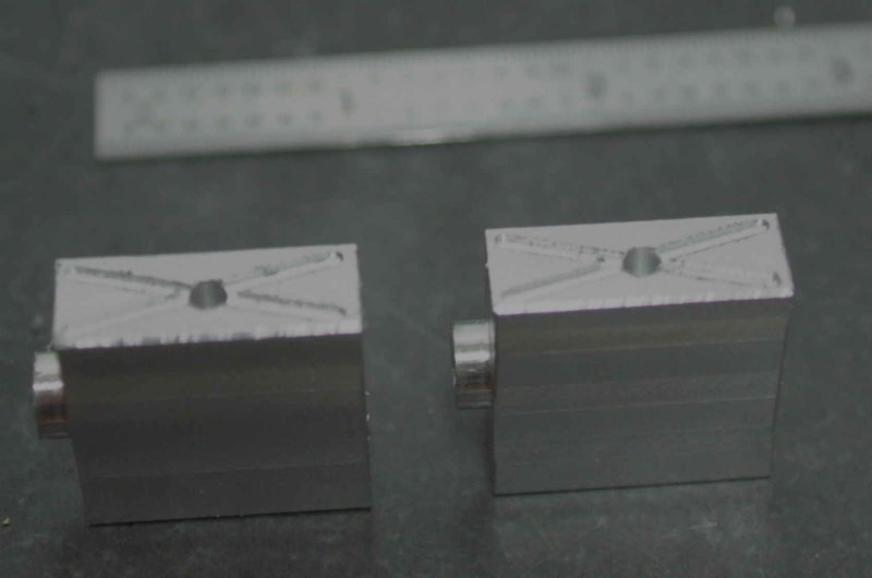
For straightforward milling ops on one-off pieces you don't gain any time with CNC. In fact, it usually takes longer as you have to draw the part, then import it to CAM. However, for any curved surface it's a lot easier. But it's also a lot easier to break endmills if you make a mistake.
 
With my back still a bit sore, I spent yesterday evening drawing up a few more parts in CAD. I had previously drawn the eccentric strap, and having formulated a plan for the machining process I decided to givem this a shot today. The first task was to mill two pieces of 1/4' thick 360 brass to size, 1.5"x.75".

The first step is milling the profiles on both pieces. Since there is only .25" of the .75" width left chucked in the vise afterwards, I decided to put softjaws in the vise and milled a slot to clamp the pieces:

large.jpg


The first pass on the profiles was done with a 1/2" endmill to remove the majority of the material, followed by a 1/8" endmill for a finishing pass. Here's the result:

large.jpg


Next clearance holes for 2-56 screws were drilled manually.

large.jpg


Here progress had to stop as I have no 2-56 nuts to clamp the two pieces together for future milling. Once I obtain the nuts, I will use them to clamp the two pieces securely together, then face mill both sides flat to a final thickness of 3/16", and then bore the central 1" hole for the eccentric. After that it remains to drill the oil hole on the right side piece and drill/tap holes for mounting the eccentric rod on the left.

In the meantime I'll try to locate some more brass for the second strap.
 
Today's parts are the "weigh shaft arms", which form part of the reversing linkage. They are a press fit on the weight shaft and are connected to the lifting links via a screw. So the first order of business was to make a fixture plate with a piece of 3/16" drill rod and a clearance hole for a 5-40 screw. The holes are 1.5" apart. The larger hole was drilled 1/64 small and then reamed .001 under for a press fit.

The blank stock was milled square. Then the 3/16 hole was drilled and reamed to match the fixture, and the smaller hole was tapped 5-40 on the tapping stand:

large.jpg


Next the blank was pressed onto the drill rod, and the other end attached from the bottom with a 5-40 SHCS. The piece was thus held down to the fixture plate securely.

large.jpg


The fixture and stock were all prepared on the manual mill, but now the fixture plate wasm mounted on the CNC mill to mill the final form.

large.jpg


The first one on the right came out "off center". It would still be useable since the holes are correctly spaced, but I'll plan to make another one later. I have no idea why there is a discrepancy in setting the zero. For the second one I eyeballed a .003 correction in the Y direction.

Since all the milling was done with a 1/4" 2-flute endmill, no tool changes were needed, so the milling takes only a couple of minutes at most. The prep and setup tool a couple of hours.
 
kvom said:
Since all the milling was done with a 1/4" 2-flute endmill, no tool changes were needed, so the milling takes only a couple of minutes at most. The prep and setup tool a couple of hours.

So, just like manual milling, except both steps take a couple of hours, right?
; )

Thanks for the progress update, Kvom!

Dean
 
Fantastic stuff Kvom, Im envious of the pace of your build. :bow:

While I used the same plan set to get inspiration Ive deviated dramatically from Mr Westburys engine. This means Ive got to design and make a component, prove it works, THEN go and make its mate.

Its been slow progress and work has had me away fairly often over the last few months (this isnt going to let up at all it seems) so opportunities seem limited. I went into the shop last night to finsh the cross heads and ended up just cleaning things... another moment wasted.

I enjoy your posts and it helps keep me motivated. Keep it up mate.

Cheers

Rob
 
Today I made a start on the crossheads. I decided to make these from 6061 Al rather than brass as I had the right size material. So the guide bars will be brass to provide a good sliding surface. The crosshead requires machining on three sides, so this is the left side where the piston rod attaches. Material is 1x1x3/8" with 1/8" spigot. CNC milled the spigot and drilled to tap for 10-32 thread.

large.jpg


Once again the CAD/CAM work takes the most time, then sizing the stock on the manual mill. The actual spindle time on the CNC mill is less than a minute, as most of the time is setting the zeros, changing tools, etc.
 
Spent a little bit of time after dinner in the shop to machine the top side of the crossheads. Here there are two crossed oil grooves 1/16" wide by 1/32" deep, plus a 1/8" oil hole (which presumably allows oil to reach the conrod link pin). As usual, programming and setup take all the time, and the machining is rapid.

large.jpg
 
Kvom
That engine is going to be a showpiece when you get her finished. Beautiful work!!

Steve
 
I finished the 3rd machining operation on the crossheads this morning. Drill 4 #30 holes for mounting the side plates and then mill then space for the conrod to swivel vertically.

large.jpg
 
Looks good kvom. This is a really interesting build.

Cheers,
Phil
 
Today's contribution is fabrication of the expansion links, wich form part of the reversing mechanism, one link per cylinder. A link is connected to 4 other parts.

1) The circular slot is connected to the end of the valve rod, which slides along the slot;

2) The center hole is connected to a lifting link that is in turn connected to a weigh shaft arm.

3) The two outer holes are connected to two eccentrics.

In operation, the weigh shaft is turned causing the lifting link to raise or lower. This in turn rotates the expansion link which reverses the timing of the eccentrics, thus reversing the engine's rotation.

These parts are seemingly ones where CNC gains the most in terms of effort. To make manually would require a lot of filing to achieve the contours, as well as the rotab to make the slot accurately. Once the CAD/CAM was complete, each part took less than an hour to machine, mainly because of numerous tool changes.

large.jpg


The part on the right shows where material was left on each end after CNC work; this was necessary to keep the work secured in the milling vise. I programmed a shallow radial cut to indicate the final contour. The ends were then finished on the manual mill using this cut as a guide for positioning the piece in the vise.

 
Hi Kvom,
Those links look really good, you are providing good inspiration to master the CNC learning curve.

Dan
 
These look great Kvom, Im not overly happy with the drilled corners and am using a triangular file to make mine square without the drill holes. I am ussuming that you wont be running the engine for long periods at a time (ala at shows etc)?

Edar T. (Westbury) was concerned about wear in these units and suggested that they would be better built from hardened steel or hardened after manufacture if warpage could be eliminated. His are from 3/16 mild steel and I see no problem with brass of the thickness you have used for short term useage.

"The material specified for the link
is mild steel, which has been found
quite satisfactory, and shows no
signs of wear so far, but it would be
better still if made in a harder material
such as carbon steel, which, however,
has not been readily obtainable in
3/16 in. thickness. Case-hardening the
mild steel links would give everlasting
wear, but risk of distortion is very
great in a component of this shape."

Im still undecided yet and it was interesting to see that we are up to this component together. I am inclined to go the bras route..., can always remake later if it becomes a problem.

Keep it up...watching with interest..
Rob
 
Artie, I doubt the engine will see a lot of hours, anjd as you say the part can be remade. Or the slide block could be remade.

I am making parts in a "random" order as the spirit guides me, or as I have material or tools to do do. Today I decided to work on the steam chests some more. First I drilled and pocketed the one I started some time ago, and then started on the second one. This time I milled the circular spigot rather than turning on the late.

large.jpg


I still have drilling and tapping to do on both, and the first one is a bit thicker than in the drawing.
 
My next effort is the "big ends", or crankhead bearing as Westbury termed it. Starting material is some 1" diameter brass rod. On the lathe I faced, then parted off 4 pieces about .7" long, and then milled the parted side flat. To hold the pieces repeatably and securely in the CNC milling vise, I milled a 1" diameter pocket .2" deep in the aluminum soft jaws:

large.jpg


large.jpg


Then the side profile could be milled as well as the mounting holes. Once removed from the vise, the round holding stub was milled from the bottom and each piece brought to size (5/16").

large.jpg


large.jpg


The 5-40 threaded rod I will use to connect the bearing halves and the conrod measured .118", so I drilled the holes with a #31 (.120) for a close fit.

Finally the pairs were clamped in the milling vise to finish the sides. After milling the round boss, the crank hole was creaedm by drilling 11/64" and then reaming .376 for a sliding fit on the 3/8" crank.

large.jpg


These little parts took the best part of two afternoons in the shop, not counting CAD/CAM time.
 
Yes but you've got some great looking little parts!

-Trout
 
I am in awe at the quality and speed of your work Kvom,and find it facinating to see this engine made using CNC.My brother with whom I made this engine years ago thinks it is easy and "not real model engineering" with cnc but having done a little bit know otherwise,there are a load of new skills involved.We must forgive my brother,he is the old school at 84 so go easy on him.
Don
 
Thanks for everyone's comments.

Don, your brother will like the current effort better. No CNC work at all as I try to make a conrod to ET's plan.

Rather than steel, this is some 1" diameter brass rod, of which I have 7' and thus enough to screw up many times. Mounted in the lathe, I turned the following piece:

large.jpg


Not having a ball turner, I used Marv Klotz's ball turning program to output a schedule for turning a 1/2" diameter ball using 5 degree angle increments. The shaft was turned to 3/8" with the neck nearest the ball grooved to 1/4". From the end of the ball to the end of the shaft is 3.25".

Next the piece was mounted in the Bridgeport vise held between two V-blocks. A 1/4" endmill was used to make a flat on the side of the ball plus cut a flat that will be the finar form of that end of the rod. The ball was then center drilled, drilled, and reamed to 1/4" diameter.

large.jpg


A second flat was milled on the large end to provide a reference for clamping to bill the large end on the opposite side.

large.jpg


The next operation will be to put it back in the lathe and use the taper attachment to taper the shaft from 3/8 to 1/4 over its length.
 
Thats an interesting use of the v-blocks,I'll have to remember that.
Don
 

Latest posts

Back
Top