ET Westbury Side Paddle Engine

Home Model Engine Machinist Forum

Help Support Home Model Engine Machinist Forum:

This site may earn a commission from merchant affiliate links, including eBay, Amazon, and others.
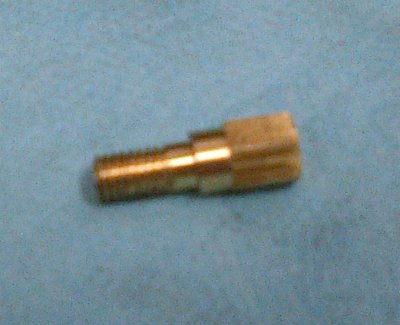
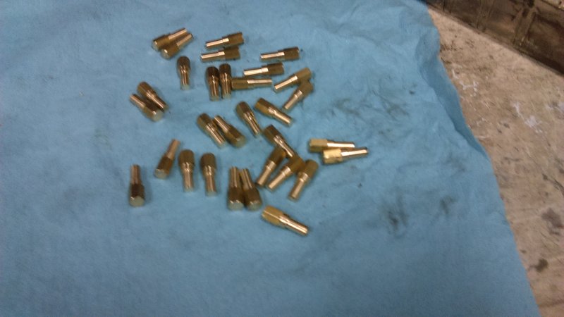
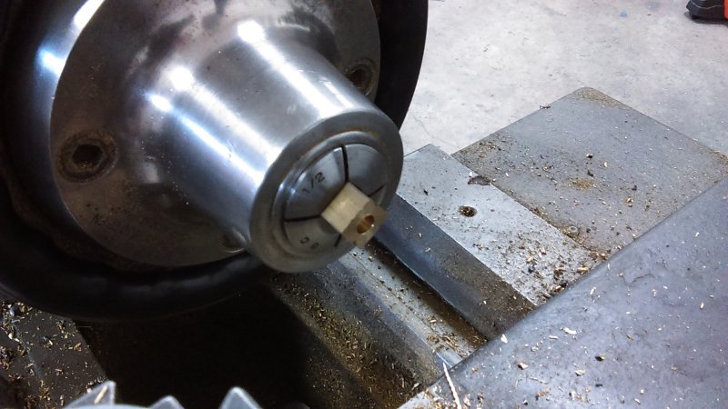
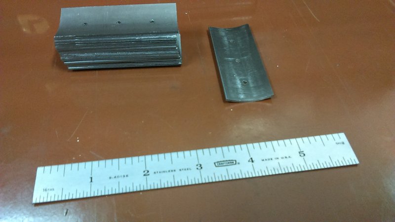
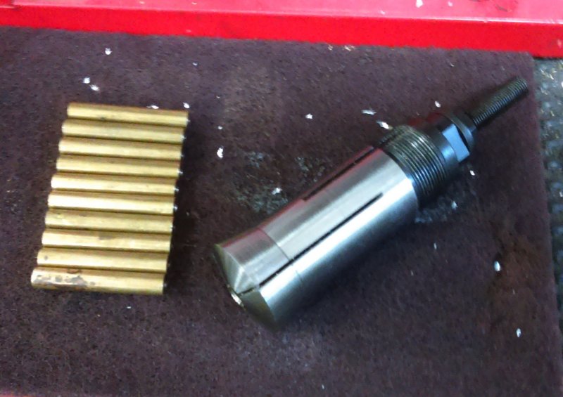
Today I needed to make 16 tie rods for the paddle wheels. First good opportunity to use the 5C collet stop I bought some time back. I needed to have all 16 pieces of 5/16" diameter brass rod cut to 1.875" length. Using the collet chuck on the lathe and the parting blade as a stop., I first cut off pieces at around 1.90" long. Next I faced one end of each and spot drilled that face.

Then measured the first piece and faced the other end to the desired length.

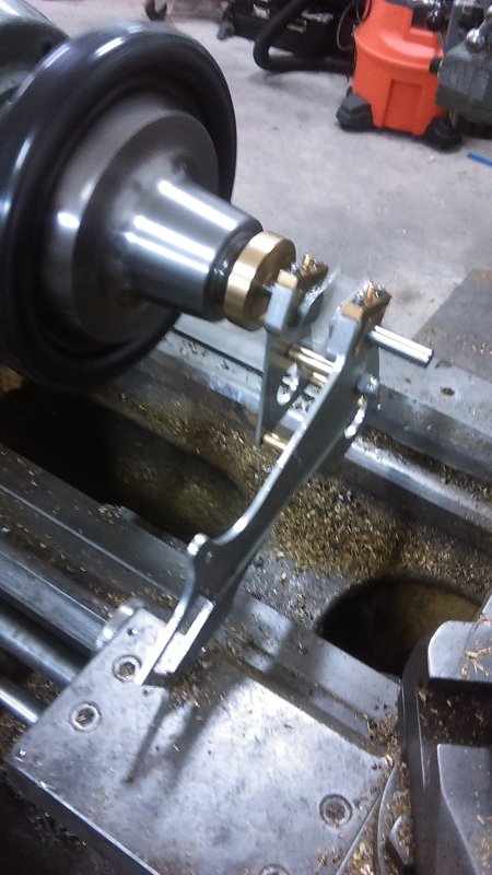
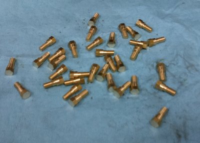
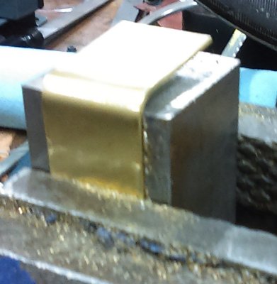
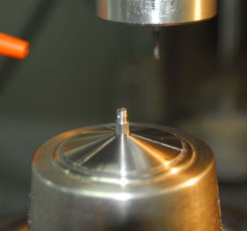
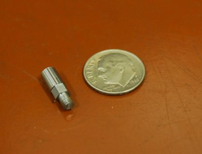
Next, I installed the collet stop and adjusted it so that about 1/2" of brass stuck out from the collet. Installed on the chuck, I carefully set my facing tool to the exposed face and locked the carriage. Now I just needed to insert the faced end of each piece into the collet against the stop, run the face tool across the exposed end, and spot drill it. Result equal lengths within tolerance of a few thou +/-.

large.jpg


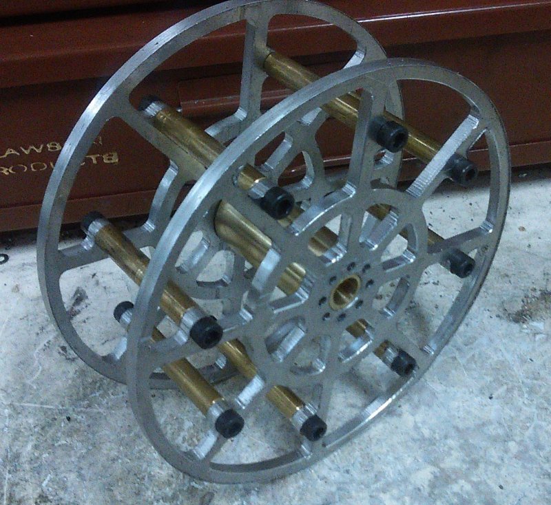
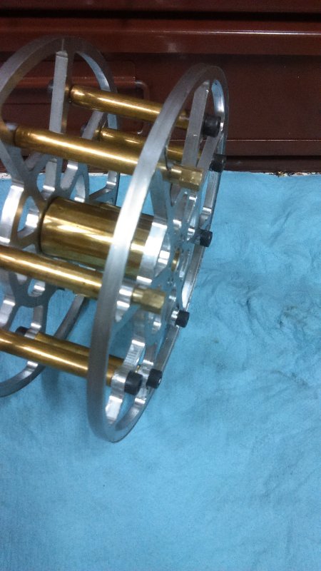
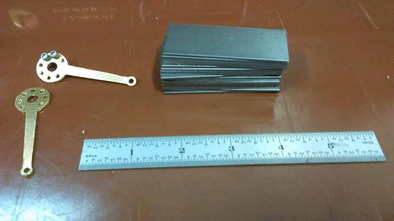
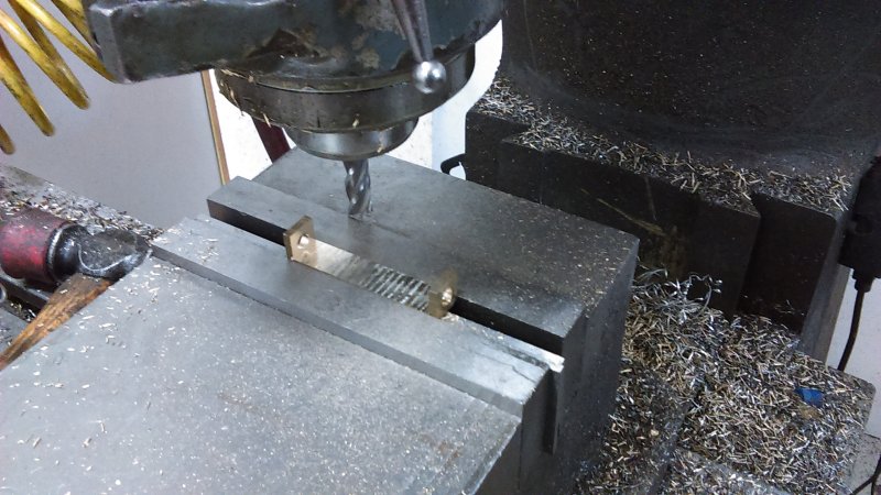
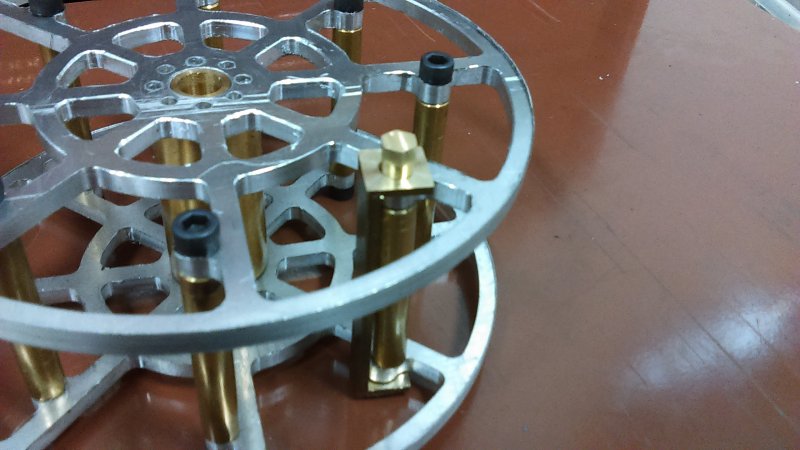
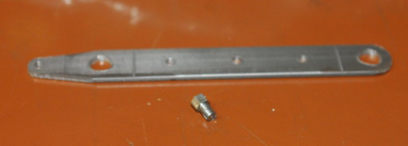
The stop was also useful in drilling both ends for 10-32 tapping. With the pieces in the collet, I could get a constant DOC by locking the tailstock and using its spindle rule as a reference. After tapping each end, I was able to test-assemble two of the frames and the hub.

large.jpg


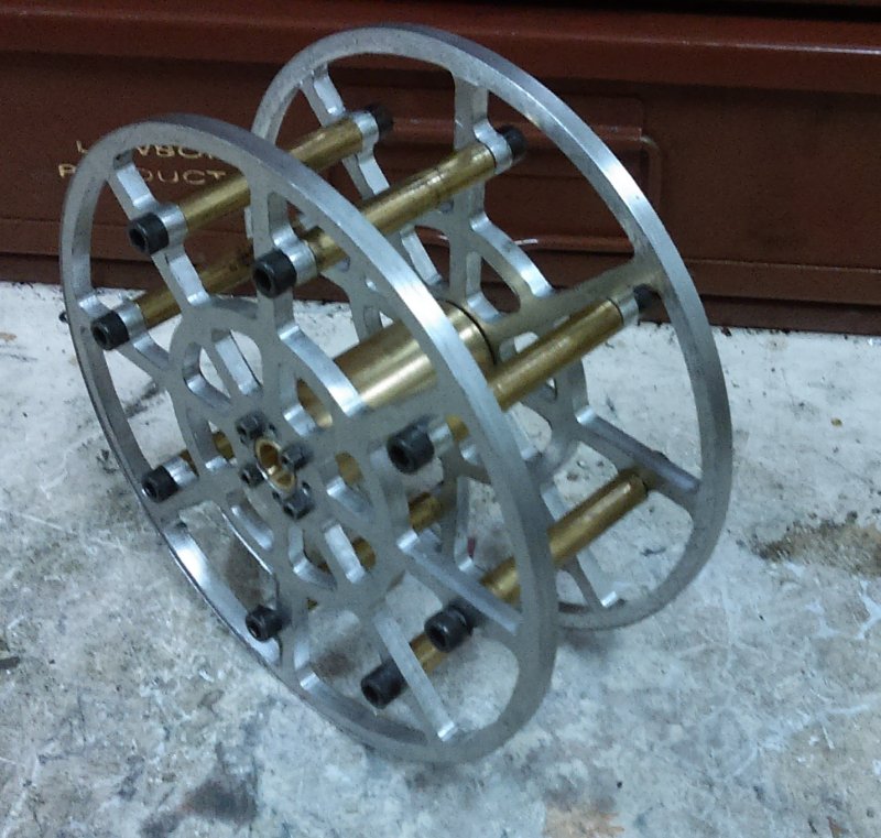
The inner frame is held firmly against the hub boss without screws, so I'm thinking drilling for them won't be needed.

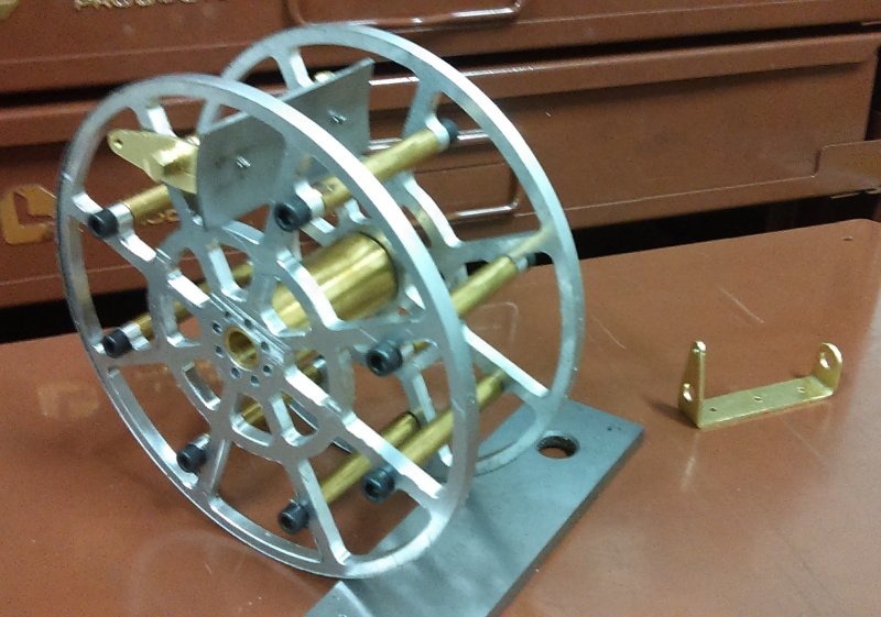
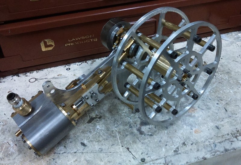
Finally, poser shot on the starboard engine:

large.jpg
 
Those wheels are really nice,makes me wish i had a cnc and the know how to run it.
Don
 
Thanks for looking in.

Having decided to make the paddles I now need crankshafts long enough to support them. First stage in remake is the webs on the CNC mill from some 1/4" HRS.

large.jpg


After cutting free and milling off the tabs, I thinned them to 3/16". Then used Loctite 620 to assemble in two stages.

large.jpg


After curing tonight, I'll cut out the unneeded section on the Bridgeport. The 620 should be plenty strong for this application, but I'll pin the side shafts anyway.
 
Will you be brazing it together or just rely on the 620 glue and pins?
 
No brazing for me. The drill rod is straight enough, and all the holes were reamed .376. There's not enough torque from this engine to budge the shafts.

That's all I did on the Joy engine, which has a lot more power.
 
With a bit of shop time today I wanted to finish the crankshafts. I decided to use a pair of 3-56 screws as pins for each; first because I couldn't find any roll pins in the shoop, and second because I can still disassemble them if for some reason I need to redo something. Later on I can mill off the heads.

large.jpg


Second task was to machine a pair of dies to apply camber to the floats. Did the machining on the CNC mill, and tried them out on a piece of the 1-1/16x1/16" CRS I ordered from McMaster. It seems to form very well using the vise on the Bridgeport.

large.jpg


I now need to drill and mount some guide pins in the die to ensure that the floats are kept straight while being cambered. The pins need to match holes drilled in the floats for attaching the lever arms. I'm leaning towards using drive screws to attach the levers, so the hole sizes will depend on which size drive screw, probably #4.
 
Start reassembly of the port engine with the new crankshaft. Ran it for 30 minutes on the lathe to loosen it up.

large.jpg


While that was running, more fettling with the cylinder/crosshead/guide bars, which are still a bit sticky on one end. My goal is to get the cylinder side motion moving smoothly before attacking the valve side.
 
The paddles require a custom screw that both fastens the frame to the tie rods but also provides a surface for the float brackets to pivot upon. Westbury names these pivot screws. I need 32 of them to replace the 32 10-32 socket screws currently holding the paddles together. I am making them from 1/4" hex brass rod. When making a large number of things its useful to come up with a system for doing the same operations quickly using the same tools and setups. I had devised my system, but decided to only make the first two screws in order to verify the process.

Op1 - part off lengths of the rod at .90" of length on the lathe.

Op2 - face one end of each cutoff

Op3 - using collet stop in the hex collet, face the other end to make both cutoff the same length (.77" in this case).

Op4 - mount collet chuck on the CNC mill and mill two diameters - .24" for the pivot, and.188" for the 10-32 thread.

Op5 - threadmill the 10-32 threads for .375"

Here's the result of the first screw:

medium.jpg


And on the paddle:

large.jpg


With success on the first pair, I started the process of making 32 more (2 extra). This time I combined Op3 and Op4. Got them all done except for the threadmilling, which will have to wait for the next time in the shop,

large.jpg


The extra-long head is needed to hold the work in the collet, but a finishing app will lop it off to 1/16".
 
Looking great. I'll be at that stage around Xmas hopefully :D
 
Got the stock for the floats cut to plan dimensions: 2.625x1.062x.062". Did a couple of extra just in case. After some experimenting, I decided to attach the brackets to the floats with #4 drive screws. The .104" hole for these isn't far off from the 3/32" rivet size ET used, and the head size looks similar.

Rather than bending the brackets from metal, I'm thinking of carving them from some 1/2" square brass bar I obtained recently at a bargain price. By using a square 5C collet in the lathe, I can ensure that the pivot holes in either end will line up. The arm will be attached. I'll make a trail piece later this week when I get the collet.

The other task of the day was to extract the master rods from some 1x1/16" brass bar. Drilling and profiling were done on the CNC mill, followed by tapping the holes for the slave rods 4-40 on the tapping stand. 4-40 is quite close to the 6BA size in the plans, and there is space for socket screw heads to be used for trial assembly. The slave rods will be cut in the same way from the same material.

large.jpg
 
Today I had a couple of shop hours to experiment with making a float bracket from some 1/2" square brass bar. I was able to borrow a 5C collet from a friend. After cutting a piece and facing to length, I drilled a 1/4" hole in each end.

large.jpg


Then over to the mill to convert most of the piece to chips.

large.jpg


A trial fit revealed a problem. The bracket interferes with the tie rod!

large.jpg


I had used some 5/16" rod for the tie rods, while ET's were 3/16 at the ends necked down to 1/4" in the center. I can't go back and do that since my pivot screws are 10-32, but I can reduce the ends to 9/32 and the centers to 1/4, since I'll need clearance there for the drive screw heads.

In any case, I'll finish the first of these manually before I program any CNC work for the other 15.
 
Did some experimenting with the bending option. Milled a 1" wide slot .04" deep in a piece of steel and used it as guide for bending some 1/16" thick brass bar. By scribing lines on the stock for aligning on the steel's edge, I can get a good idea of how much to adjust dimensions to account for the bend. It appears to be 1/16" in both length and height. I did the bending by striking with a dead-blow hammer directly, and the bent edge is still fairly straight. I think using a flat piece of aluminum between the brass and the hammer will be even better.

medium.jpg


I'll machine a test piece to validate. Since I can't get two 1/2" brackets from 1" wide stock, I'll wait and order some 1/2" wide brass for the rest. The 1" stock will be used for the slave rods.
 
Success in getting the first trial paddle/float. I made a SWAG about where the bends should be to get a bracket that swings freely on the pivot screws. While machining the part on the CNC mill, I had it scribe two cross lines where the bend would start (i.e., I'd line up the line with the top of the steel block. The first effort came out about 1/16" too narrow for a minimum fit. However, I was able to manually adjust the ends slightly in order to get a drill bit to clear both pivot holes. The second time I moved both lines apart, and this time I was able to mount the bracket on the screws, albeit still slightly tight. For the "real" ones I'll widen the brackets a bit more.

With that done, I proceeded to drill holes for the drive screws in one of the float blanks, and then squeezed it in my little die blocks to impart some curvature. Then hammered in the 3 drive screws. Here's the assembly mounted on a paddle.

large.jpg


The first bracket attempt is shown to the right, On the production floats I'll need to mill off the ends of the drive screws that protrude.

These two were made from 1" wide stock, but I'll wait to obtain some 1/2" before making the rest. In the meantime I still need to make the slave rods as well as 30 smaller pivot screws.
 
Looking really great. Learning heaps on this thread.
 
Not much shop time this weekend, but did manage to drill and camber the floats:

large.jpg


So now I see a conundrum. Do I want/need to paint the floats? If so, then with brass brackets it could be difficult to paint just the steel portion. If I paint the floats before attaching the brackets, then I still have to mill off the stubs of the screws. That will require a touchup of at least the concave side. For these reasons, I'm going to make a test bracket from the same 1/16" CRS. If the brackets are also steel, I can paint both them and the floats after otherwise finishing the assembly.
 
I've decided to make the brackets from steel and have ordered material from Enco. In the meantime I made a start on the 30 small pivot screws that connect the arms of the feathering assembly to the bracket arms. These will have a 5/32 hex head, an a 3/16 shaft of which 3/32 is threaded 5-40. These screws start off as pieces of 3/16 drill rod which I parted off on the lathe, and then faced to a 0.57" length. This was tedious making 30 of these pieces and a couple of extras. That was done yesterday.

Today, I used the CNC mill to form the shaft and head with an endmill, and the threads with a threadmill.

large.jpg


Each of the operations took a bit over a minute, plus time to remove one piece from the chuck and insert the next. A collet stop ensured that each screw went into the chuck the same depth. As for today, each screw looks like this:

medium.jpg


To finish, each will be chucked thread down and cut down so that the hex head is 1/8" thick.
 
Spent some scattered time over the past week on the engine. With the new crankshaft in the port engine I set the eccentrics to the same angles as the starboard, but it still doesn't run. The starboard engine runs very well, but still has the old crankshaft, so I don't want to disassemble it until the port engine is running. Other than that, I finished the 30 small pivot screws plus 14 of 16 pivot brackets in steel (ran out of material). I have some left over sheet from the floats, and I should be able to make two more brackets from it.

large.jpg


The scribe lines are where the brackets will be bent.

Now I just need to make the 14 articulated rods and the engine fabrication is done except for a base and some sort of reversing setup on the weigh shaft.
 
Back
Top