ET Westbury Side Paddle Engine

Home Model Engine Machinist Forum

Help Support Home Model Engine Machinist Forum:

This site may earn a commission from merchant affiliate links, including eBay, Amazon, and others.
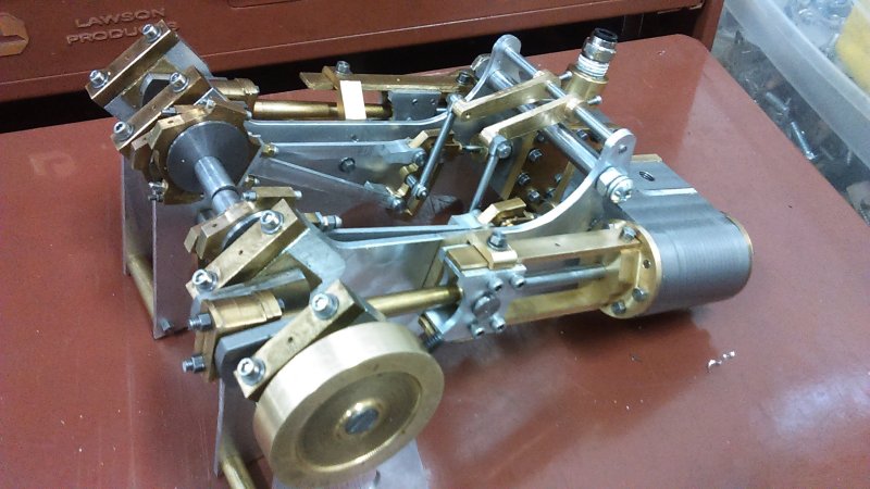
I have a semi-runner, at least forward. I left the eccentrics the way I had them yesterday, and took some time to try to make the steam chest more air tight. One thing was to tap all of the cylinder's mounting holes with a bottoming tap, allowing be to get a tight fit with all but two of the 14 screws that hold the cylinder/frame/steam chest/cover together. I also adjusted the center of the valve slightly, and added another staybolt between the inner frames under the cylinder in order to reduce flexing.

Applying air with the weigh shaft set for reverse, I was getting the engine to kick, but not turn over completely. Switching to forward, I had the same thing for a few turns until suddenly it ran for a few seconds. With a bit more are pressure it took off. I'd hope running in will reduce the amount of air needed, currently about 20 psi. Gaskets and packing would help too.

I'll see if I can get a video, although it would probably be taken with a phone and no tripod.
 
It's ALIVE. Well done. I hope to be at that stage in about a week. I have just retapped the cylinder holes with JB weld and a bottoming tap. This fine grain cast iron is a pig to hold a thread.
 
Herb, I assume you translated the BA threads into some metric ones.

I started a test assembly of the second engine this afternoon. Retapped the cylinder holes, and then enlarged the mounting holes in the frame. When they were drilled initially 5 years back I didn't use the 5-40 clearance drill.

I will have to remake the front cylinder cover as the mounting holes are off. And it appears that I may have drilled the holes in the cylinder a bit off center as well. So I'll have to fit the cover's holes to the cylinder.

I also need to make the eccentrics. I have no 1.25" steel rod remaining, and the only scrap pieces I have that will work are 2" diameter. Guess the lathe will get a workout.
 
Yes, you're right Kvom. I translated 6BA TO 3mm. Thread pitch is slightly finer at about 51 tpi as compared to around 48 with BA. Bottoming the thread seems to be doing the trick.
Good luck with the second engine.
 
I used 5-40 for all the frame and cylinder screws, and 4-40 for the pivot pins. A few others here and there as needed.
 
Two longish days in the shop has gotten the port-side engine assembled. A good part of yesterday was spent turning the eccentrics, and today I spent a good while shortening screws for both sides. Here's the state at the end of the day:

large.jpg


I used the starboard side as my example for setting the eccentrics, given that it would be embarrassing to have the forward setting turn in opposite directions. I COULD have tried putting air to it today, but I figured if it didn't run I'd either have to take it all apart to investigate or else be depressed for a couple of days since I won't be in the shop tomorrow.

The inboard ends of the cranks are not very well aligned, and I hope it's mainly a matter of the staybolts not being precisely fitted. Obviously for the engine to be self-starting the cranks need to be coupled at 90 degrees to one another. I may try aligning them with a tube and then adjusting the staybolts to match.
 
I used the CNC mill to cut out a pair of gaskets from .01" thick Teflon sheet, as shown here. Holding that stuff down flat is not so easy, and I came up with the system shown here. For further gaskets I want to skim the plate flat with a face mill in order to get consistent hole sizes. Tool is a 80-degree engraving bit with a .03" flat on the tip.

large.jpg


After I installed these on the port side engine, I got it to run, but still not self starting and needed 30 PSI. I couldn't detect any air leakage around the steam chest with the gaskets.
 
Coming along really well there K.

You might know that for 40 years I was involved with making model boats, and one of my dreams was to make this engine and floats (paddles) and mount them into a hull, but never achieved it as real life got in the way.

I might be wrong, but I think this engine was designed by ETW to go into a hull of the 'Director class ship', 'Dexterous, Director, Faithful, Favourite, Forceful, Grinder, Griper' all built in 1957/8. A diesel/electric (not steam) ship designed for manoeuvring aircraft carriers about, as it was not only powerful, but could easily turn in it's own length and because of the paddles, had huge stopping power, which normal tugs of that time didn't have.

Are you going to be making the feathering wheels to go with the engine?

paddles_zpsag7hs9kt.png


John
 
In the article Westbury names the boat "Devonia" as the target for the engine. He also names the engine itself "Neptune".

Given the architecture, this engine could be used in many boats since the width is easily customizable by varying the lengths of the staybolts and weigh shaft.

I'm still thinking about the paddles
 
Spent some lathe time making a coupler from a chunk of steel round I had in the bin. This is very similar to what was done on the original to add temporary rotational mass prior to mounting the paddles.

large.jpg


Even with this added the combined engine wouldn't run on one cylinder, and it still is a bit stiff when turned by hand, I also found air leaking around the cylinder/frame interface, so cut another pair of teflon gaskets. I should get the tubing I need to connect both engines to air this week, and perhaps will have better luck getting it to run.

In the meantime, started rereading the chapters on the paddles.

I've found that the tiny 4-40 nuts on the the pivot pins tended to work loose when the engines did run briefly individually. Since I used them to connect the eccentric rods to the expansion link with the nuts on the frame side, they're very hard to get back on. So after the next disassembly I'll reverse the pins so that the nuts are on the outside, eventually with a bit of thread locker.
 
I stand corrected K, not having all the info with my plans, maybe the 'Director Class' took my fancy at the time for this engine.

You really need to get your engines smoothed out, as in real life, the paddles would be running between 100 and 150rpm max.
The feathering ones would be ideal to try out your CNC machine. I actually cut the four main frames by hand, out of ali, but were given away years ago to a mate who said he could use them.

But my hankering is still there, even though I could never handle a model boat of that size any more.

John
 
As that other John said. " life is what happens to you when you're busy making other plans" :D
 
Last two session in the shop were devoted to starting the paddle wheels: the 4 frames. Here's the progress on the first 2 with the CNC work complete. Diameter of the frame is 5.75".

large.jpg


This aluminum alloy is quite gummy, so I'm taking very shallow DOC in cutting out the windows. Over 90 minutes for each. Because I'm using 5-40 screws for the hubs, I made the central hole .5" vs 9/16 to give a bit of space for countersinking the screw heads.

I can't imagine cutting these out with a jewelers saw. Rotary table would work though if your hands are steady.

For the engine body, I got my tubing today and so will be able to apply air to both sides together. Not that hopeful, but who knows. In any case I need to do a complete disassembly to finish up a few things. I suspect that using brass for the bearings instead of bronze might have been a bad decision 5 years back.
 
Some progress and some steps back today. For progress I let the CNC mill chug along on the other two paddle frames. These were the longest I had ever let run unattended, and since I use air blast for chip clearance the air compressor running continually made the shop rather noisy.

The mailman delivered 6 small oil cups from PMR, so I tapped the holes (2-56) for these on the bearing caps and top crosshead guide bar. I know the purists would make their own, but at less than $3 each I couldn't justify the time.

Next, started to take apart the starboard engine with an eye towards getting it more air tight as well as looking for friction points. I decided to trash the old forward cylinder cover and gland screw, as I could not get a good fit with packing, That will be a project for next time. I'm also running into the issue that when fitting up one engine by itself, the inner frame flexes enough that getting everything nicely aligned can be a problem. An idea that comes to mind is clamping a stiff steel bar to the inner frame feet to keep them in line.

I ordered from McMaster a length of steel bar 1.25" wide and 1/16" thick that may work for the paddles themselves. The paddles need to be bent into a slight camber, so I'll need to make some press dies. Without knowing how springy the material is, the camber of the die may take some experimentation.
 
Are you going to build a boat for the engine ??
 
Spent a good part of the afternoon remaking the forward cylinder cover for the starboard engine as well as two gland screws. Threads for the glands are 1/2-20, vs. the 1/2-26 Westbury calls out. The cover started out as a cutoff from a nominal 1.5" hex bar, turned down to 1.47". The screws are turned from .75" round bar.

large.jpg


I originally drilled the cylinders for 8 screws on each face, but after finding that the two behind the guide bars couldn't be countersunk and that one would intersect the steam ports, I ended up using only 5 screws for the inner cover and 7 for the outer.
 
After reassembling the starboard engine with 3 gaskets on the cylinder/frame/steam chest mounting surfaces, as well as some additional filing, I found that the engine turned very freely by hand. So I oiled it up, attached the steel coupler for additional angular moment, and applied air. Reverse still runs a bit fast, but forward runs much slower using the same air pressure. The eccentric setting may need a tweek. Unfortunately my regulator seems to have become inoperative and I could adjust only with the ball valve. The indicator reads between 15 and 20 PSI when running.

I took a video, but it doesn't look much different from the first, so I won't bother posting it.

Started disassembly of the port engine in order to drill and tap the inward cover for its gland screw. Then will re-assemble in sections hunting down friction points as I did for the other side.
 
I decided to take a break from fiddling with the port engine and do a bit on the paddles. First job was to start on one of the hubs using some 1" brass rod. Turned a 1/2" hub on one end, then drilled and reamed it .376. Then it was over to the Bridgeport to drill and tap the frame mounting holes 5-40.

large.jpg


Then I could mount each of the wheels on the hub, and using the lathe cut off the milling tabs with a parting tool.

large.jpg


Finally I screwed all 4 frame together using a 1/2" bolt in the center and 8-32 screws on the perimeter, then turned the rims in one operation.

In order to finish the hub, the mounting holes need to be aligned on both sides. The easiest way to do that is to bolt the frames together on the hub using the tire bars for alignment, and then use the holes in the other frame as a template. I'll need 16 tie bars, all 1.5" long and tapped on each end.
 

Latest posts

Back
Top