ET Westbury Side Paddle Engine

Home Model Engine Machinist Forum

Help Support Home Model Engine Machinist Forum:

This site may earn a commission from merchant affiliate links, including eBay, Amazon, and others.
Hi K,

Just a note about using soft solder.

When you come to do the final job with it, let it cool down naturally, otherwise, if cooled down in water, sometimes capilliary action can suck water into the joint and so may cause failure at a later date. DAMHIK.
If you need it to cool down quicker, just put it onto a large sheet metal plate, but be careful the joint doesn't move, it takes a long time for the joint to solidify and gain it's strength all the way through. I normally just walk away for an hour without touching anything.

John
 
After soldering the 4 joints of the crankshaft and leaving it overnight, I pinned the joints using 1/8" drill rod pins with a press fit. The prior rods used loctite and then loctited pins with a sliding fit.

large.jpg


Then it was a matter of machining out the center section of the shaft and polishing away the solder from the outside of the joints. The shaft turns quite smoothly in the main bearings, and also with the conrod attached. Here's the status before lunch today.

large.jpg


After lunch I attacked the Stephenson valve timing for the nth time. I must be getting better at it, because after I buttoned up the steam chest cover the engine ran very nicely in both directions at less than 10 psi!

Next time in the shop I'll reattach the port engine, add some lubrication, and see if the two engines will play nice together.
 
More comedy of errors. Crankshaft#3 was made with the eccentric side too long to fit on the base, and my attempts to shorten it resulted in the solder joint coming loose. After considering various ways to fix it, I decided to just make crankshaft #4 (back to loctite and pins), which was finished this morning.

After lunch it was time to time the valves again, which seemed to go a lot slower than last time. And my result was not good as the engine ran happily in reverse in both positions. Back at it tomorrow.

I think the plan to run it with 1/8" plastic tube and push-lock connectors may have some limitations. Given that the area of the 1/16" ID is .003 square inches, it may not be surprising that the air pressure indicator shows 40 PSI to flow enough air to run it. Next time out I'll go back to the 1/4" tube, which will be equivalent to the eventual 1/16-NPT piping.
 
With partial disassembly of the port engine I was able to extract the valve and valve nut. The nut slides very easily inside the grooves, so there seems to be nothing keeping the valve away from the port face except the absence of gravity.

I obtained a spring from an expired ballpoint pen and found its diameter to be ~0.17" in diameter. So I used a 3/16 end mill to bore two pockets in the bottom of the nut, cut the spring into two appropriate lengths, and ended with this:

large.jpg


The springs will exert light pressure to keep the valve and ports in contact until air pressure is applied. I ran out of time to reassemble and test, but will do so next time out, keeping fingers crossed. If it works as designed I'll do the same on the other engine.
 
To reassemble the steam chest required more hands than I possessed until I glued the little springs in their pockets with some superglue. Since the valve nut goes back in the same place on the rod I didn't need to retime. After reassemly both engines run uncoupled:

[ame]https://www.youtube.com/watch?v=n0oOekH4Zvo&feature=youtu.be[/ame]

Clearly the starboard engine needs a bit more air than the port.

The crankshafts are misaligned sufficiently that the coupler won't work without binding, so to get them running synchronized I'll need to shim the mount enough to get them in line. The other option is possibly to shim the main bearings, but that would require a major disassembly.
 
After watching golf for a few hours on TV, I went out to the shop to check on the shaft misalignment. It appears that I can get them quite close with a few small modifications to the base mount and the bars that connect the two frames. There's still a height difference of about 20 thou or so.

I also found an inexpensive Oldham coupling on eBay (Huco brand) that I've ordered. Less than $14. Looks worth a try, and easy enough to install.

s-l300.jpg
 
My order of the Oldham coupling went awry - seller sent me the wrong item, and the coupler wasn't even in stock. Found another for $4 more, and it should get here on Tuesday. In the meantime I decided to try another idea, which is to connect the two shafts with a spring. Indeed there are couplers that actually work like springs, so nothing original from me. Went to Ace hardware with some 3/8" rod to try for a fit, and found one the right length that is fairly tight to the shaft.

large.jpg


It does work to a reasonable degree, although the port engine frames are not as stiff as they should be, and there's perceptible wobble in the crankshaft on the eccentric side, possibly because the bearings are aligned properly. At least both sides rotate at the same speed, although the air pressure needed (20 PSI) is higher than I'd like.

If I take it to NAMES it will likely need to remain in this unfinished state, as I don't really feel like a major disassembly with a week to go.
 
It appears that nowadays eBay sellers are using Amazon as a fulfillment service and may be selling the same products from the same wholesalers. My order for the Hurco coupling also fell through, although this time I got a notification and refund the next day. So I decided to make my own slot coupling as recommended previously.

Here's the coupling mounted:

large.jpg


3/4" bronze round with 5-40 set screws. Cut the slot 5/16" and the boss about .02" narrower. Works but at a higher air pressure than I'd like (20+ PSI).

[ame]https://www.youtube.com/watch?v=Hqg2VN9KdI8[/ame]

I'll shorten the set screws before NAMES.
 
Hi K,

When looking at couplings like this, where maybe a bit of side load or angled misalignment can cause binding problems, then an easy way out is to use a no coupled coupling.

Years ago these types were used where friction would cause major problems if two shafts were misaligned. The more misaligned, the larger you made the drive holes.

scan0009_zpss3segvij.jpg


Very easy to make. Just make the pins to length so that they only just protruded through the larger diameter holes they went into.

For quietness, drill the holes even larger and slip some rubber or silicone tube over the pins, but still leave plenty of space around the sleeved pins.

John
 
Last edited:
Why not make a whole crankshaft instead 2 piece crankshaft??
 
Getting the eccentrics in place might be tricky. :rolleyes:

Prototype paddle boats had couplings that could be unlocked, allowing the two engines to operate independently.

The solution: The left crankshaft web with set screw on the middle crankshaft who has flat side to be locked by set screw and the right crankshaft web is fixed on middle crank shaft, then the excenter is on place after the left crankshaft web is screwed on place. The crankpin journals must be in 90 degree to make steam engine selfstarting when pressure of steam is on. :)

In my Stuart triple steam engine has 2 piece excenter for the middle pressure cylinder. Not easy for newbeginner, see the serie of photo from #95 how to make 2 piece excenter: http://www.homemodelenginemachinist.com/showthread.php?t=14887&page=10
 
The engine has sat undisturbed since NAMES, but still needs work. At the show I was able to run it, but only at fairly high RPMs. As well, it was a little balky at self starting. Once home I could see that the crank pin on the port engine's crankshaft had worked loose. Now that the Olympics is over, I can devote some hours spent in front of the TV recently to time in the shop.

After removal of the port crankshaft, I found that only the crank pin needed to be remade slightly longer. Here's the setup for alignment waiting for the Loctite to cure. V blocks align the shafts and a gauge block ensures the webs are parallel and the correct distance apart.

large.jpg


This time I'll pin it like I did on the other.

I also need to get working on a reversing mechanism (based on my multistart thread experiment) and a more authentic looking air connection.
 
Back on the engine, I have installed the new crankshaft on the port engine and done some run in using the lathe. I need to do a bit of shimming yet. In the meantime, I looked at Westbury's reversing mechanism and discovered that it's too wide to fit between the steam chests as drawn. So using his design I need to position it to the rear of the cylinders. Then in order to design the reach ror I'll need to know it's distance from the weigh shaft and the needed angle of travel.

I measured the heights of the weigh shaft arm at full forward and reverse. The vertical travel differs by 1.23", and with a radius of 1.5", a bit of drawing on Draftsight yields an angular travel of 48 degrees. I'll model the reverser in SW to get a feel for its position.
 
I decided to make the reverser similar to that on the Joy engine. Here's a SW depiction of the parts other than the threaded shaft and crank wheel.

medium.jpg


The bottom pivot attached to the base while the upper forked part is attached to the weigh shaft. Yesterday I fabricated the three parts aside from the reach rod. Rather than use CNC for the rounded profiles on the pivots, I tried a corner rounding bit on the manual mill. Results were decent even if slightly less precise. The pivots are 1" wide and 1.5" long, with 1/4" holes for pivoting and a 5/16-18 double start thread tapped into the upper.

The reach rod is more complex and required multiple operations on both the CNC and manual mills. The first operation was the side profile, machined into a block of 1"x1"x2" brass.

large.jpg


Then the excess was milled on the Bridgeport to free it up.

large.jpg


Back to the CNC mill to cut the partial side profiles:

large.jpg


Next, reposition on the vise and mill out the throat.

large.jpg


Back to the Bridgeport to mill the "tail" flat and drill the pivot holes. I should have drilled the hole for the weigh shaft after milling the first side of the tail, and then needed some ingenuity to do it later:

large.jpg


Finished:

large.jpg


Then a test to determine how far the upper pivot nut needs to travel for a complete forward-reverse transition.

large.jpg


After marking the test rod it seems I need 1.5" of thread; since the nut is .5" thick its actual travel is 1", or a bit less than I calculated earlier. So next shop visit I'll attack the shaft itself.
 
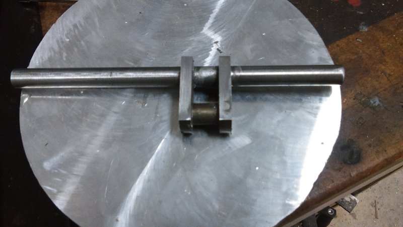
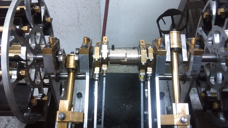
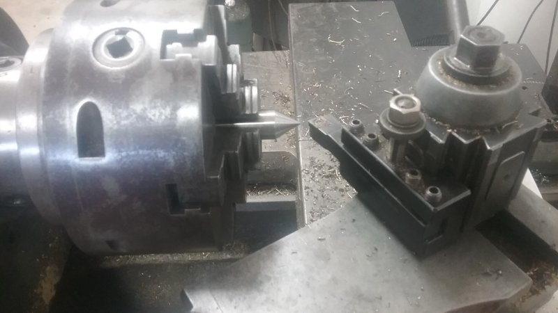
More work on the reverser today, turning the shaft between centers using one of the small lathe dogs I picked up in PA.

The first op was to take3 .25" of 5/16" brass rod. On one end turn down to .25" diameter for a length of 3/4", center drill, and thread the end 1/4-20 for 1/4" with a die. Turn the other end down to 1/4" for a length of 1" and center drill the end. This leaves 1.5" to be single point threaded 18tpi double start.

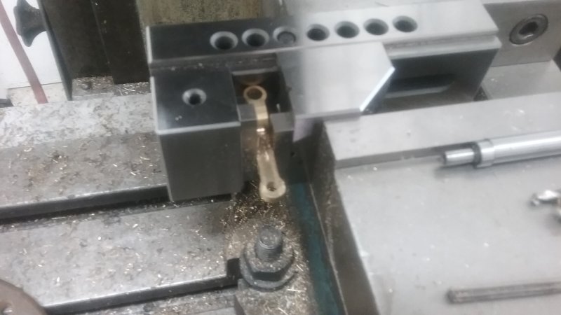
On the chuck end it's necessary to turn some round bar to a point with a 60 degree included angle. This is done with the compound set over 30 degrees. Before turning ensure that this center extends far enough out so that the dog's arm can contact the chuck jaws. Since I had the 1" section of the stock for clamping the dog, I had a good deal of adjustability.

large.jpg


Now I could mount the work and tighten the dog's screw. Things to check: that the threading bit can traverse the needed section to be threaded, and that the dog won't hit any part of the carriage or the tool.

large.jpg


Now I could do the threading as before using jaws 6 and 3 for the two starts. Previously on steel I had advanced the compound .100" to get a working thread, but I decided to cut both starts to .08", the check the fit on the nut and advance by .005 until it fit. With the dog it was quite easy to remove the work, test the fit, and replace for each pass. The final pass was at .095 with a spring pass on both starts.

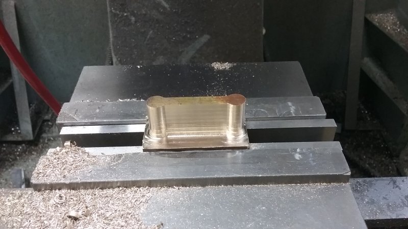
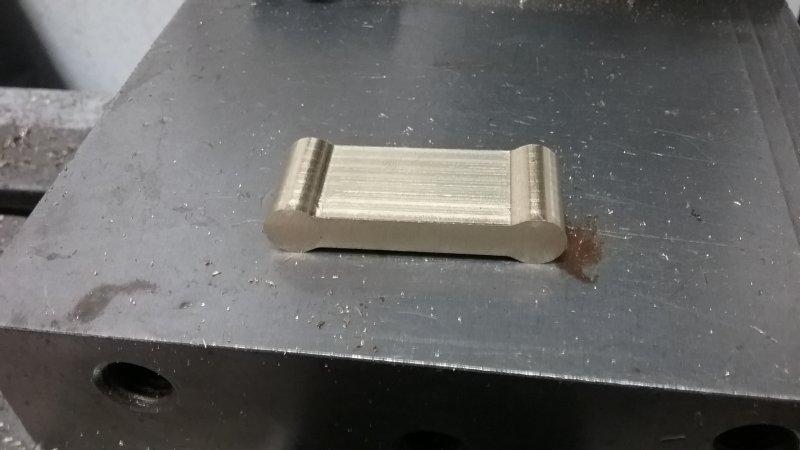
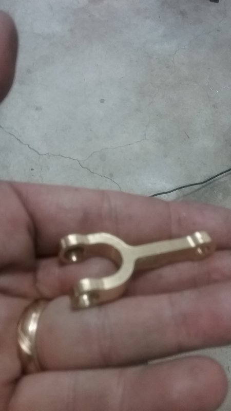
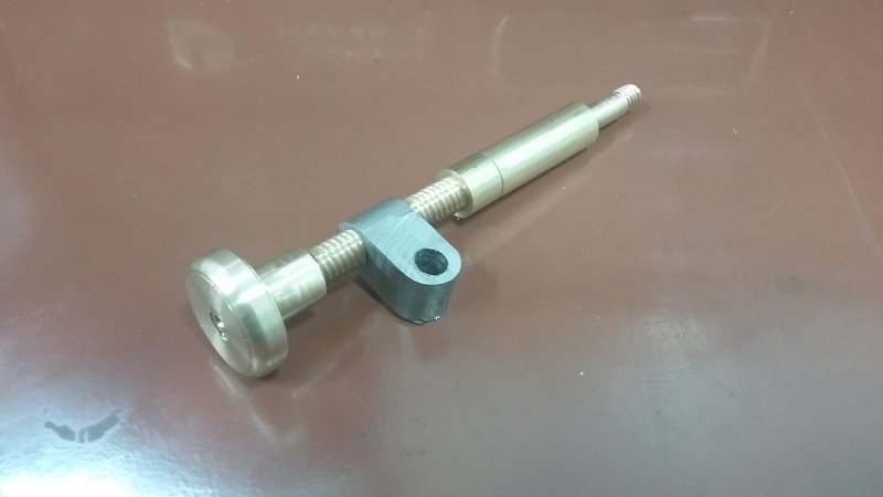
The remaining part to fabricate is the base of the shaft. It's a 2" piece of 7/16" brass rod that's turned down to 1/4" for a length of .75" and threaded 20 tpi with a die for .25". The other end is drilled 1" deep at .251 diameter. The end of the threaded shaft goes into this hole, and the top end will server as a stop for the nut at the full forward position. The bottom of the shaft passes through the bottom pivot and it secured with a nut.

large.jpg


Since I won't know the exact range that the nut will use on the thread until the reach rod is fixed to the weigh shaft, this design allows adjustment (I can shorten either the base or the screw or both. Eventually the shaft and base will be loctited together.

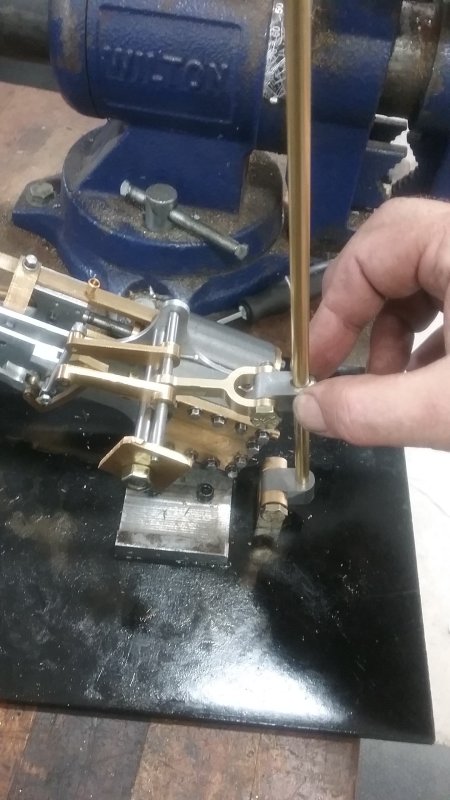
The same applies at the top, where the adjustment wheel will server as the stop once the full reverse position is known.

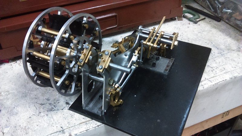
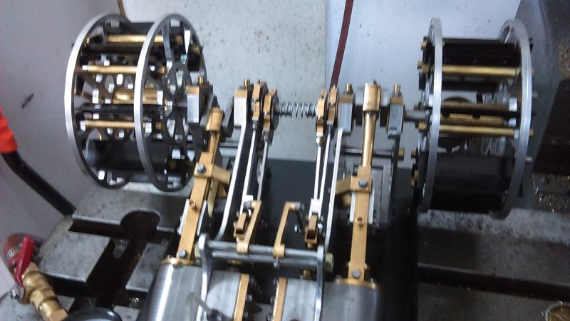
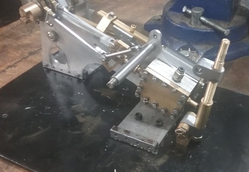
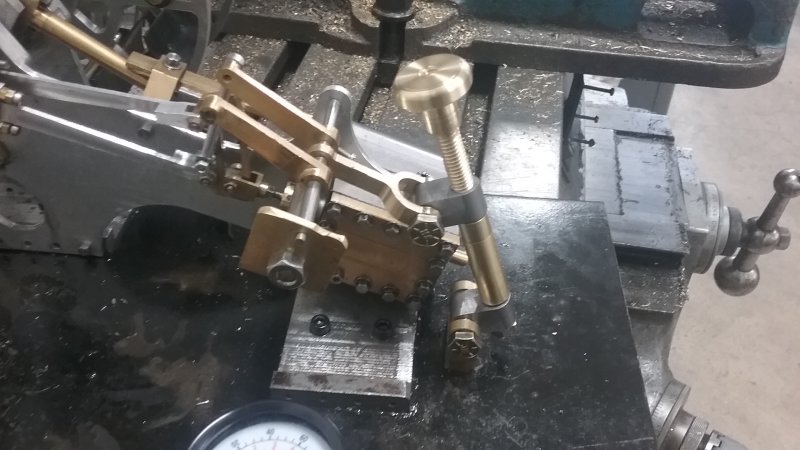
Initially I was going to place the reach rod at 180 degrees from the lifting links, but discovered that at full lift it would contact the steam chest. So it will be angled upward to clear.
 
Retimed the port engine and ran it solo in both directions, the hooked it up as a pair for a test run.

[ame]https://www.youtube.com/watch?v=EJ9DddBJOBA&feature=youtu.be[/ame]

This is at 18 psi. I'm continuing the run-in, and hope it will run slowly and continuously at Cabin Fever and/or NAMES next year.
 

Latest posts

Back
Top