ET Westbury Side Paddle Engine

Home Model Engine Machinist Forum

Help Support Home Model Engine Machinist Forum:

This site may earn a commission from merchant affiliate links, including eBay, Amazon, and others.
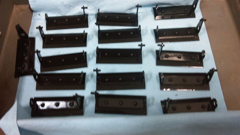
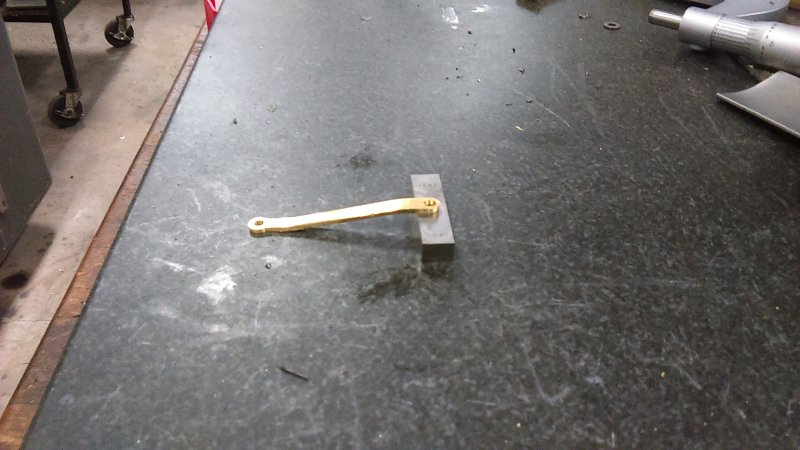
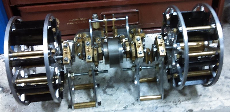
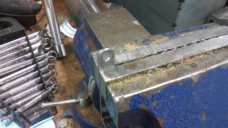
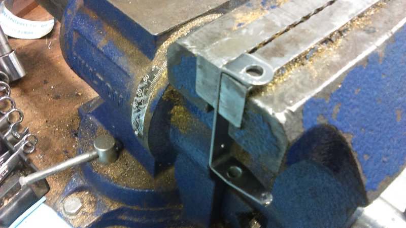
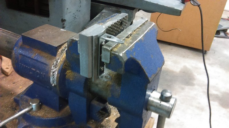
Starting to put the floats together. First need to bend the brackets. I use the bench vise and line up the scribed line with the top of the jaw, and hit it with a deadblow hammer.

large.jpg


large.jpg


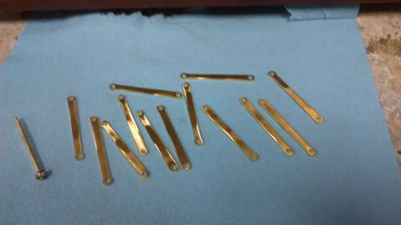
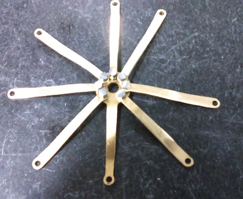
Next, use the die block to start the drive screws through the bracket.

large.jpg


With the ends of the screws exposed they can be aligned with the float and started using a small hammer.

large.jpg


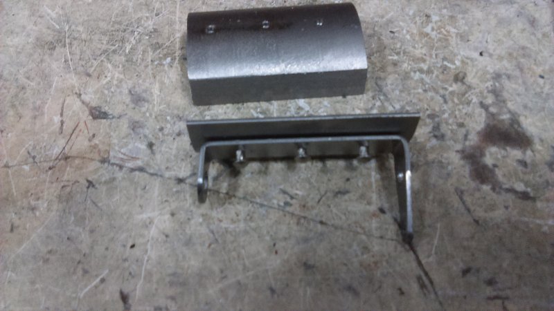
Drive the screw heads flush with the bracket using the vise and die block.

large.jpg


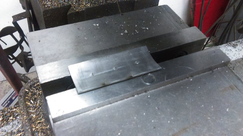
Clamp the bracket in the mill vise and mill off the protruding ends of the screws. I used a 1/2" ball nose mill for this.

large.jpg


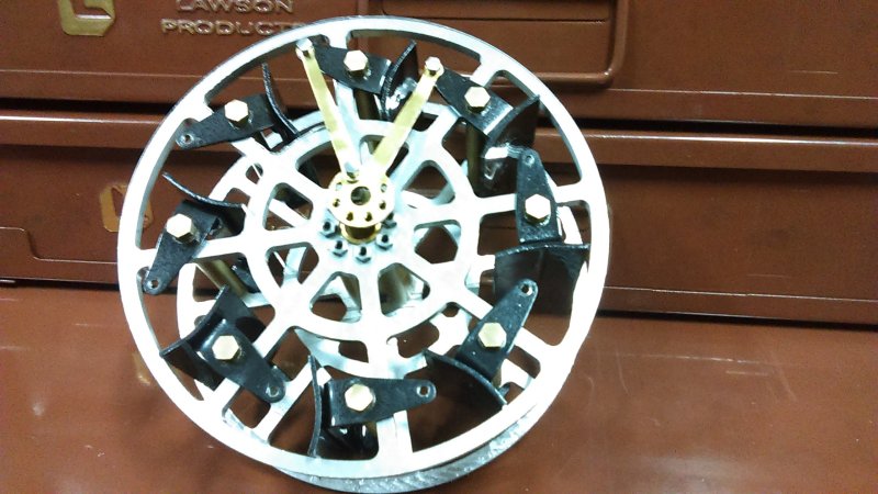
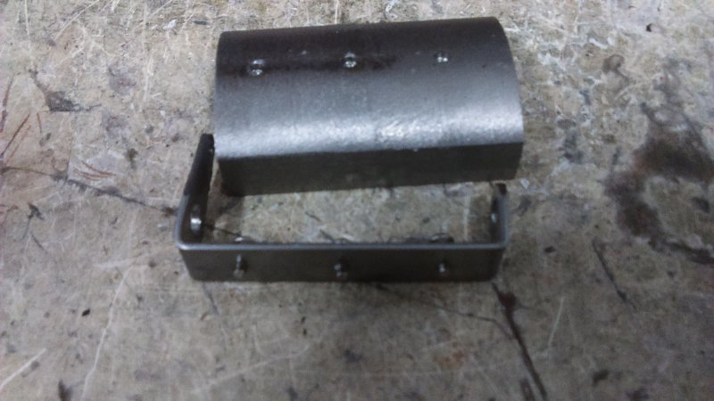
Test with paint. Using tractor implement spray paint; result looks good thus far.

large.jpg


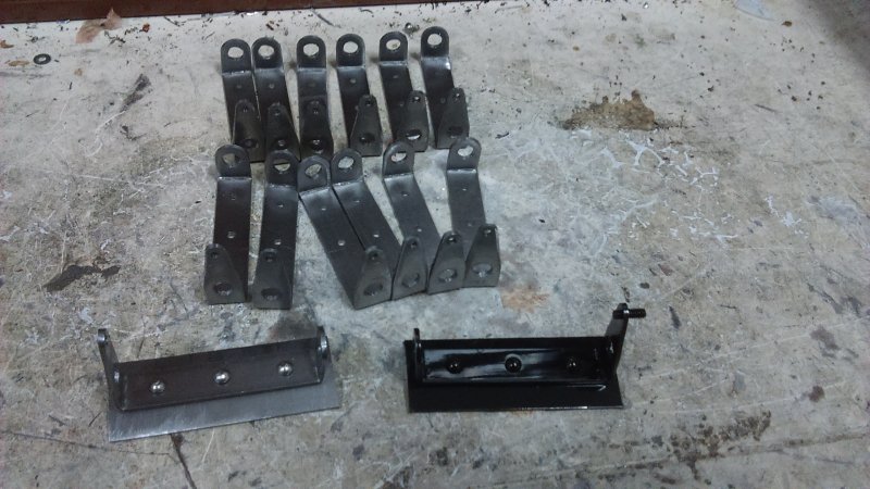
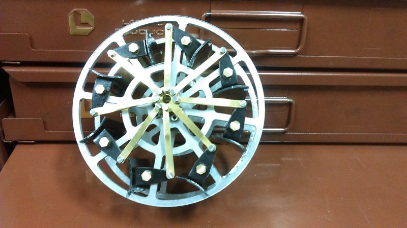
Should finish up the others and ready for paint next shop session. Still need to make two more brackets.
 
Last few times in the shop I managed to get all the floats assembled and painted:

large.jpg


The setscrew in the bracket is just to keep the paint out of the threads. Today I made the articulating arms/rods from some 1/16" C260 brass. Original plan was to make two across using 3/4" wide bars, but that would require a maximum 3/32" endmill to avoid cutting into the vise jaws; not having a 3/32, I elected to use 1/16. However, I broke two of these on the first piece of stock. I suppose the brass is sticky. Since I'd already cut off 7 pieces, I changed over to using a 5/32 endmill and cutting one arm from each piece. Then I used the same 5/32 to cut two across on 1" wide stock. Ended up with 15 (1 extra):

large.jpg


The one on the lower left is shown with a small pivot screw to test the fit.

Tomorrow I'll attempt a test assembly of one paddle. The arms still need to be bent to clear the master rod, so that will likely use the #1 eyeball tool.
 
Did a test assembly of one paddle:

large.jpg


No real problems, but I'll need to enlarge the pivot holes in the brackets a bit. They are only .005 larger than the screws, and not being lined up are too tight. One of the articulated arms is shown attached as well.

I did not mill the slots in the tops of the floats to clear the frames. Westbury said that they were not needed once he had assembled his, but left the drawings unaltered. They will be simple to add if I find them to be needed later.
 
Looking really great. Can't wait to see it in action.
 
To be honest I don't the the "action" of the feathering will be that impressive as the rotation is only a few degrees. The mechanism is interesting, however.
 
K,
Even though it might only be a few degrees, when used in water it makes a tremendous difference to how the floats produce more power.
Seeing the floats enter the water almost vertically and when at exactly the bottom they are perfectly upright, it is amazing how much more 'shove' they give.
If only the old Mississippi sternwheelers had taken up this idea they would have found much more driving power to their boats.
Lovely build BTW.

John
 
Thanks, John. Appreciate the compliment.

Assembled both paddles after enlarging the pivot holes in the brackets.

large.jpg


Bent the first of the articulating rods manually. The drop is supposed to be 1/4", so checked it with a gauge block and adjusted:

large.jpg


Then decide to try a test fit on one paddle with the master rod.

large.jpg


Ran into a problem as the articulating rod is not long enough to reach the float opposite the master without the float being able to rotate further. So it looks as it the slots in the floats will be needed. I'll have to disassemble the wheels once again to mill the slots allowing the extra rotation. rats.
 
Today was notch day in the shop. After measuring the separation of the frames and accounting for their thickness, I calculated that the centers of the frames are 2.04" apart. So after mounting the first test float in the bridgeport vise aligned on the Y axis, I found the center and machined the notches at +/- 1.02" on the DRO.

While Westbury used some sheet steel for the frames, mine were machined from 3/16" aluminum. To provide some wiggle room I used a 5/16" endmill. After the first seemed good, It was just a matter of taking each float off in turn, milling the notches, and reassembling to check fit. Rather tedious. It is important to realize that with the notches the float assembly loses symmetry, and the port and starboard floats are mirrored. Didn't screw that up so all the notches ended up on the correct side.

I now need to disassemble all of them again and repaint the bare metal of the notches.

I did verify that with the increased angle of pivot the articulated rod opposite the master rod now reaches its float arm.
 
After watching some football this afternoon I had a few hours in the shop. Disassembled the paddles once again, deburred the notches with the belt sander, and repainted.

Next, bent the first wheels articulated rod and attempted assembly of the first feathering eccentric "spider".

large.jpg


For reference, the central hole is 1/4" or ~12mm. The screw heads are 5/32 across the flats. As can be seen, the tolerances are very tight, and I found that when pivoting there is friction between the head of an articulating rod and its neighbors. I did some relieving with the belt sander on the last couple while assembling, but the rest will need to come off for the same treatment.
 
During the weekend having cut, deburred, and painted the floats, today's job was to reassemble the wheels. It gets a bit faster each time. I attached the rod assembly to the starboard side wheel:

large.jpg


Took a little doing, and learned a few things in retrospect. First, there's only about 2.5 threads here (40 tpi and 1/16 inch hole), so starting the tiny pivot screws was a challenge. When machining them I tested for fit with a nut, but a tapped hole is a tighter fit. Found that running the screw in solo seemed to enlarge the tapped threads a bit so that it was each to start afterwards with the arm involved.

The good news is that the articulating arms rotate very little with regard to their neighbors, so the tight fit is not a problem. Any contact should be smoothed out with running. In any case I was able to rotate the center hole of the master rod around to show the feathering action of the floats.

Heading out of town tomorrow for two weeks, so no more progress until I return. I'll finish up the port side rod assembly and then continue to get the port ending to run again. Then I'll need to swap the crankshaft on the starboard side and get it running. Afterwards it will be time for a base.
 
That looks amazing,i no longer have the patience to make these but they would finish my engine off,well done
Don
 
Thanks Bogs,ill consider that
Don
 
Back from my trip to Ecuador, and had a couple of hours in the shop the past few days. Some progress and more frustration.

1) Retimed valves on the port engine and tried on air. Runs in reverse but not forward. Still had lots of air leakage so I made new PTFE gaskets. Ran better in reverse but still not in forward. I also discovered that it needed flex in the main inner frame to run well. If I clamped both end of the frame in a vise to run it then it would bind up. So it seems I need to clamp a piece of straight bar to the bottom of the frame and readjust the motion.

2) Replaced the crankshaft on the starboard engine, which had been running OK in both directions. I needed a new longer crankshaft to mount the paddle. Now it's a bit stiffer, so I hooked it up on the lath to do a bit of running in. Went to check on it after an hour to find that the big end bearing on the conrod had come loose when the nuts worked off. Decided to call it a day.
 
Finished up the port paddle wheel today. Found out that the 1/8" plastic tube with 1/16" ID won't deliver enough pressure to run either engine, so I'll have to make do with the 1/4" tube for testing until I get around to actual piping.

I'll be interested to see how each engine runs with the paddles installed. The extra angular momentum should allow a slower speed, as currently both run way too fast.
 
Did a quasi assembly of the engine set. With the paddle wheels mounted and the cranks coupled, both turn pretty freely.

large.jpg


As can be seen I have temporary connectors for the inner and outer frames, made from some 1/4-20 threaded rod and some nuts/washers. The idea is to remove any flex between the frames and to keep the outer frames parallel. The spacers will be replaced once the engines run well and I can get accurate measurements.

I will be machining a length of steel bar as a spacer between the inner frames, again to avoid flexing and to keep the two frames parallel.

I am also considering replacing the screws that join the cylinder, inner frame, steam chest, and cover with studs (or at least some of them). Doing so will allow removal of the covers while retaining alignment of the other pieces. There are 12 screws on each side, so 24 such studs (5-40 x 2") would be needed.
 
Back
Top