- Joined
- Feb 25, 2008
- Messages
- 464
- Reaction score
- 5
Cross Slide Guide
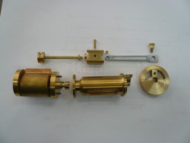
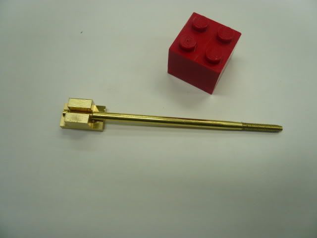
For the cross slide mechanism, Im using Doug Lanums design as described here. Dougs design is more rigid and looks more like the prototype engine than the one in the Village Press plans.
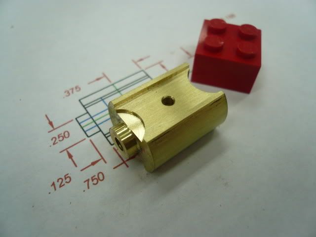
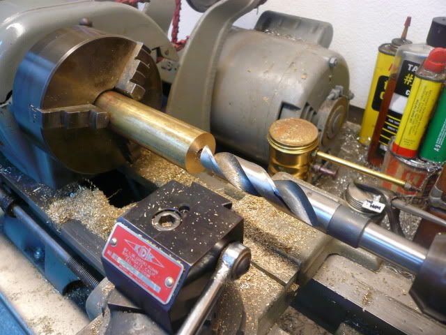
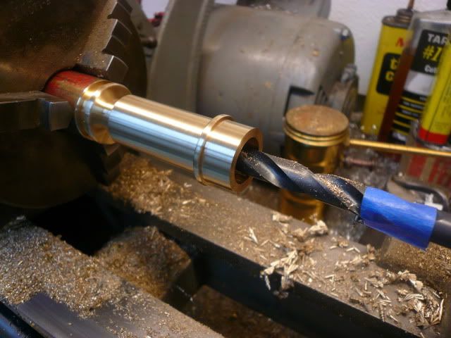
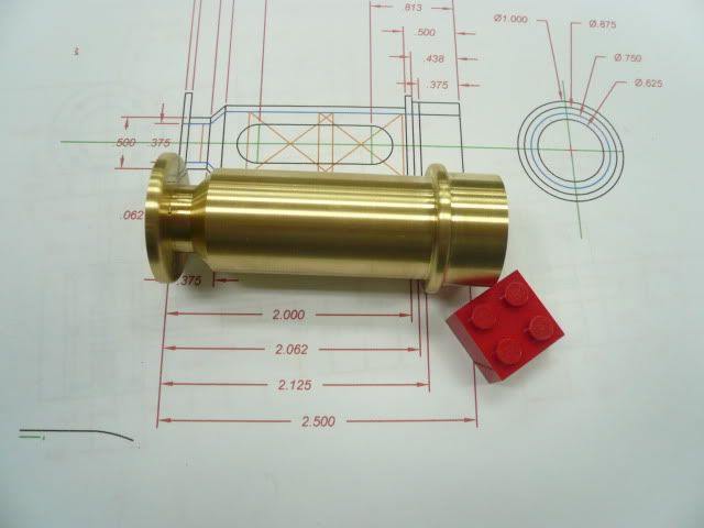
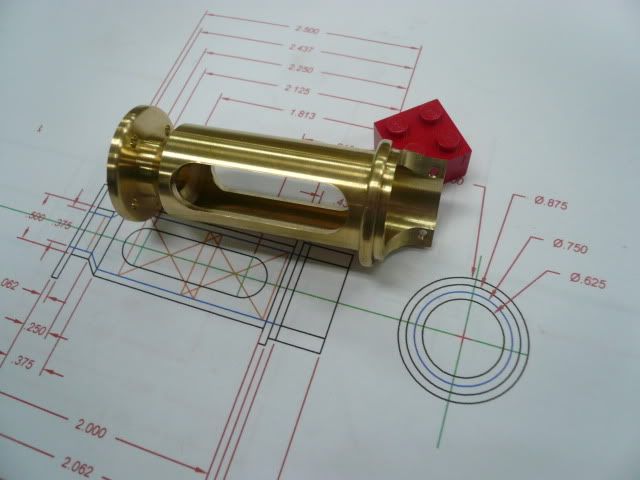
I did all of the lathe work in one set up. The finished cross slide guide is 2.500 long. I started with a 1 piece of brass rod and drilled and bored it 5/8D x 2.125 deep.
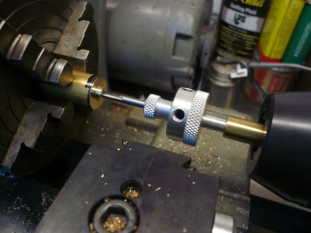
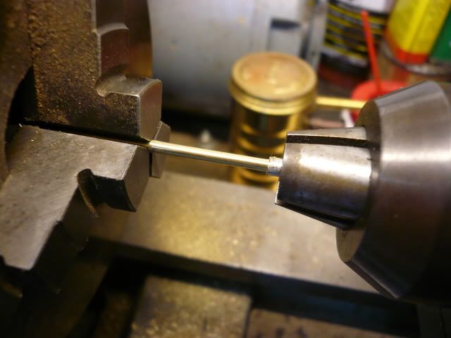
I then added the live center for support and turned the outside details. I used the compound set at 45 degrees to do the angle detail.
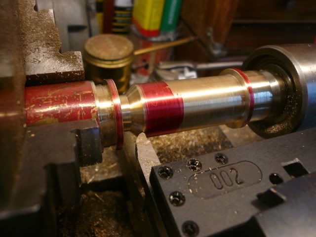
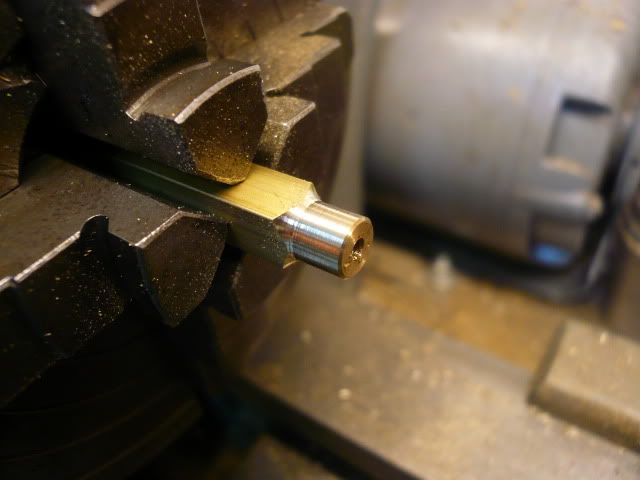
Round the flange and decorative ring with a file and complete the center bore by drilling a 3/8 hole for the valve rod/packing gland to pass through.
Part off and the lathe work is finished.
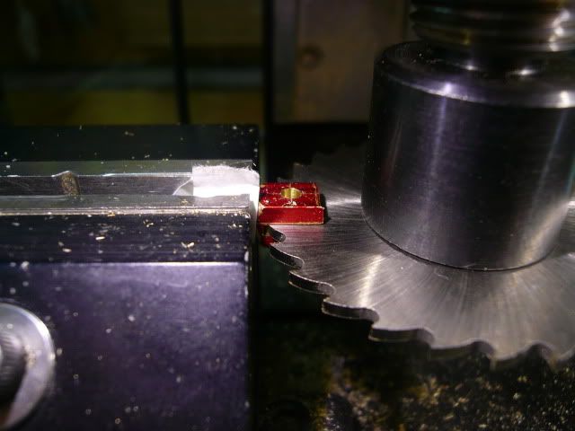
The rest of the guide is done on the mill. The first step is to saw off the excess material on the end (faster than milling).
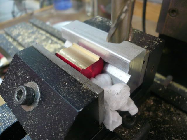
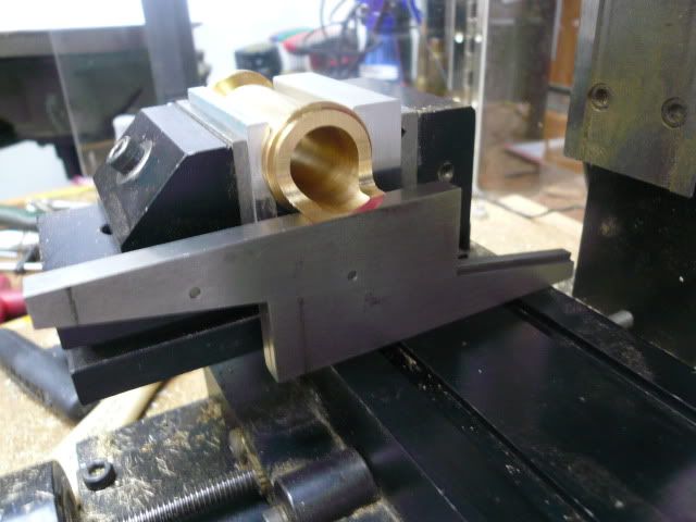
Then clamp in the mill vise and mill the flat where the cross slide guide mounts to the horn plate.
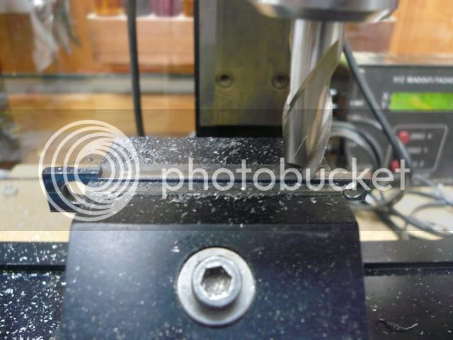
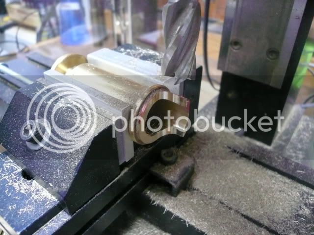
Without moving the part in the vise, switch to a 1/2" mill and mill the end contour.
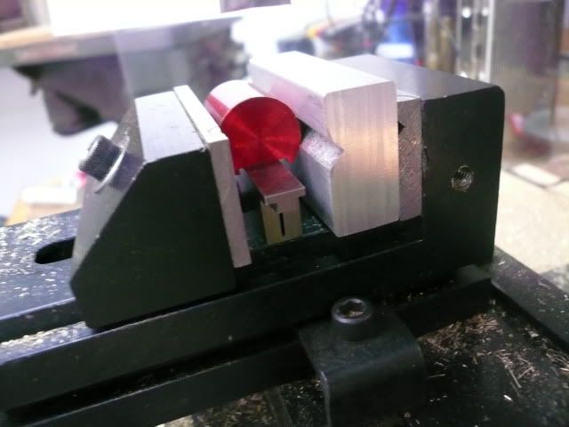
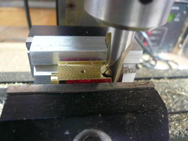
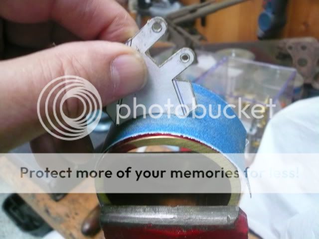
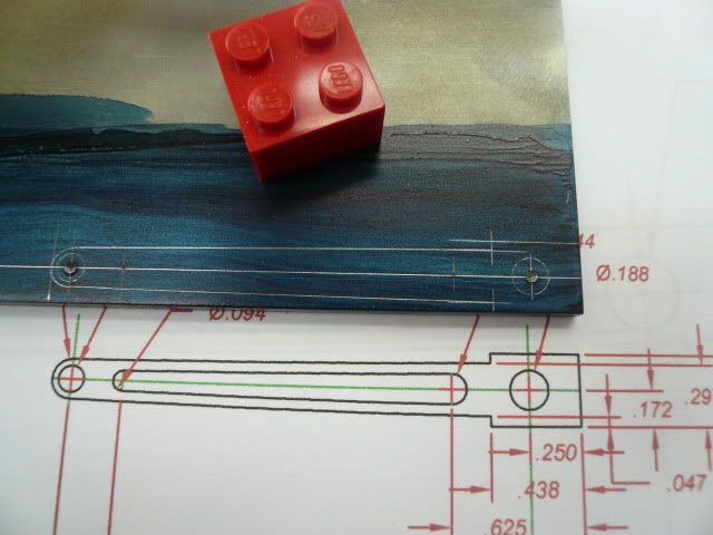
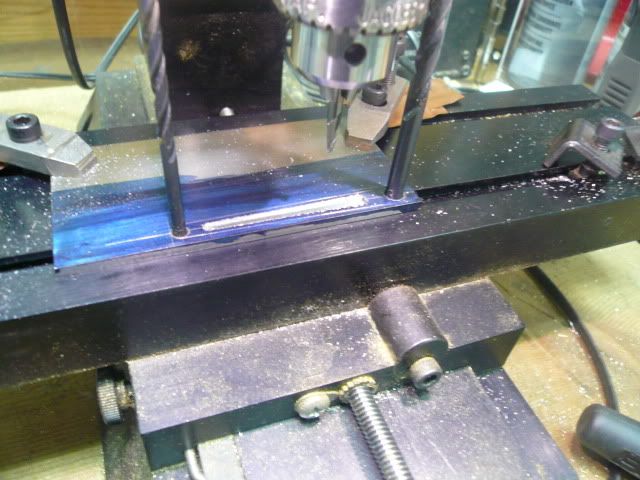
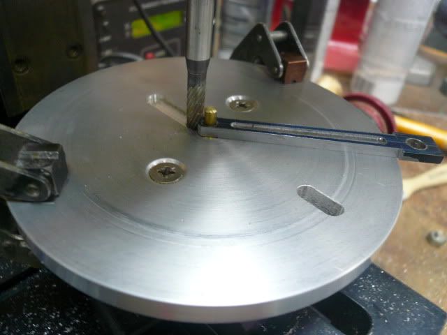
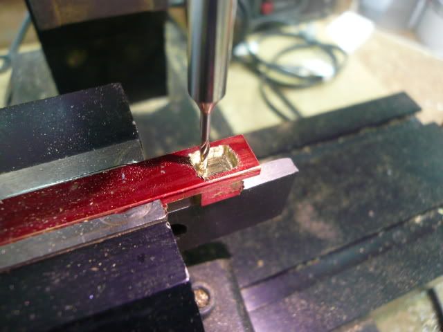
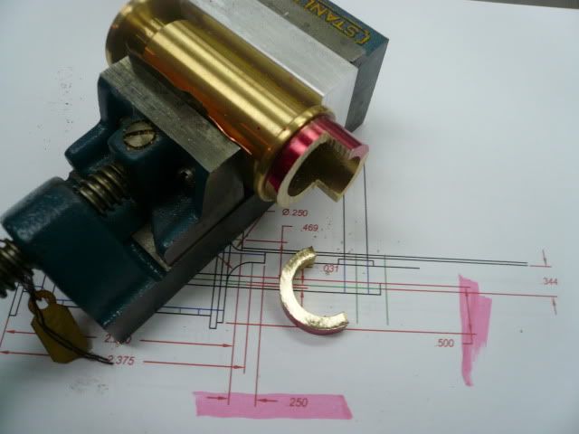
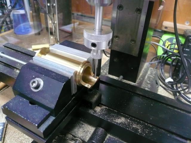
Rotate the part 90 degrees to drill the two 2-56 mounting holes and the side openings. I used an adjustable parallel to get the correct rotational setting.
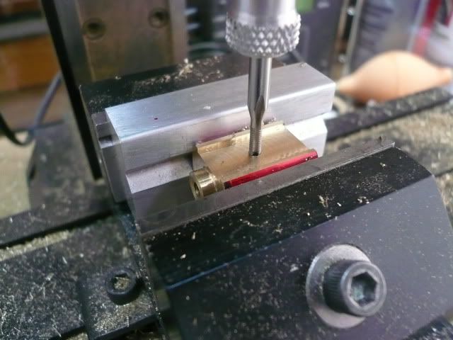
Drill and tap the two 2-56 mounting holes.
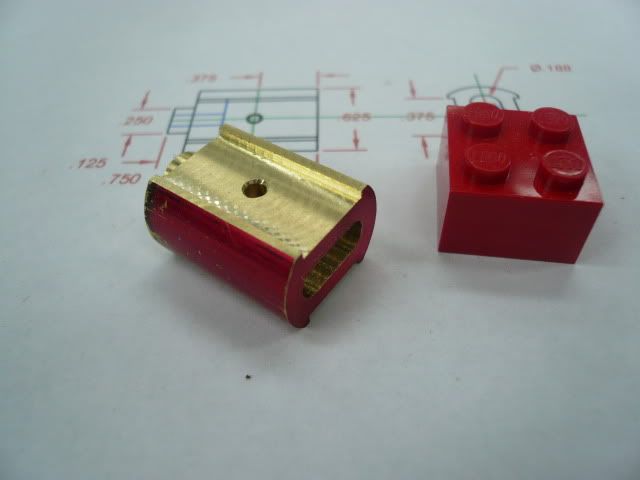
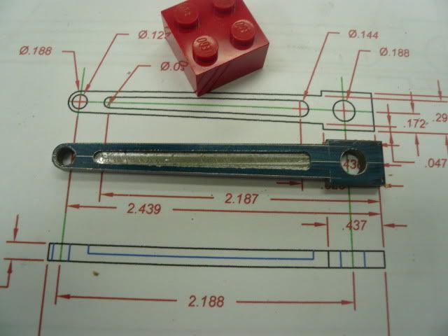
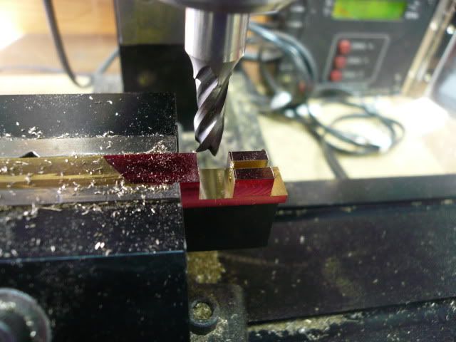
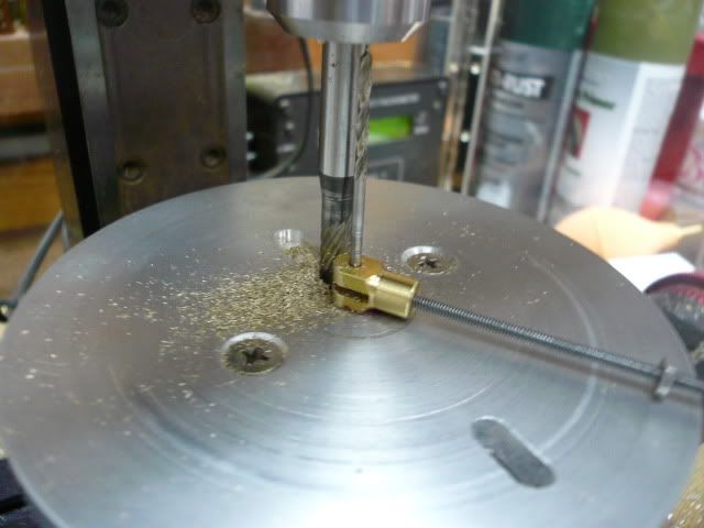
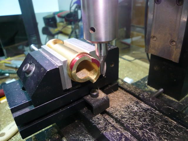
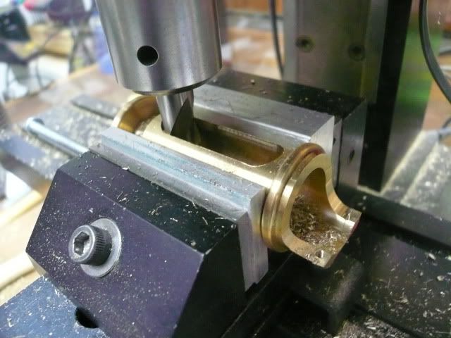
Then cut the side openings with a 3/8 mill. I did this by taking light, full cutter-width passes through the top surface and then on through the bottom.
Using the cylinder head holes as a guide, drill the four mounting holes in the flange.
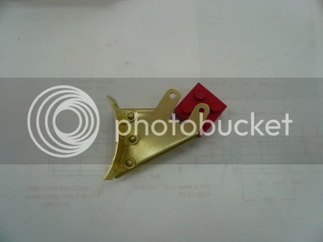
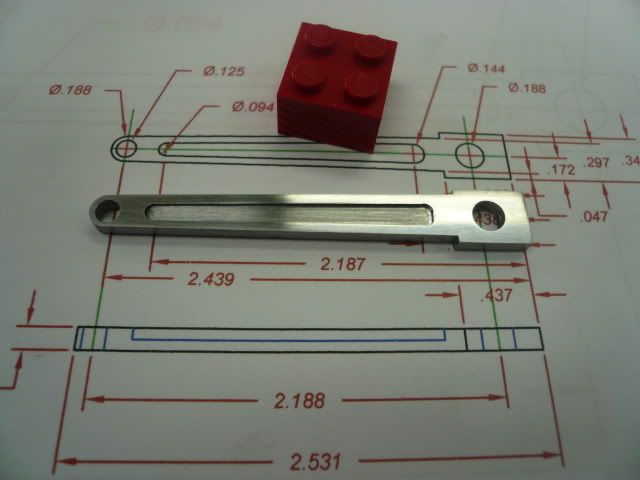
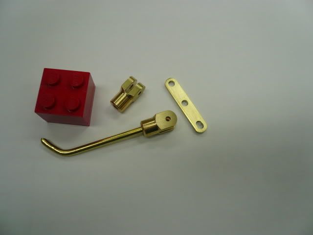
That finishes the machine work. The sharp edges on the sides and near the mount will be rounded and blended later.
I had planned to use 2-56 brass hex head screws for assembly, but discovered that I didnt leave enough room to get them in the holes. Drat!
There are a couple of ways to work around the problem. One is to use studs. Thats what Ill do if I can find some decent scale 2-56 nuts. The other is to just enlarge the holes enough to get the hex head screws in. This should be an okay work around because the boss on the cylinder head provides the registration.
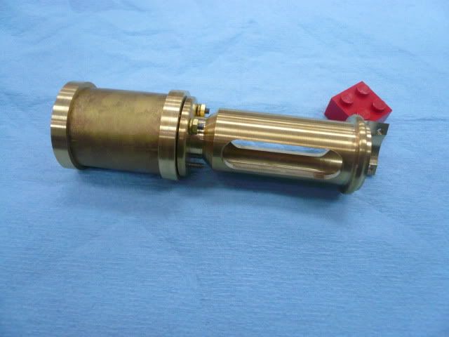
Two other things to consider if you make this: one, make the flange flat where the bolts land (Mine has a slight slope. Itll be okay, but would be better flat.) and two, leave another quarter inch on the end where the cross slide guide screws to the hornplate. A little extra length there will allow for a nicer transition between the guide and the hornplate.
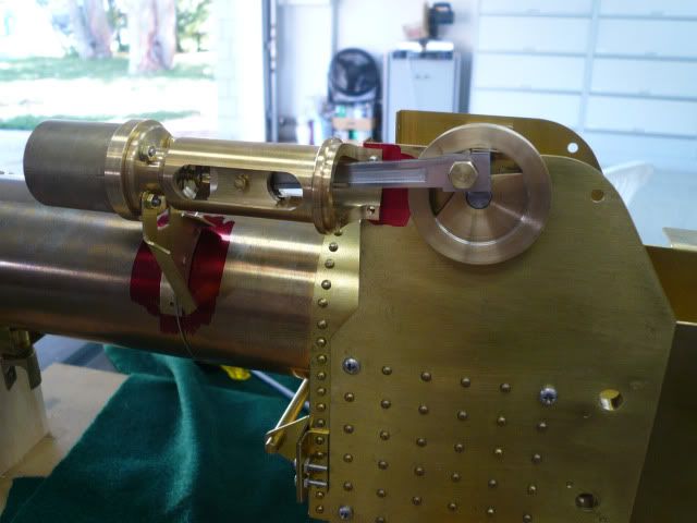
I think this is going to be a very noticeable enhancement to my tractor and just want to thank Doug Lanum again for sharing the idea. If youre out there Doug Thanks!
Dennis
For the cross slide mechanism, Im using Doug Lanums design as described here. Dougs design is more rigid and looks more like the prototype engine than the one in the Village Press plans.
I did all of the lathe work in one set up. The finished cross slide guide is 2.500 long. I started with a 1 piece of brass rod and drilled and bored it 5/8D x 2.125 deep.
I then added the live center for support and turned the outside details. I used the compound set at 45 degrees to do the angle detail.
Round the flange and decorative ring with a file and complete the center bore by drilling a 3/8 hole for the valve rod/packing gland to pass through.
Part off and the lathe work is finished.
The rest of the guide is done on the mill. The first step is to saw off the excess material on the end (faster than milling).
Then clamp in the mill vise and mill the flat where the cross slide guide mounts to the horn plate.
Without moving the part in the vise, switch to a 1/2" mill and mill the end contour.
Rotate the part 90 degrees to drill the two 2-56 mounting holes and the side openings. I used an adjustable parallel to get the correct rotational setting.
Drill and tap the two 2-56 mounting holes.
Then cut the side openings with a 3/8 mill. I did this by taking light, full cutter-width passes through the top surface and then on through the bottom.
Using the cylinder head holes as a guide, drill the four mounting holes in the flange.
That finishes the machine work. The sharp edges on the sides and near the mount will be rounded and blended later.
I had planned to use 2-56 brass hex head screws for assembly, but discovered that I didnt leave enough room to get them in the holes. Drat!
There are a couple of ways to work around the problem. One is to use studs. Thats what Ill do if I can find some decent scale 2-56 nuts. The other is to just enlarge the holes enough to get the hex head screws in. This should be an okay work around because the boss on the cylinder head provides the registration.
Two other things to consider if you make this: one, make the flange flat where the bolts land (Mine has a slight slope. Itll be okay, but would be better flat.) and two, leave another quarter inch on the end where the cross slide guide screws to the hornplate. A little extra length there will allow for a nicer transition between the guide and the hornplate.
I think this is going to be a very noticeable enhancement to my tractor and just want to thank Doug Lanum again for sharing the idea. If youre out there Doug Thanks!
Dennis