Once again guys, thanks for the comments. They're really appreciated.
Slip Eccentric
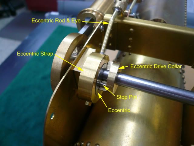
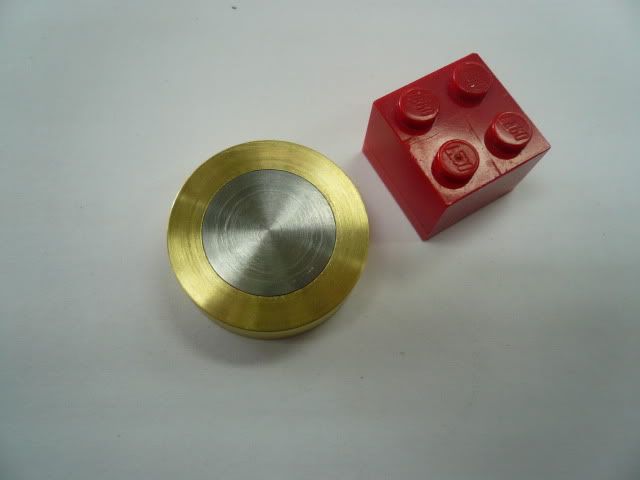
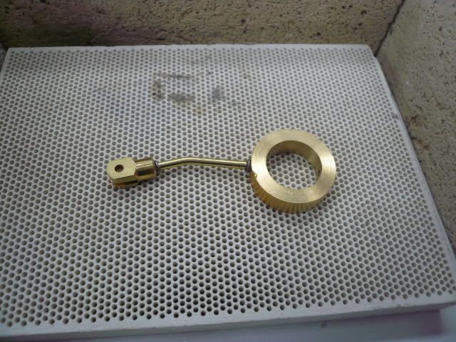
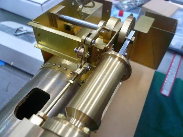
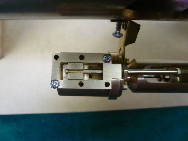
Rudys tractor uses a slip eccentric for valve motion. It allows the engine to rotate in either direction using just one eccentric. The major components are an eccentric strap, eccentric and eccentric drive collar. Heres an after picture to give you an idea of what the pieces are and where they go.
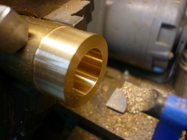
The eccentric strap is a 1 OD, 5/8 ID brass ring. The ID is a running fit with the eccentric so it should have a smooth finish. ID isnt overly critical because the eccentric will me made to fit the strap.
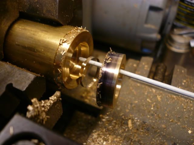
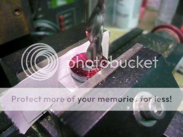
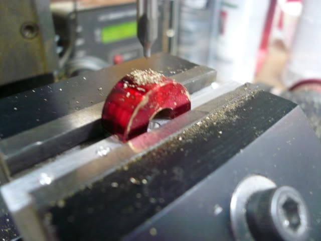
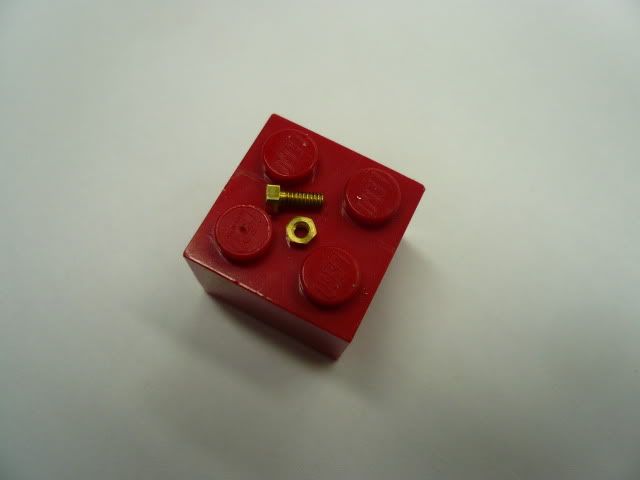
The following picture doesnt add any info, but its so rare for me to have something part off cleanly that theres no way this photo wasnt going into the post. Why cant it always be like this??
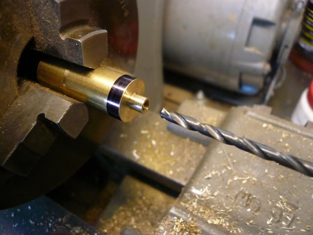
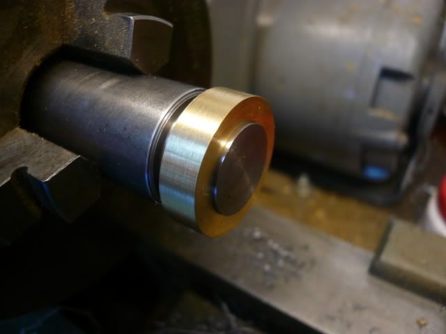
The eccentric is turned from steel and is a running fit with the eccentric strap. I used the strap as a gauge to get the correct eccentric diameter. Once the fit is good, cut a groove for the screw point that holds the ring on the eccentric and then part off.
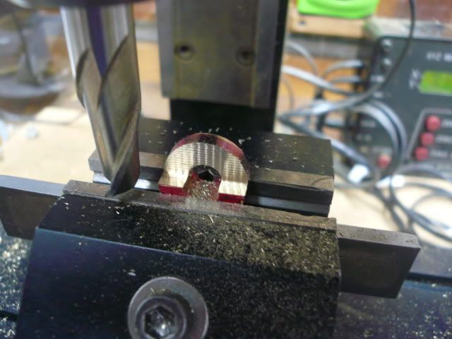
The eccentric gets its eccentricity from a 1/4" hole reamed 1/8 off center. I used a wiggler to find the center of the eccentric using the parting lines for reference, and then the mill readout to move over 1/8. Compared to some of the eccentrics Ive seen on this site this is a pretty simple one.
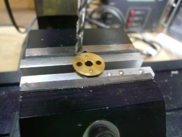
To complete the eccentric, and before removing it from the mill, drill and tap a 2-56 hole 3/32 off the center point directly opposite the 1/4" hole. This hole is for the stop pin that will engage the eccentric drive collar.
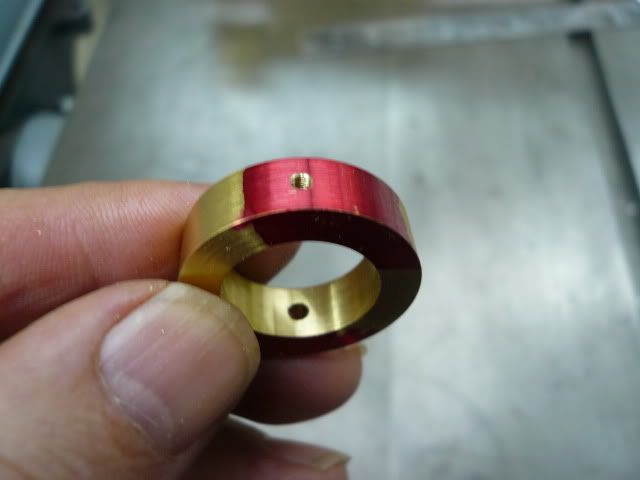
The eccentric strap machining is finished off with a drilled 3/32 hole for the eccentric rod and a 2-56 tapped hole for the screw that engages the groove in the eccentric. The screw and groove keep the ring on the eccentric.
Heres the completed eccentric and eccentric strap.
The eccentric rod and eye are soft soldered to the eccentric ring. I used solder preforms to help control the solder.
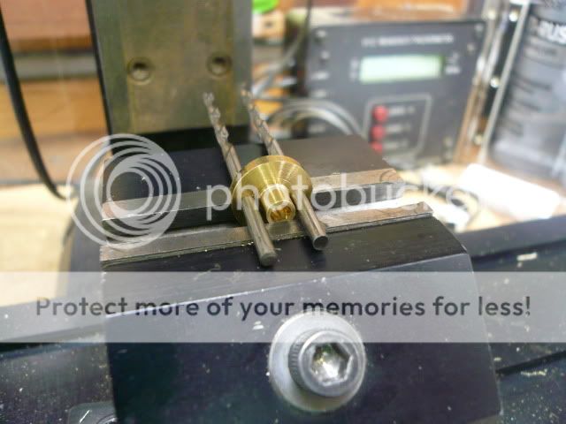
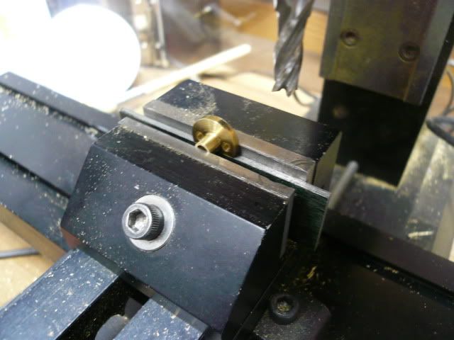
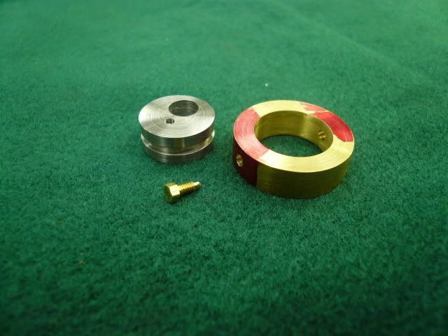
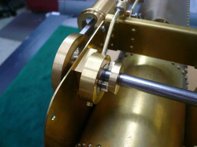
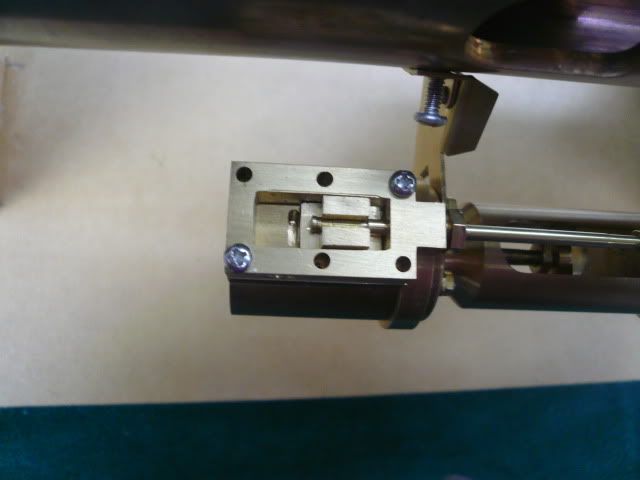
The eccentric drive collar is 1/2" diameter and 1/4" wide with a 1/8 wide step milled in it. The step depth is initially cut to 15/64 and, per the plans, may have to be adjusted later to get correct valve movement. I milled the step first,
then reversed the collar on a sacraficial parallel to drill and tap a 6-32 hole for the setscrew that locks the collar to the drive shaft.
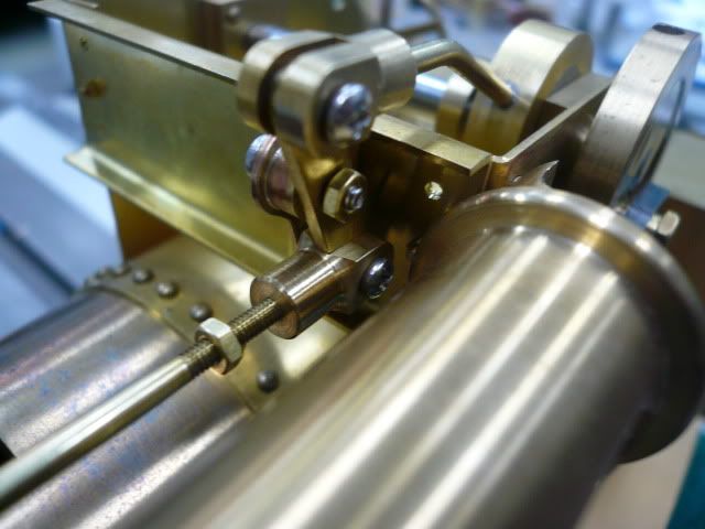
And heres the completed slip eccentric ready to install the linkage. Based on what the plans say, this will be coming apart a few times in a slow and tedious process of adjusting the drive collar step to get the right valve movement.
It took me a while to get my head around how this works, but I think Ive got it now. To reverse the engine, you stop it and manually turn the crankshaft about a half turn opposite the direction it was running. This will engage the other side of the drive collar step but will not move the valve. However, the crankpin will have moved to the other side of dead center. When the steam is turned on again the piston continues in the same direction it was, but because the crankpin is on the other side of dead center, the engine rotation will be reversed. Clear as mud, right?
Dennis


 Yeah, I went to "The Pipe Ranch" and asked for a foot of 4". They went to the short-end pile, picked up the shortest piece and handed it to me. I figure I'll have several feet of indestructible small-stock racking in a bit..