I really appreciate you guys taking the time to comment on my progress. It's very gratifying. Thank you.
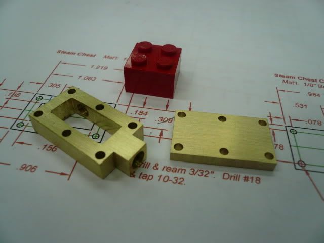
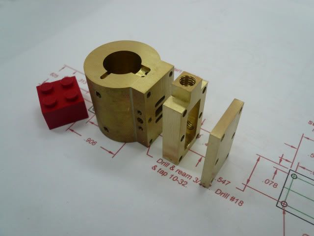
Cylinder Block
I wasnt sure how to approach fabricating the cylinder so I asked for help from HMEM members and as usual they came through (thread
here ). Lots of helpful ideas and approaches. Thanks, guys. Heres how I ended up doing it.
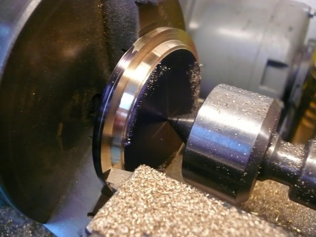
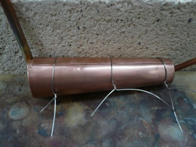
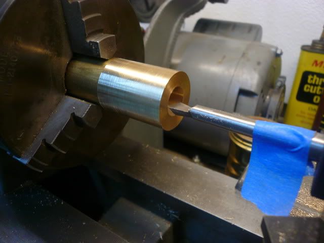
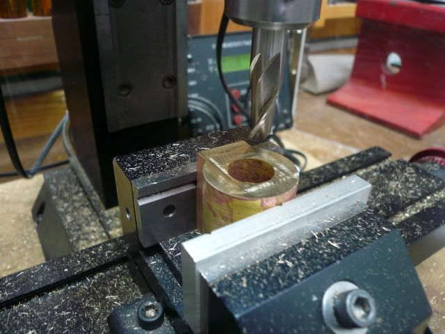
The cylinder is 1 1/16 long and 1 in diameter. Bore is 0.500 and stroke is 0.625. I used an overlong piece of 1 brass to give me something to hold onto (thanks bearcar1) and drilled and reamed to 0.500.
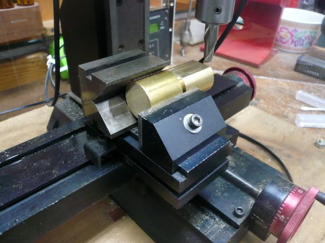
Then went to the mill and milled a flat for the valve plate (not sure what else to call it).
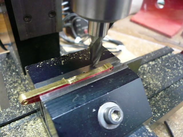
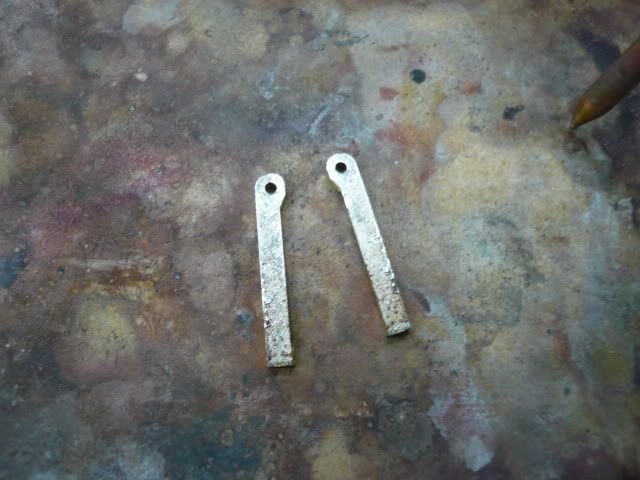
The valve plate is just a piece of 1/4" bar stock milled to 5/8 x 1 1/16. Here its in position and drilled and pinned with two 1/16 brass rods. The rods are to hold the plate in place during silver soldering.
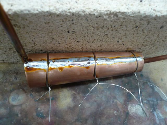
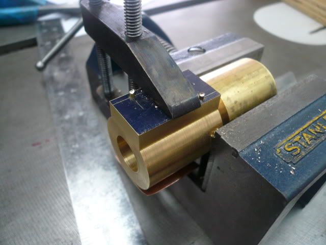
I put a prick punch dimple in each of the four corners to provide clearance for the solder, cleaned everything with solvent and water and detergent, fluxed the joint and pre-positioned small flattened bits of silver solder, then heated the joint using two disposable tank propane torches. My wife (bless her) held one and I held the other.
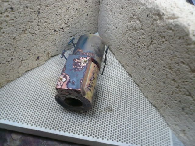
From what some of you have told me, the black indicates that I probably left the heat on a little longer than I should have. Still learning.
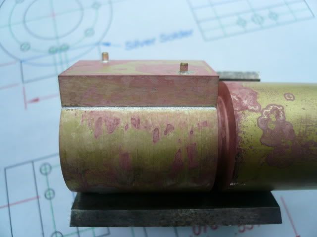
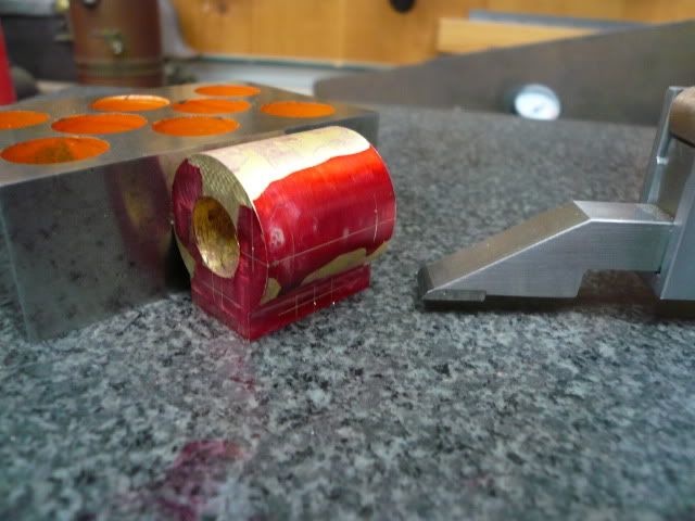
Heres the part after a half hour in citric acid pickle.
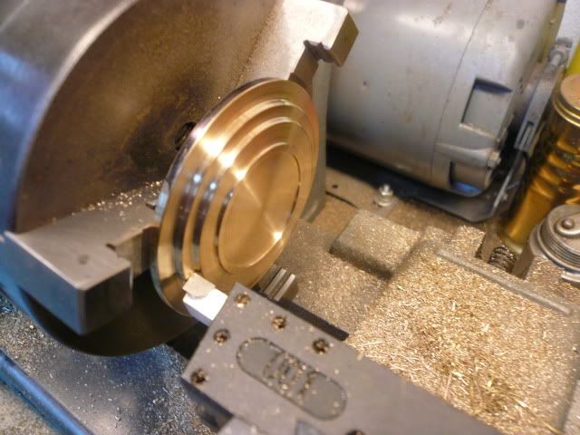
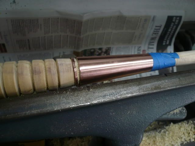
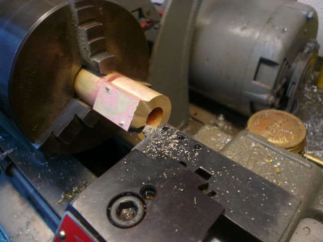
Then it was back to the lathe to face the end.
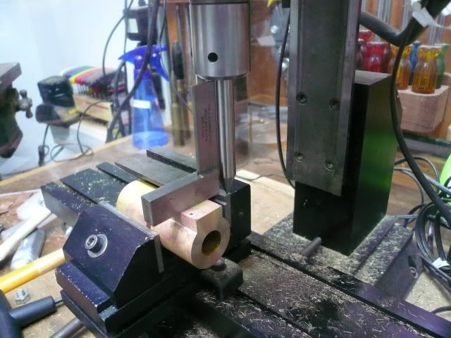
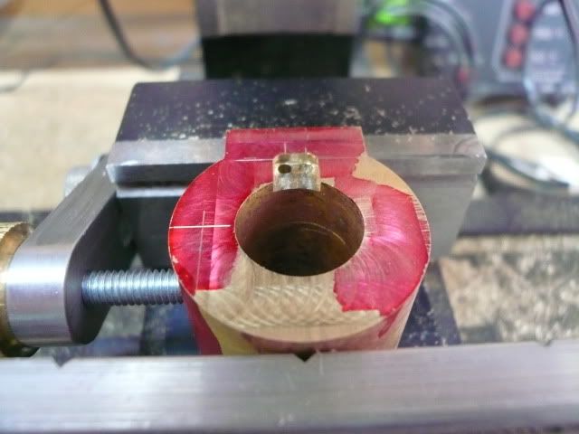
After facing the part clamped square in the mill vise,
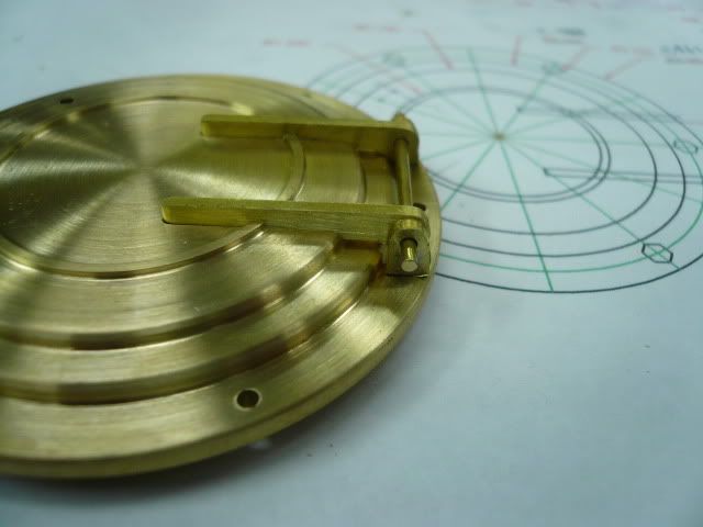
and the valve port face was milled flat. I was pleased to see how well the positioning pins disappeared.
At this point, the excess bar stock was sawed off and the other face of the cylinder block was milled flush.
It turns out this step could have been done in the lathe. At the time, I didnt realize that the valve plate would fit nicely between two jaws of my three jaw and that the part could have been easily chucked up for facing.
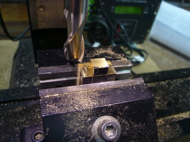
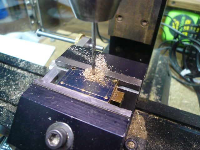
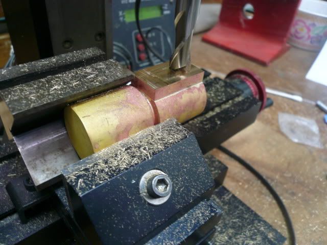
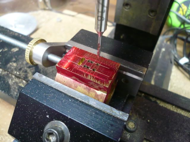
With all the surfaces flat, the ports and holes were layed out,
and drilled an milled. This is one of the steam passages (there are actually two holes, one is full of swarf).
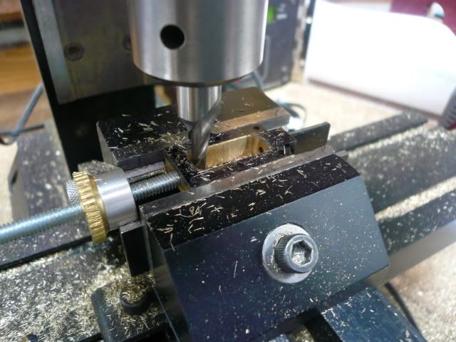
The outer ends of the valve ports were drilled first and then the material between them was milled out using a 1/16 mill and lots of light cuts.
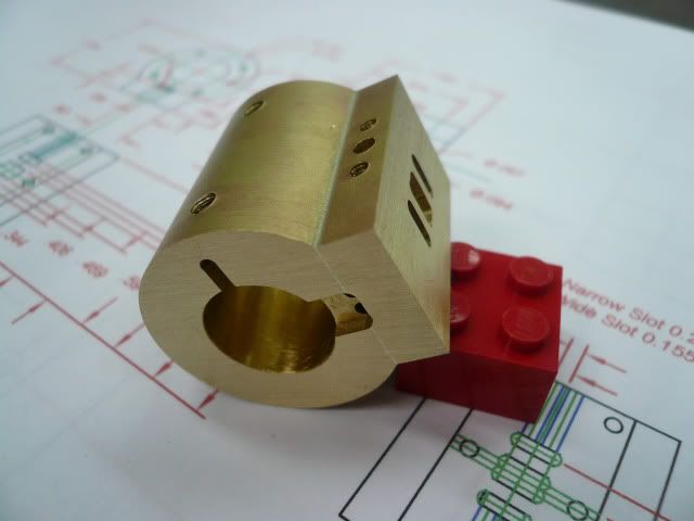
And heres the finished cylinder block.
This was a complicated part for me, thank you again for the good ideas shown in the thread I referenced earlier. The ideas really helped.
I'm going on vacation for a couple of weeks, so it'll be awhile before my next post. Thanks again for following along.
Dennis


")