- Joined
- Feb 25, 2008
- Messages
- 464
- Reaction score
- 5
Ive started a build of Rudy Kouhoupts Model Steam Tractor. The tractor is 3/4 scale and is loosely based on the J.I. Case steam engines. To quote Rudy,
it is not an exact scale replica. Some of the parts have been arranged to improve the ease of construction of the model or to insure its dependable operation. The part about ease of construction was strangely appealing.
I purchased a set of plans that have been recently published by Village Press. This will be the first engine I intend to operate with steam, so having plans to work from should be a good thing. My plan is to build the rear wheels first (they look like the hardest part to me) and if that goes well then proceed with the rest of the engine.
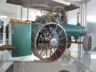
Interestingly, Rudys original engine, which he built for his Popular Mechanics article (Feb. 1971), is at the Craftsmanship Museum in Vista, CA. The museum is about 40 miles from me. I expect to make several trips there as this build goes along. Heres a photo I took of it.
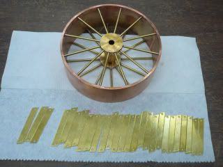
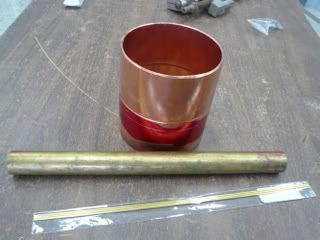
The rear wheels are supposed to be brass, 4 1/2 OD & 4 1/4 ID, fabricated from a cast-brass pipe adapter. Good luck finding one. The closest I could come in brass was a threaded specialty connector for $148 and I would need two!! Im barely started and I have to deviate from the plans. However, I guess being able to do that is part of the beauty of model engineering and of not building an exact replica. Anyway, I ended up selecting a 4 copper sweat fitting that is 4.350 OD and 4.136 ID. Close enough. Thirty-eight bucks, but I get two wheels from one fitting. The other raw materials are 1 brass rod for the hub and 3/32 rod for the spokes.
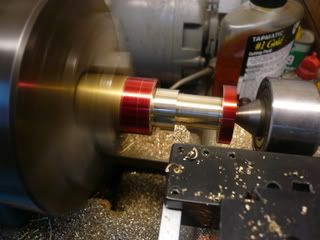
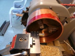
For the rims, I cut two 1 1/2" wide rings from the coupling.
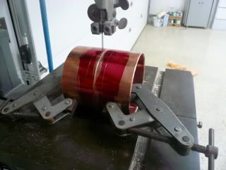
Since Ive only got a 6 lathe, I had to get creative to face the edges (Rudy says this can be done with a file!?).
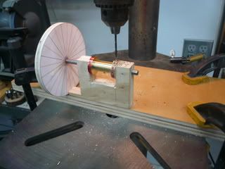
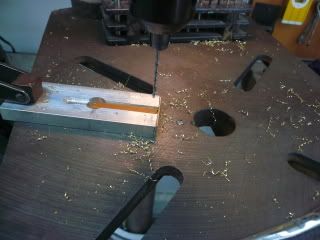
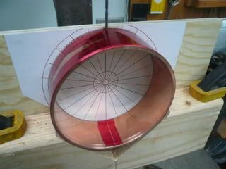
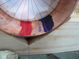
Next step spoke holes. There are 24 spokes per wheel, twelve to a side, staggered so the two sides are off-set. To drill the holes I layed out the spoke pattern and glued it to a wood fixture (Im a big fan of wood for one-time fixtures). The way this one works is the black lines represent one sides spokes and the red the other. Line up the reference line on the inside of the rim with either a red or black line, drill, move the reference to the next line of the same color and so on. Then reverse the rim and drill the other side using the opposite color lines. I first spot drilled and then thru drilled.
Drilling the copper didnt go so well until I got some info from helpful people on this board (see thread on Drilling Copper). The trick is slower speed (1000 rpm or slower) and coolant (preferably tallow).
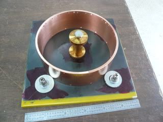
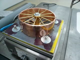
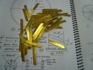
Each wheel has 24 grouters fastened with rivets. Theyre fastened such that two of them fall between each spoke. Rudys suggestion was to drill the holes on one side of the rim and then use the grouter as a guide to line drill the other side during assembly.
The rivets will be 1/16, but I used a #51 drill which makes it just a little easier to get the rivets in. I used the same drill fixture as for the spoke holes, but used a new reference line set off the proper distance from the original reference. Then I aligned the new mark with each of the spoke lines, spot drilled and then thru drilled.
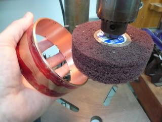
After the holes were all drilled, I deburred the inside using a 3 diameter scotchbrite wheel in the drill press.
Next thing to tackle are the hubs. So far so good.
Regards,
Dennis
P.S. I tried smaller photos for this post. Are these the right size or should I go back to larger ones??
I purchased a set of plans that have been recently published by Village Press. This will be the first engine I intend to operate with steam, so having plans to work from should be a good thing. My plan is to build the rear wheels first (they look like the hardest part to me) and if that goes well then proceed with the rest of the engine.
Interestingly, Rudys original engine, which he built for his Popular Mechanics article (Feb. 1971), is at the Craftsmanship Museum in Vista, CA. The museum is about 40 miles from me. I expect to make several trips there as this build goes along. Heres a photo I took of it.
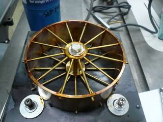
The rear wheels are supposed to be brass, 4 1/2 OD & 4 1/4 ID, fabricated from a cast-brass pipe adapter. Good luck finding one. The closest I could come in brass was a threaded specialty connector for $148 and I would need two!! Im barely started and I have to deviate from the plans. However, I guess being able to do that is part of the beauty of model engineering and of not building an exact replica. Anyway, I ended up selecting a 4 copper sweat fitting that is 4.350 OD and 4.136 ID. Close enough. Thirty-eight bucks, but I get two wheels from one fitting. The other raw materials are 1 brass rod for the hub and 3/32 rod for the spokes.
For the rims, I cut two 1 1/2" wide rings from the coupling.
Since Ive only got a 6 lathe, I had to get creative to face the edges (Rudy says this can be done with a file!?).
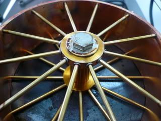
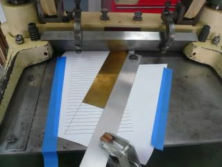
Next step spoke holes. There are 24 spokes per wheel, twelve to a side, staggered so the two sides are off-set. To drill the holes I layed out the spoke pattern and glued it to a wood fixture (Im a big fan of wood for one-time fixtures). The way this one works is the black lines represent one sides spokes and the red the other. Line up the reference line on the inside of the rim with either a red or black line, drill, move the reference to the next line of the same color and so on. Then reverse the rim and drill the other side using the opposite color lines. I first spot drilled and then thru drilled.
Drilling the copper didnt go so well until I got some info from helpful people on this board (see thread on Drilling Copper). The trick is slower speed (1000 rpm or slower) and coolant (preferably tallow).
Each wheel has 24 grouters fastened with rivets. Theyre fastened such that two of them fall between each spoke. Rudys suggestion was to drill the holes on one side of the rim and then use the grouter as a guide to line drill the other side during assembly.
The rivets will be 1/16, but I used a #51 drill which makes it just a little easier to get the rivets in. I used the same drill fixture as for the spoke holes, but used a new reference line set off the proper distance from the original reference. Then I aligned the new mark with each of the spoke lines, spot drilled and then thru drilled.
After the holes were all drilled, I deburred the inside using a 3 diameter scotchbrite wheel in the drill press.
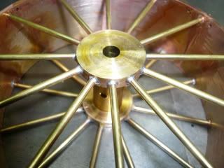
Next thing to tackle are the hubs. So far so good.
Regards,
Dennis
P.S. I tried smaller photos for this post. Are these the right size or should I go back to larger ones??
")