Building Rudy's Steam Tractor

Home Model Engine Machinist Forum

Help Support Home Model Engine Machinist Forum:

This site may earn a commission from merchant affiliate links, including eBay, Amazon, and others.
Very well done Dennis :bow:
Regards, Arnold
 
Steam Chest Gland

The gland nut gets tightened against “stuffing” to provide a sliding seal between the valve rod and the steam chest. Rudy doesn’t say what to use for stuffing, so any suggestions from you live steamers will be appreciated.

I made the gland nut as an assembly of a nut and rod. The thread is 10-32, so I started by making a nut. A piece of 1/4" hex brass was drilled and tapped
P1040567.jpg


and parted off.
P1040568.jpg


Don’t know if I’ve mentioned this tip before, but the white rod in the above photo is a piece of wire clamped in the tailstock chuck. The item to be parted rotates around it and when the item is parted, it just hangs on the wire. Saves a lot of hunting time. For some reason on my lathe when a part falls, if almost always rolls way back under the mounting foot and is almost impossible to get out.

Next I threaded a piece of 3/16 brass rod and drilled and reamed it to 3/32” to fit the valve rod. Here’s the rod and fabricated nut.
P1040570.jpg


Then I silver soldered the nut to the shaft, sawed the excess material off and mounted the gland nut in the lathe by screwing it into a rod that had been tapped 10-32. Then I faced the piece.
P1050045.jpg


Here's the finished steam chest gland nut:
P1050046.jpg


And on the steam chest.
P1050049.jpg


In the above photo there's no stuffing in place so the nut will stick out a bit more on the final assemble. As I mentioned at the start of this post, I’m looking for suggestions as to what to use for “stuffing”.

Regards,
Dennis

 
Hi Dennis
great build,love all the photos :bow:
I have used PTFE thread tape for small stuffing glands , holds up to steam OK , just rip it into thin strip.
Regards Rob
 
Hi Dennis, just catching up with your build, 8) great thread, thanks for taking the time to share everything with us, looking forward to the rest.

CC
 
Steam, Sherline, and Lego... I'm really enjoying this thread.
 
I don't know much about these things...

Why two pieces? Couldn't the gland nut be made out of one?

Is it because the threads need to come right up to the nut?

Thanks.
 
You can use plumbers PTFE tape twisted into a thin "rope" and then wound round the shaft.

Traditional material is Graphite yarn, this is like string impregnated with graphite which packs down well and is self lubricating. Most of the Model Eng' suppliers here carry it in various sizes, it can also be used in piston grooves

On larger glands a strip of "O" ring material wound round about three times will do, for smaller sizes an actual O ring can be used but they are better suited to glands that have plain sides and use a pair of nuts to pull them up.

Jason
 
The use of Teflon plumbers tape has one advantage over the 'old school' usage of graphite yarn and that is it does not produce any black residue from being exposed to heat and water. Personally I like the graphite yarn but it does produce a mess to clean up.

BC1
Jim
 
Dennis,

Your work looks great!
I agree with using graphite yard packing.
If it is too large, you can use an Exacto knife to slit it into thinner strips to fit your packing gland.

Also, the current issue of Home Shop Machinist has an article about this same tractor.

Doug

 
DougLanum said:
Dennis,

Your work looks great!
I agree with using graphite yard packing.
If it is too large, you can use an Exacto knife to slit it into thinner strips to fit your packing gland.

Also, the current issue of Home Shop Machinist has an article about this same tractor.

Doug

The packing I have is plaited and to get the size required, undo the plaiting and use as many strands as required twisted together, to get the right size.

Best Regards
Bob
 
Guys,
Thanks for the info. I dug around in some old plumbing stuff I've got and found this. It's got kind of a slippery/soapy feel to it. Is this the graphite packing you're talking about? Hard to believe it is, since I already have some. Normally, I'd have to go out and buy what I need plus it would have a 50 yard minimum! :big:
P1050066.jpg


Zee,
The gland nut could be made out of one piece. In fact, I suspect experienced builders wouldn't do it any other way. I still haven't tackled single point threading though so would have had to thread it with a die. I don't care for the look of the resulting space between the end of the thread and the nut.

Rob & CrewCab,
Thanks for the comments...It's always tough to decide how much detail to include. Generally I go with including a lot because I've learned so much from the photos you guys have posted. Plus, if someone's not interested they can just skip over it.

Regards,
Dennis
 
Yes Dennis, that certainly appears to be graphite packing yarn. Nice work on the gland nut, I never thought about doing it that way but it sure worked out well. A small detail I have been thinking of doing to the valve chest cover is milling a shallow in it, leaving about 3/32" border, and then sweat soldering a metal linotype initial inside the 'frame'. Then the backround and letter could be painted for contrast. There is a lot one can do with these models and yours is going to be a fine example. :bow:

BC1
Jim
 
This is a very interesting build! please keep the pictures flowin'!
EB
 
Jim...Neat idea of adding a letter to the steam chest cover. Another consideration might be to do it to the front cylinder cover. On this model, it's a lot more visible than the steam box cover. As you said, there's a lot that can be done with this and for me it's one of the plus' of building a representational model instead of an exact scale model.

This post is a continuation of building parts...as some of you have said, you keep building parts and one day you look up and you have an engine.

Cylinder Heads and Cylinder Gland

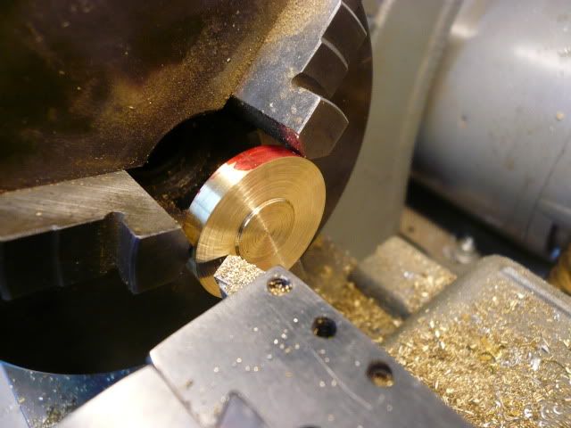
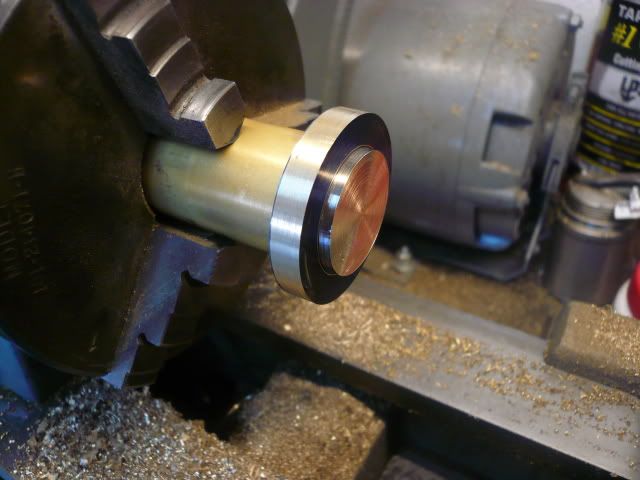
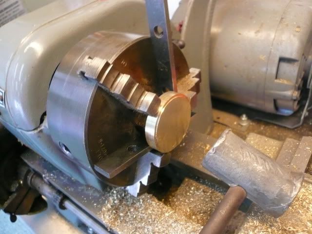
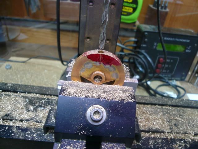
The engine has a front and a rear cylinder head. The front head is pretty straight forward. Turn to diameter and part off. The small depression is just for decoration. Also, it’s hard to see, but before parting off I used the lathe index to mark the bolt circle for the four mounting bolts.
P1040589.jpg


Flip the part over and re-chuck to turn a 1/32” high register for alignment with the cylinder.
P1040591.jpg


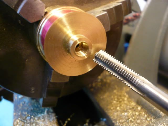
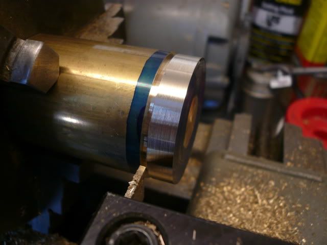
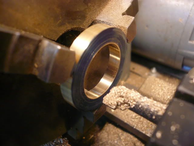
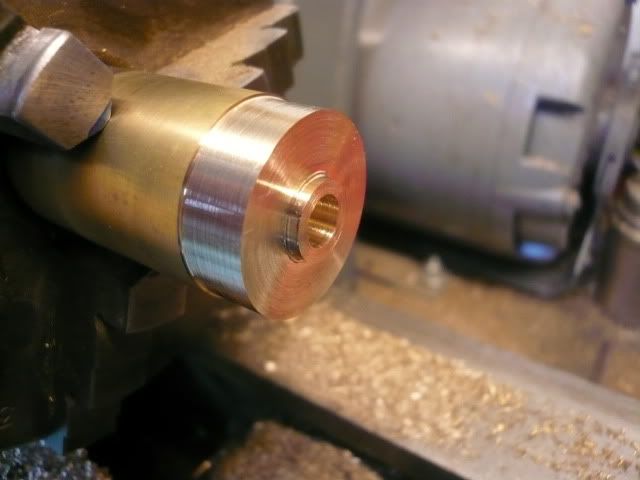
The rear cylinder head is slightly more complicated because the piston rod goes through it and everything needs to be concentric with the cylinder bore. Turn to size, bore 1/8” for the piston rod and drill and tap 1/4-28 for the stuffing gland. Notice I forgot to chamfer the hole before I tapped it. I wouldn’t have that burr if I’d have remembered.
P1040603.jpg


Next ream the 1/8” piston rod hole. This head has a 1/32” high register on the back side just like the front head's. Because alignment is critical, I turned this one to size before parting the head off. Also marked the bolt hole pattern before parting.
P1040606.jpg


After parting, punch, spot and drill the mounting holes. I drilled them to 1/16” and used a piece of pointed 1/16” drill rod as a transfer punch to transfer the holes to the cylinder. After marking the cylinder, you can enlarge the cylinder head holes to final size. This completes the heads.
P1040843.jpg


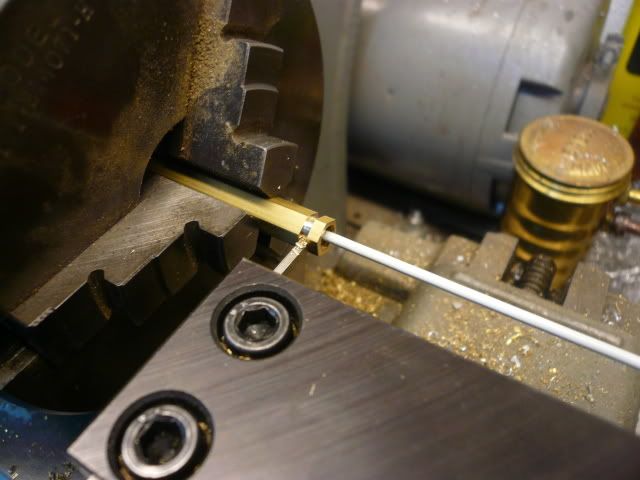
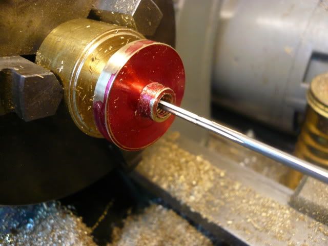
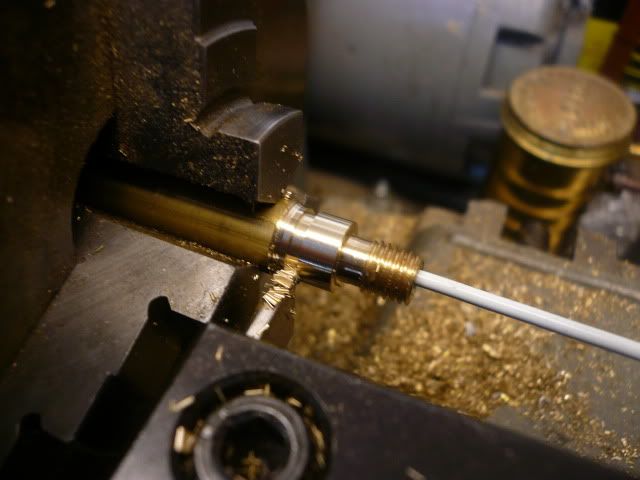
Unlike the steam chest gland, I made the cylinder gland from one piece. That’s because I intend to use Doug Lanam’s design for the cylinder guide and it requires a longer stuffing gland. The extra length you get from cutting the threads with a die will actually be an advantage.

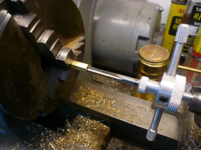
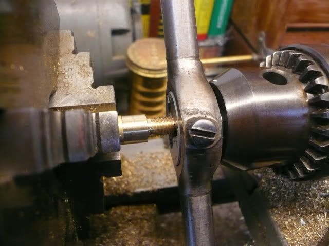
To make the gland, a piece of brass was turned to size, threaded 1/4-28 and bored to 1/8”.
P1040609.jpg


A single point thread would have gotten a lot closer to the shoulder, but in this case it’s not a problem. Because of the die design, the last few threads are not to full depth and were removed before parting.
P1040611.jpg


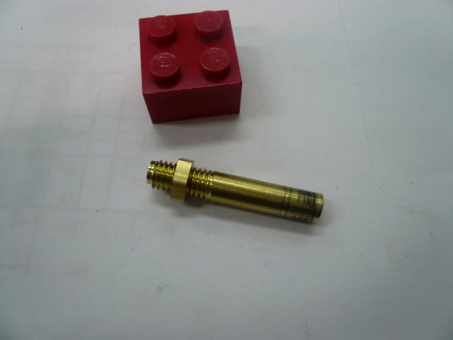
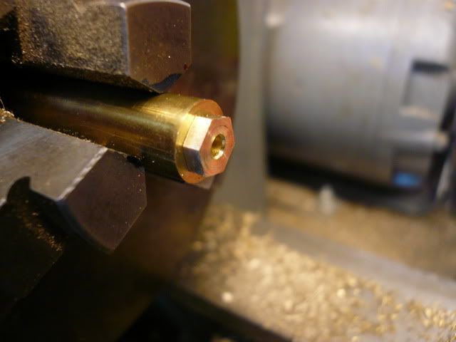
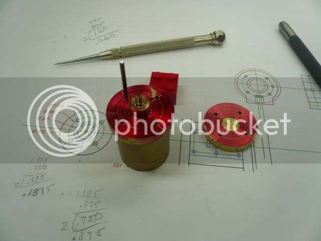
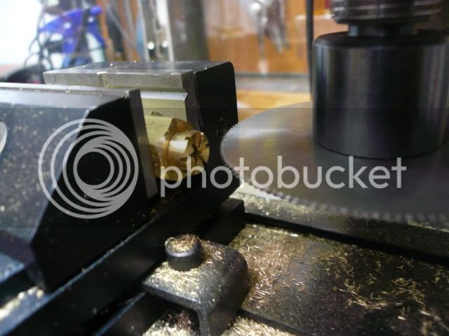
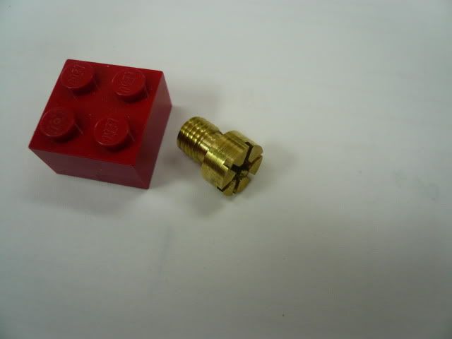
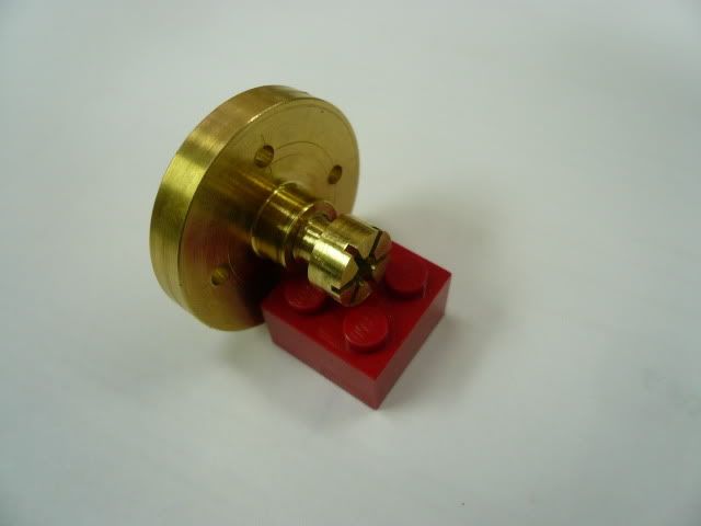
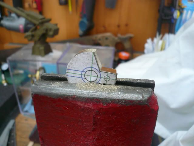
Normally the gland nut would have a hex end or tommy bar holes for adjustment, but because of the design of the crosshead guide, this nut sits down in a tube and neither adjustment method will work. I decided to go with multiple screw slots that (hopefully) can be adjusted by reaching in with a probe or small screw driver. To make the slots, I made an indexer by tapping a piece of hex stock to 1/4-28, installed the gland nut, then cut the slots with a slitting saw. Worked great. Hope the adjustment scheme works as well.
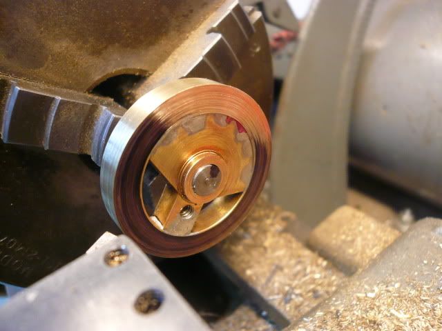
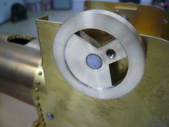
P1040639.jpg


Here’s the finished gland nut,
P1050174.jpg


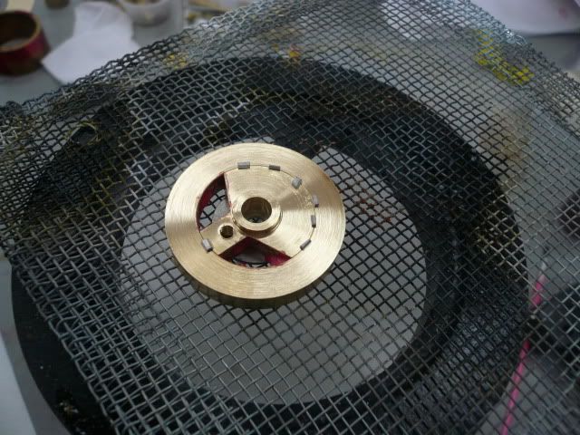
And in the cylinder head.
P1050181.jpg


That's it for now.
Dennis

 
Nice work Den'. I like the gland adjuster slots, hope that they work out for you. You are also correct about the 'initial' being out of sight on the valve cover. The front cylinder cover would be a much better place for such an embellishment. I'm anxious to see you fabricate the tube trunk guide for the crosshead. Keep up the great work and thanks for sharing with all of us.

BC1
Jim
 
Jim,
I'm hoping to get to the crosshead guide next week...no promises though.

Crank

The crank is 1 3/8” OD, 3/16” thick brass. It’s made in two pieces to make it easier to neatly remove two triangular sections.

I started by turning a 1 3/8” OD x 3/16” disc.
P1050025.jpg


then bored the center to 1” to make a ring.
P1050038.jpg


and fit the ring to a piece of 1” stock. The two parts will be soldered together, so the fit is loose, but not sloppy. How’s that for really pinning the fit down? :big:
P1050053.jpg


Fabricate the center section by drilling a “D” size center hole (later to be reamed to 1/4") and turning a 1/16” high boss on the face.
P1050056.jpg


Part or saw off a 1/4" section and reverse in the chuck to face the back side. I used a couple of parallels to help with alignment. Of course they’re removed before turning. Alignment and concentricity aren’t critical here because everything will be trued up after solder, but close is better.
P1050027.jpg


After facing the back side, lay out the crank. I rubber cemented a pattern on. Saw off the two triangles and drill and tap the hole for the crank pin.
P1050059.jpg


Then assemble for solder. I used soft solder and aligned things so the two pieces are flush on the back side and the center piece is inset by 1/32” on the front.
P1050063.jpg


After solder, drill and tap the rim for a 6-32 set screw.
P1050072.jpg


Ream the center hole to 1/4" and turn a 1/4" snug fitting mandrel. Mount the crank on the mandrel using the set screw. From this point on, the mandrel shouldn’t be removed from the lathe chuck. Turn the outer rim true, face the front side, reverse the crank on the mandrel and face the back side
P1050081.jpg


to complete the crank.
P1050088.jpg


I wanted the 1/32” inset because I’m thinking I’m going to paint the center of the crank and the inset will help define the line. Rudy did his flush.

Dennis


Dennis
In the pix where You solder the cylinder between the two stones what is that screen
material the cylinder lays on and the pins stick in?

By the way that old plumbing stuff You found the "graphite packing " some one told me
it is worth like gold. Supposedly it is not made any more because of the asbestos. I still
have a roll of it from the 1960s. I don't know if it true
Hilmar
 
Oh my Dennis, you are way out in front of the embellishment curve here. I am glad to see that I am not the only person that thinks the surfaces being flush appears horrible. The recess will indeed define those surfaces and give a more scale like appearance (but you know that already) ;D

Looking GREAT!!!


BC1
Jim
 
Thanks, Jim.

Hilmar,
The solder surface you referred to is a honeycomb ceramic block. I picked mine up at a swap meet, but they're available on-line. Should be around $10. Their claim to fame is a flat, stable surface that you can stick positioning pins into. Also, supposed to have good heat reflectivity. I haven't used mine much yet, but like it so far.
Dennis
 
Back
Top