Building Rudy's Steam Tractor

Home Model Engine Machinist Forum

Help Support Home Model Engine Machinist Forum:

This site may earn a commission from merchant affiliate links, including eBay, Amazon, and others.
One of my next project is a tractor...I'm learning a lot eyeing yours work progress....!! Thanks for sharing! Great job
Cheers
Paolo
 
First, Paolo thanks for the comment. It's good to know someone's following along.

Bearing Blocks

The horn plates are made from 0.042” brass. They bolt to the fire box wrapper and support the power train axles.

P1030910.jpg


This cheapie punch from Harbor Freight worked very well for getting round precisely placed holes for the axle shafts. It’s a handy tool to have around.

P1030936-1.jpg


The axle shafts run through six bearing blocks that are mounted to the horn plates. The bearing blocks are 5/8” x 5/8” x 3/16”. Rudy used aluminum blocks with small inset bronze bushings. But life is short, so I’m going with brass blocks with reamed holes for the bearing surface. The axles will be ¼” drill rod. Rudy suggests turning the axles between centers, but again, life is short.

I milled the blocks as a group.

P1030944.jpg


P1030948.jpg


Since the blocks are identical and diagonally symmetrical, I decided to build this variation of a vise stop I saw on the Sherline site (http://www.sherline.com/tips.htm).

P1030953.jpg


It worked great and was well worth making. Also note the packing peanut holding the parallels in place. I don’t know where I read that tip, but it works very well. No worries about drilling into it.

P1030959.jpg


The finished bearing blocks with a couple of spares.

P1030964.jpg


The bearings eventually get fastened to the horn plates but before doing that, I did a trial fit. Turns out that was a good idea because I had to do a little trimming on one of the sheet metal parts.

P1030975.jpg


After everything fit, I spotted the bearings using a piece of ¼” drill rod and line bored for two mounting rivets.

P1030976.jpg


And here are the horn plates with mounted bearing blocks. The half width piece is a nut plate that the idler shaft bolts into.

P1030978.jpg


Regards,
Dennis
 
Gear Train

Other builders of Rudy’s Steam Tractor have mentioned that the speed of his tractor seemed too high. To slow it down, I picked gears that give a crankshaft to wheel ratio of 50.6:1 which means my tractor should move at a little less than half the speed of Rudy’s. One set of gears was added to the train to get the lower speed.

All gears are 48 pitch, 14.5 degree pressure angle, brass with an 1/8” face. The source was SDP-SI Drive Components, www.sdp-si.com.

Even with all the choices of gears, it ended up that every gear with the exception of the countershaft pinion required some sort of modification.

Name Teeth Pitch Dia. Required Modification:

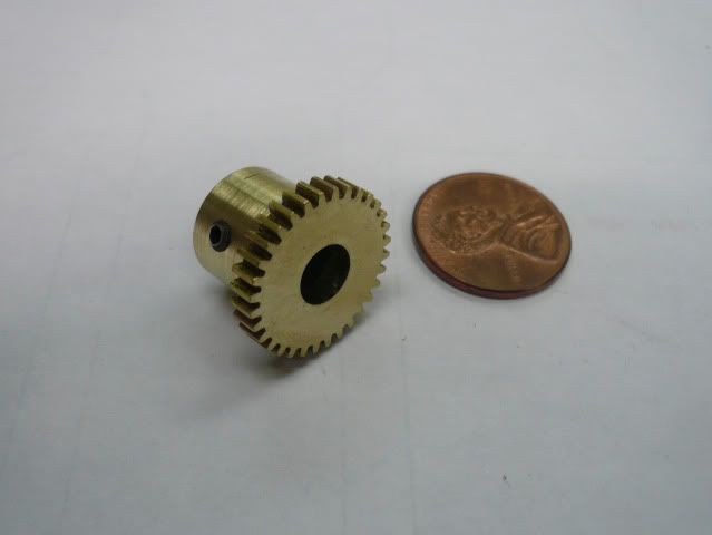
Crankshaft Pinion 32 0.667 Add hub & enlarge hole
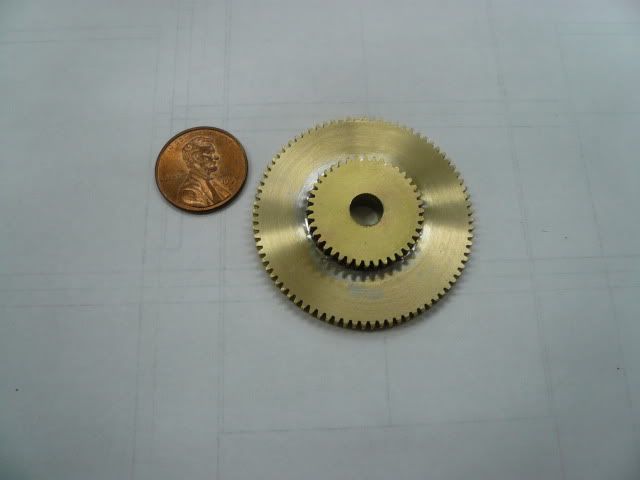
Idler
(Compound) 80 1.667 Remove hub
(Compound) 40 0.813 Enlarge hole
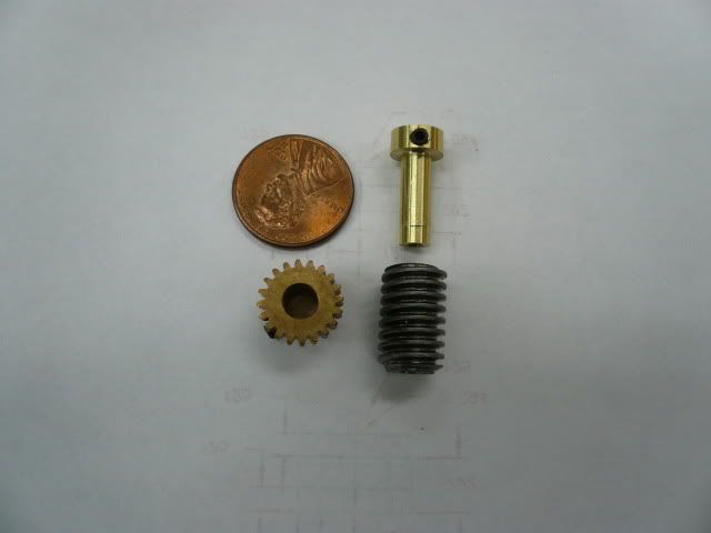
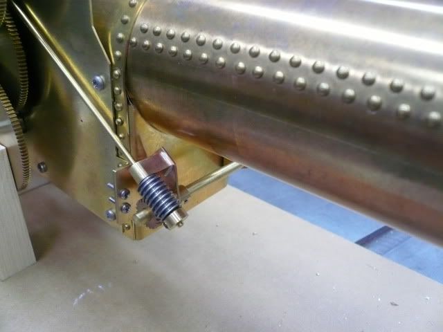
Countershaft
(Compound) 108 2.250 Shorten hub, add setscrews
(Compound) 16 0.333 No mod required
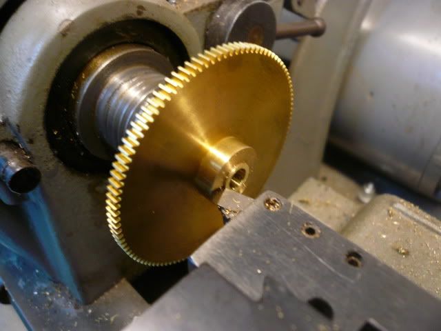
Bull Gear 120 2.500 Reduce hole/hub dia. Setscrews

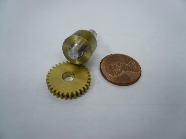
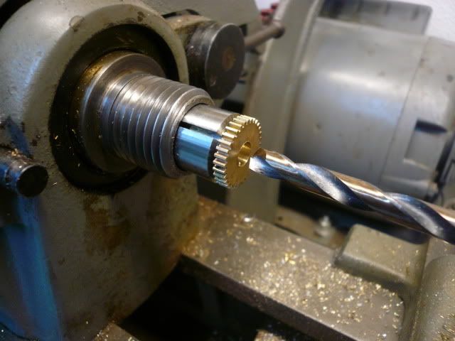
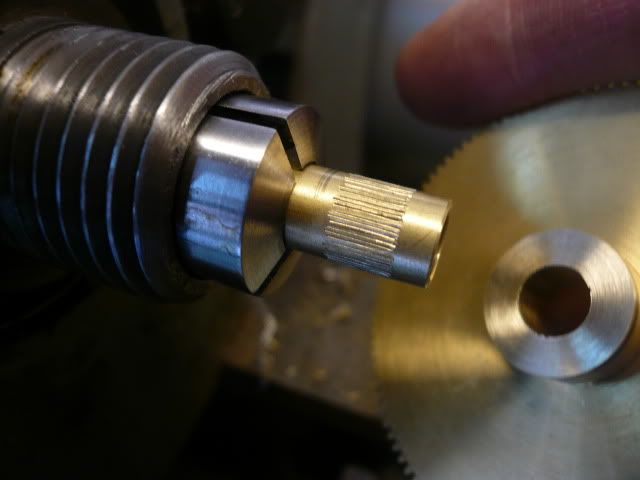
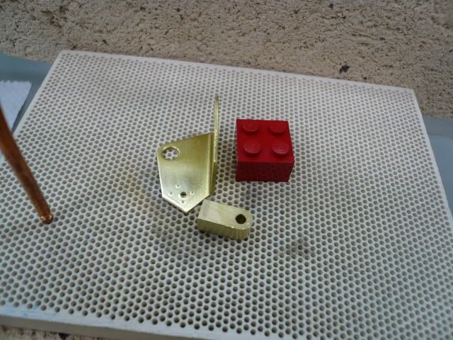
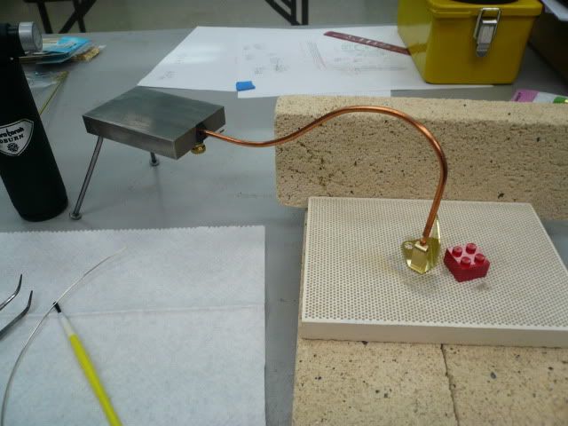
To add a hub to the crankshaft pinion, I made the hub, then turned an aluminum mandrel with a step to match the hub and pinion ID’s.

P1030890.jpg


Soft soldered the two together, removed the aluminum mandrel, then drilled and reamed to 1/4".

P1030893.jpg


P1030894.jpg


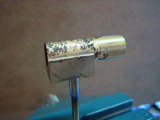
The idler compound gear was done using the same aluminum mandrel. I was concerned about getting solder in the smaller gear’s teeth, so I put the solder between the gears first.

P1030901.jpg


It was a good plan, but poorly executed. I used too much solder and was pushing down on the top gear as the joint heated. When the solder melted the gear dropped into place, squirting solder out the edge. Luckily it only got into a few of the smaller gear’s teeth, but it made a mess of the large gear face. Cleanup involved picking the solder out of the teeth with dental tools and chucking the gear in the lathe and refacing it. Lesson learned: less solder, more patience.

The whole episode reminded me of a comment Rudy Kouhoupt makes in one of his videos about the best way of cleaning up a mess is to not make it in the first place.

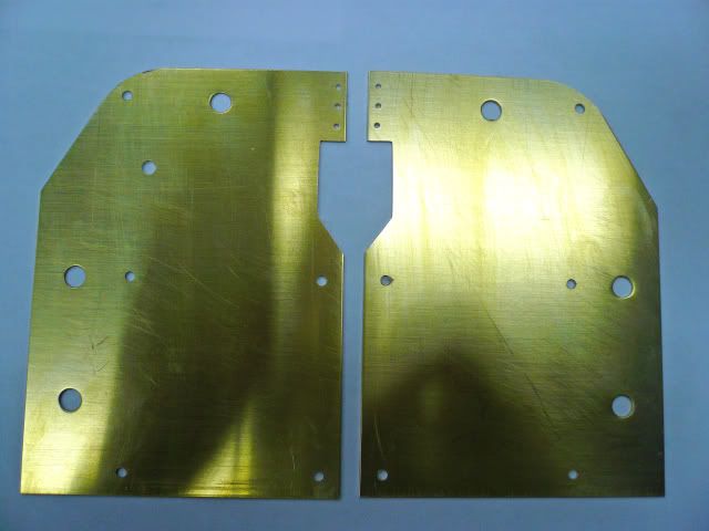
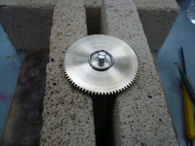
The gear cleaned up fairly well and is fully functional, but you can still see some of the solder residue. Fortunately it will be hidden by the horn plate.
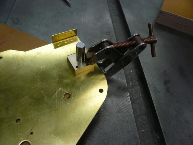
P1030902.jpg


The larger gears came with a 5/16” bore that needed to be reduced to 1/4". This was done by turning a bushing, locktiting it into place and then trimming after the loctite cured..

P1030907.jpg


P1030929.jpg


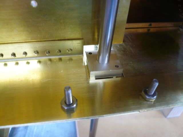
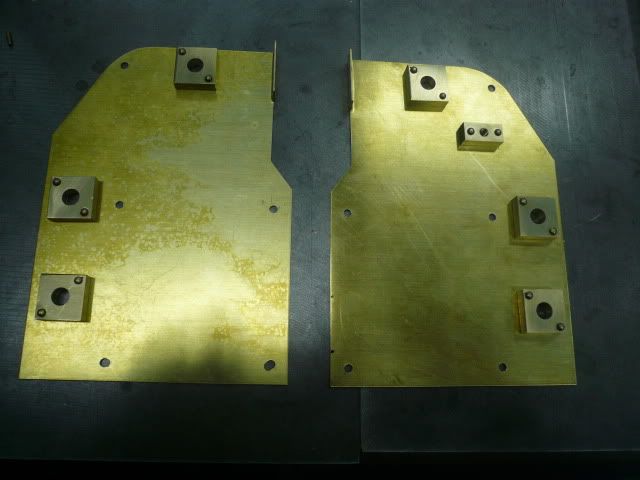
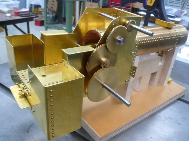
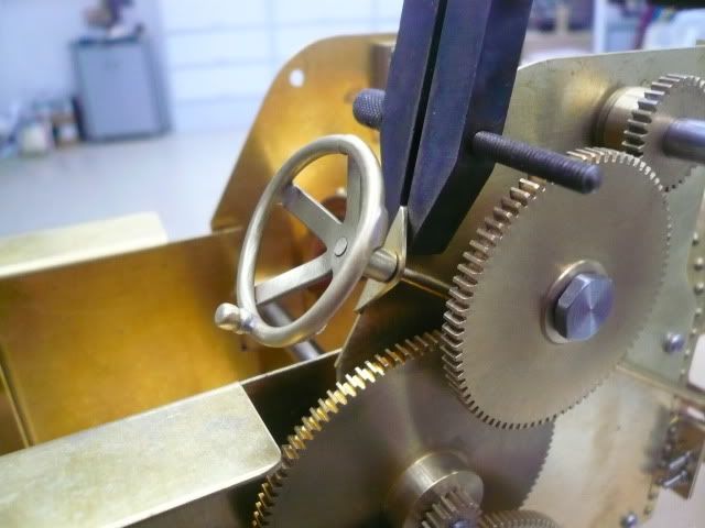
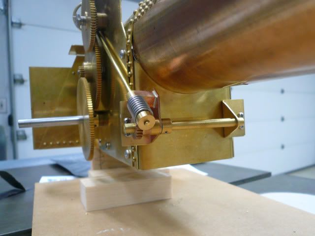
Once modified, the gears meshed nicely and everything fit where it’s supposed to.

P1030967.jpg


Dennis
 
Dennis, you are killing me here! Terrific looking work and I see why you are not a plumber :big:
If I may inquire, what was the cost (more or less) of that gear package from SDP? I had cost out a gearset from Boston Gears and am still cleaning up the mess I made in my drawers when I got the price quote th_confused0052 Thank you also for the marvelous camera work documenting your fantastic work.

BC1

**added note**
Never mind about the cost, I did the research and SDP is cheaper than BG.

BC1
 
Dennis,

Beautiful work. :bow: :bow: :bow:

Best Regards
Bob
 

Very nice work, it looks great.

Nice tooling too!
 
Nice work,thanks for shareing.

Ian (seagar) :bow: :bow: :bow:
 
Thanks for the comments guys.

Jeez BearCar, here I'd just managed to get over the cost of the gears and you come along and re-open the wound! ;D

Yep they're pricey. I had figured out a set that was considerably cheaper, but I would have had to compromise on the gear ratio plus use a combination of pressed steel and plastic gears. When the time came to push the order button I just couldn't do it. You've got to admit these wide face brass gears look good.

You can bet that since I ordered these, no appliance, toy or tool gets thrown away without me eyeballing it for any gears!

Regards,
Dennis
 
Nice job...please post more...!!! th_wwp
Paolo
 
Yeah Denny, they be good and pricey, that is a fact. I truly DO admire your style :bow: for not going the low road and cheaping out on such a fine looking project. Those gears are worth every pound. ;D
Cheers

BC1
Jim


Steering

The steering wheel is pretty much per Rudy’s plan.

P1030996.jpg


The rim is formed from 3/32” brass rod. It’s over bent around a mandrel, then cut with a jewelers saw.

P1030992.jpg


The spokes are cut from 0.032” brass sheet with a jewelers saw. I used a machinist vise and a couple of 1/4" spacers to get the spokes dished evenly.

P1030999.jpg


This was my first “production” silver solder part. I used silver solder because the hub and steering knob need to be soldered to the wheel too and I couldn’t see how to do them all at once. Anyway, I needed to get over my fear of silver solder because the engine and boiler are coming up and they require a lot of it.

Here’s my setup. Thanks to “ghart3” for the holddown critter idea. It works great!

P1040009.jpg


The center hub was then soft soldered to the spokes leaving the steering knob as the last item.

P1040007.jpg


The nubbin is 1/32”. This is the smallest part I’ve ever fabricated. I now have a whole new appreciation for the miniature work some of you guys do. Here’s the soldering set-up. The white is water soaked rag to keep the center hub from de-soldering. (I should have mentioned that I drilled the 1/32” knob hole in the rim prior to soldering the spokes on.)

P1040017.jpg


It all looks pretty calm in the photo, but I forgot about making sure that things can’t move during soldering. Mid-way through, the flux pushed the knob up and out of the hole. Needless to say things are anything but calm when you’ve got a torch in one hand, a tweezers in the other and you’re trying to put a nub into a 1/32” hole while your hands are shaking at 1/8” plus! Anyway, all’s well that ends well.

P1040018.jpg


Regards,

Dennis


very nice work there . i like the hold down thingy. thank you for showing us a wonderful build.
 
Looking GREAT Dennis!

Working on that scale is far beyond my own skills.
That makes it even better to see it being done.

Keep the updates coming!

Rick
 
Dennis:

I'm still following with great interest, and it's looking damned fine! My copy of the book just arrived from Village Press... between the book and your thread, I'll be all set. Sadly (for me) you've set the bar rather high for fit and finish! Keep up the great work. :bow:

Cheers, Joe
 
Guys,

Thanks for the comments. Joe, I hope you'll post your progress.

Steering (cont’d)

The steering pinion is a 20 tooth gear with a 0.417” pitch diameter. The steering worm pitch diameter is 0.333”. Both were purchased from www.sdp-si.com. The worm gear ID is 3/16” so it needs to be sleeved to fit the 3/32” steering shaft. The sleeve also provides a place for a set screw so the steering wheel and shaft can be removed. I used loctite to hold the sleeve in the worm gear.

P1040107.jpg


The right steering bracket uses a 1/4" square post to hold the steering shaft and worm in position. The post has to be mounted at just the right angle so the gears mesh smoothly. I clamped it in place, marked it, and then silver soldered it. I think it could just as well be soft soldered, but I’m trying to build my silver solder confidence before I get to the engine and boiler. The following pictures show the process. The four prick punch marks provide a small gap between the parts for solder flow.

P1040123.jpg


I’ve learned the hard way that with silver solder things need to be held in place or the boiling flux will surely move them.

P1040126.jpg


Solder and flux in position. I’m soldering with a basic hardware store propane torch (not the little butane one visible in the above photo).

P1040129.jpg


Part after soldering. (I’m hoping experienced silver solderers will chime in here. Does the blackened flux mean I held the heat on too long and if so, is it detrimental to the joint?)

P1040130.jpg


This is the part after one hour in citric acid pickle and brushed with a toothbrush.

P1040136.jpg


Part after 0000 steel wool buff. I’m happy with it. My second silver soldered part!!

P1040140.jpg


Here it is mounted on the tractor. The Phillips head screws are only temporary.

P1040199.jpg


The last steering part is a sheet metal bracket to hold the upper steering post. It’s positioned to match the angle of the 1/4” post on the lower bracket and then riveted to the horn plate. I’ve just clamped and marked it for now and will rivet it the next time I take off the horn plate.

P1040200.jpg


Here’s the completed steering assembly showing the chain shaft & spacers. The steering chains will be fastened to the shaft using two 2-56 screws.

P1040327-1.jpg


Dennis
 
Dennis, looking real good. Your doing a nice job.

On the hold down your using for silver soldering, copper might not be the best choice. Not only does it conduct heat good but silver solder loves sticking to copper. Stainless steel that has been heavily oxidized from over heating works good especially if it has to be real close to the joint being soldered (brazed)
 
Gary,

You're right about the copper. Note I did neck it down to try and minimize heat conduction but i've got to admit I never even considered the possibility of soldering it to my part. It was a case of using what I had until I found the right thing. Your tip on using oxidized stainless is a good one. Also have been told to try broken titanium bike spokes. Hard to find though.

I've just got to say thank you again for posting photos of your hold down critters. They're a great idea and unbelievably handy. If you haven't seen Gary's, they'rehere. He's a little more imaginative than I am.

Dennis
 
4156df said:
Part after soldering. (I’m hoping experienced silver solderers will chime in here. Does the blackened flux mean I held the heat on too long and if so, is it detrimental to the joint?)

Dennis, firstly, what a beautiful job you are doing :bow: your "sheet metal" work is amazing!

In my silver soldering experience, I don't get blackening as in your photo. Here is a picture of a cylinder that I did recently:

IMG_6725.jpg


The parts are brass and were actually still hot when the picture was taken. I too use citric acid for pickle with results just like yours.

Did you use any abrasive paper on the parts before soldering? Inedequate cleaning of brass dust and abrasive particles can contaminate work. Sometimes I even wash parts with hand cleaner or soap first to be sure of no oil or grease. You should only need to heat the part long enough for the solder to flow, then maybe a few seconds more, but that is it, there is no need to make the parts any hotter.

I have heard of other people using punch marks to create a gap for the silver as well, but I don't. Unless you have a press fit, the silver will find its way into most seams.

I can't wait to watch the rest of your build ;D
 
No words Dennis!! I'm admiring your nice job!! jthulin ,as I learned over my skin, We have to use citric acid for pickle before and after silver soldering for having great results...believe me!!
Cheers Paolo
 
Jeff,
Thanks for the input. I've been doing some practicing and you're right about not getting the heat off quick enough. I thought I had to stay on the joint longer to insure the solder flowed everywhere. Not so. As you said, just a few seconds after first flow and it's done.

Paolo,
Your posts on soldering your boiler have really been helpful. You've saved me from a lot of problems.

Regards,
Dennis
 
Back
Top