Another Jan Ridder Flame Engine build

Home Model Engine Machinist Forum

Help Support Home Model Engine Machinist Forum:

This site may earn a commission from merchant affiliate links, including eBay, Amazon, and others.

huse0054

Active Member
Joined
Nov 17, 2010
Messages
31
Reaction score
0
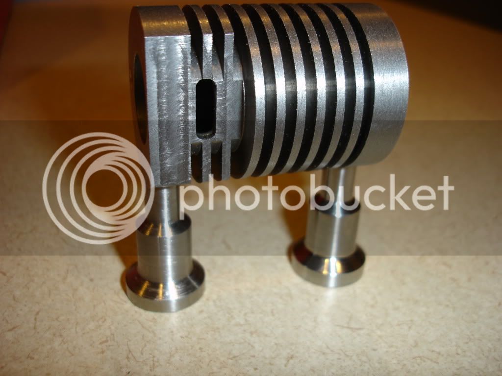
Hi there, I am in the process of building a Jan Ridder internal valve flame engine, why? Because they are insanely intriguing and amazing engines!!!! Now I have never seen one in person, only videos on youtube so I hope that mine will actually work and that it turns out as good as some I have seen. I have read through most every flame engine post on this forum and thought I should go for it. I also wanted to document the build so others can see how I did it and I will try to provide as much detail as possible about the steps I went through and the problems I encountered.

As some background, I enjoy creating stuff from plans and I don't have a creative bone in my body but I am very meticulous and can be somewhat of a perfectionist and I am OK with that. It should also be noted I have never machined anything before and I own no machining equipment. I do not know the correct machining vernacular and how some tools work etc....., and it will be glaringly obvious in my build posts that I am a complete novice, but I am learning and that is the whole goal of building this engine. I am also having a blast doing it!

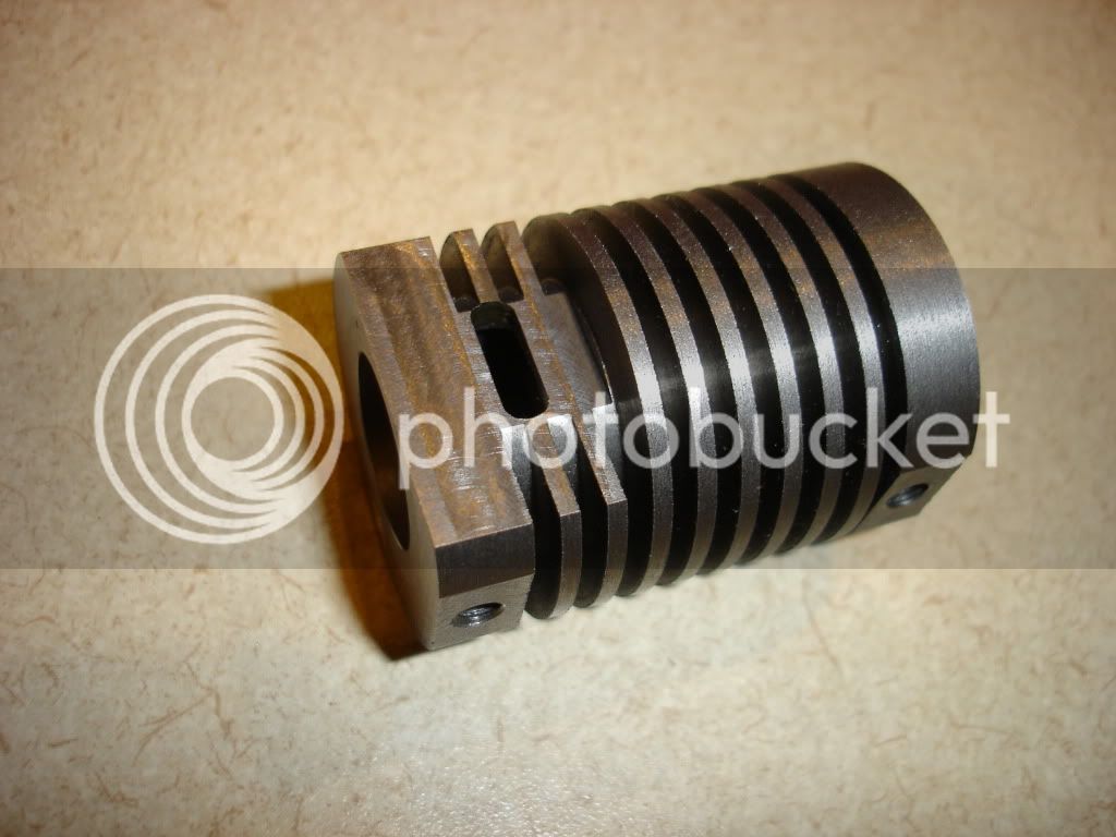
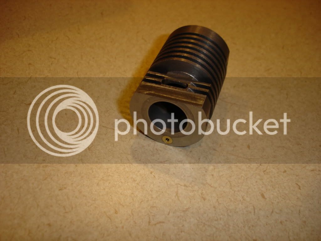
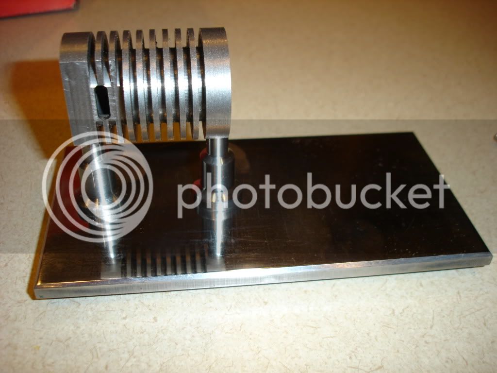
I know this thread is useless without pictures and one problem is that I am about halfway done with the engine and have not taken any pictures yet. I will take pictures of the completed parts thusfar and incorporate those into the step by step posts and will take pictures of the process going forward.


And one other thing, my wife's father and grandfather own a machine shop and her grandfather will be helping me in this build :) should be noted he has no experience in the model engine world.

Thanks again for this fantastic website and talk to you soon.
 
Welcome to the site...will be looking forward to seeing the pics, even of the already completed parts.

Bill
 
Like I mentioned before I am about halfway done but here are some of the parts that have been completed, pre polish.

-First Started with turning the 4 bearing support columns on the lathe out of 1/4" stainless round, we then drilled and through tapped for 6-32 stainless Hex bolts. 3 went swimmingly however the tap broke in the 4th one so we had to make another one. They were all rough cut on the lathe and we ground the 4 down on the surface grinder together by bolting them to a piece of scrap steel that was ground on both sides. Then used the depth micrometer to get all 4 to the exact plan height.

DSC00106.JPG
 
Next were the cylinder support columns that were turned out of 1/2" SS round. They were then drilled completely through to accommodate 10-24 bolts from the bottom that will go through the base plate and then screw into the cylinder. We ground the columns to the finished height on the surface grinder as well

DSC00109.jpg


The cylinder was next, we made it out of cast iron that was roughed to size then finished to final size. To add the fins we had to make a 2mm tool and that worked out fantastic other than the fact we both screwed up on the measurement on the lathe, the 6mm depth actually turned out to be only 3mm, apparently there is a difference between the diameter and radius indicator on the DRO! :) We didn't figure this out till after we had completed the entire cylinder. The next day we made up a mandrel and used that to turn the fins to the correct 6mm depth, I will try and get a picture of the mandrel we created as I will probably use it again for final sanding and polishing of the cylinder.

After the fins were completed we used a boring bar to complete the cylinder hole. We then used the surface grinder again to get both ends perpendicular to the bore and parallel to each other while at the same time creating the finish length of the piece. Then onto the mill to grind the flame port, mill the 1mm flats for the support columns and drill and tap for 10-24 bolts. We then used a reamer to create the valve rod hole.
DSC00105.jpg


Next step was to turn the bushings for the valve rod and press them into the reamed holes. Then onto lapping the cylinder. We created another mandrel and used lapping compound and some diamond lapping paste to smooth out the bore. It worked great and opened up the ID slightly but not an issue as we are planning on making the valves and piston to fit.
DSC00104.jpg
 
I am going to use 1/4" stainless for the base with a milled chamfer that may be removed for flat 90 degree sides that can be polished to a mirror finish. I will wait to decide on that. Getting the stainless flat was a slight challenge, we used the large rotary surface grinder (Blanchard I think) but the stainless was getting too hot and it created a bow in the middle as it was being held by a large vice. We then decided to weld a piece of scrap steel to the bottom of the stainless and regrind on the smaller manual surface grinder. That worked fantastic and the top was as smooth as could be. I then proceeded to sand and buff the top but something happened and it created a ton of scratches. I will have to regrind and try again. I want to try and get that mirror finish without the scratches. I must have done something wrong.
DSC00110.jpg


See how bad it looks closeup!
DSC00111.jpg
 
OK, onto the flywheel. We made this out of a chunk of 3" diameter brass. The 1mm hub on each side was added and then it was turned to the finished diameter and thickness on the lathe. The rest of it was milled using the rotary table. 5mm deep recesses on each side then a 1/2 inch end mill and 6 60 degree rotations on the rotary table to create the holes, we also added a slight chamfer to each hole. We then drilled and tapped the set screw hole and part complete! If I did it over I would sand and polish the mill marks out of the inside diameter recesses before drilling the 6 holes.
DSC00113.jpg
 
Created this little piece out of brass in a hurry and I am not too fond of it. Will probably remake at some point.
DSC00115.jpg
 
Bearing supports out of 1/4" brass. Fairly simply and didn't stray too far from the plans, used the mill simply cut bearing holes to fit. Still needs some sanding and polishing. This stuff is like hot butter compared to stainless, scratches and dents galore!


DSC00114.jpg
 
That's a good start on what should be a fine engine when you've got it done there, huse0054.

I've found that a good portion of the time it takes to build an engine is spent getting the finish to pass muster. I spend a lot of time scraping my engine pieces across a piece of emery cloth.
 
Thanks Dennis, I plan on spending many hours sanding and polishing once it is running. From what I have read many people have not been able to get theirs running and I figured I can shine everything up to "show" quality at that point. Thanks again and I am learning a ton and having fun doing it!

 
Well I will try to get caught up to "live" status. Everything prior to now was created over the last month.

We started on the crankshaft and are making it out of a scrap piece of 1.5" diameter stainless steel

Roughed the shaft to size on the lathe
DSC00081.jpg


Finished shaft diameter to ID of flywheel and bearings
DSC00083-1.jpg


Created a shoulder to ride on the bearing and finished crank diameter and thickness. We then used a hacksaw to remove the piece from the rest of the bar stock, flipped the piece around, re-chucked it and faced it off.
DSC00091-1.jpg


Finished with the turning on this piece, now we need to remove some material to make it look good and to create the pin for the connecting rod.
DSC00108.jpg

DSC00107.jpg
 
OK, so have the engine in the rough finished stage, meaning I have all the parts made but it is not polished etc.. I will wait until it actually runs until I get it looking nice.

- I am in the trouble shooting phase per Jan's website and I am just trying to get the flywheel to spin for 1.5 to 2 minutes and it isn't happening. When it is bolted down it spins for 15 seconds and when I unbolt it and rest it on the base it spins for 30-40 seconds depending on how much muscle I put into it :)

Any thoughts?

I have little experience with bearings but how tight of a fit should they be in the support? I am wondering if they were deformed when I inserted them. Should the flywheel hub be touching the inside bearing race? If they are touching would that increase friction?

For those who have running engines are there special bearings that are needed?

It feels like it is spinning smoothly and I can't believe I am so far away from the 1.5 to 2 minutes Jan recommends.


Mine doesn't spin that long either. I can't remember how long it went but it was no where near what Jan recommends.

Bolted vs. unbolted--sounds like something is getting a bit out of line. When I set mine up I bolted down the cyl and then the bearing support nearest the connecting rod. Got that lined up and spinning nice. Then tweaked the other bearing support until it spun the best.

You can get the bearing pockets too small where they will squish the bearing. Mine were actually a bit too big and I had to use a punch to prick the walls a bit to make for a tighter fit. I would say loose is better than too tight (just get it so the outer race doesn't spin) as you want the least friction possible.

Yes the flywheel hub should touch the bearing inner races--that's what keeps it inline. There's nothing special about the bearings. Remove the seals (and toss them), flush out all the grease, and use a few drops of light oil instead (I use sewing machine oil).

Try and get it to run...if it ain't broke--don't fix it.

 
Thanks, for the info, I will try again, and I think one of them was too tight, I tried spinning it with a pen and it feels rough and a makes a grinding sound. I have new ones on order and will try opening the hole up slightly.
 
I don't think mine spins over for very long on it's own either, but it runs ok "under flame"!

Vic.
 
Well I had it running for the first time tonight :). (If I can get it running continuously I will post a vid) It only sustained itself for a max of 45 seconds and I could feel the "power" increase while I was moving the flame around. I feel I am so close to getting a sustained run, however when I did get it to run, although briefly, it was directly after I dumped a bunch of graphite into the flame port. Any suggestions on next steps?

I am getting good suction when doing the trouble shooting so would that mean the graphite is reducing the friction, thus I should lap the piston and cylinder more to create more clearance?

I also am getting a brown residue on the flame port and cylinder where the flame is hitting, it easily wipes off with a paper towel and some cleaner, Is this normal? I am using denatured alcohol, a fiberglass wick and a burner made out of aluminum.


On one of Jan's videos it shows graphite being used as the engine is assembled before a run. I've tried it and I'm sure it helps. I wouldn't use any other kind of lubricant though, particularly liquids.

Vic.
 
Thanks and I will give that a go, the spirits/denatured alcohol are newly bought from the local hardware store. Maybe I will try getting some new stuff.


Latest posts

Back
Top