90 degree V-twin engine

Home Model Engine Machinist Forum

Help Support Home Model Engine Machinist Forum:

This site may earn a commission from merchant affiliate links, including eBay, Amazon, and others.
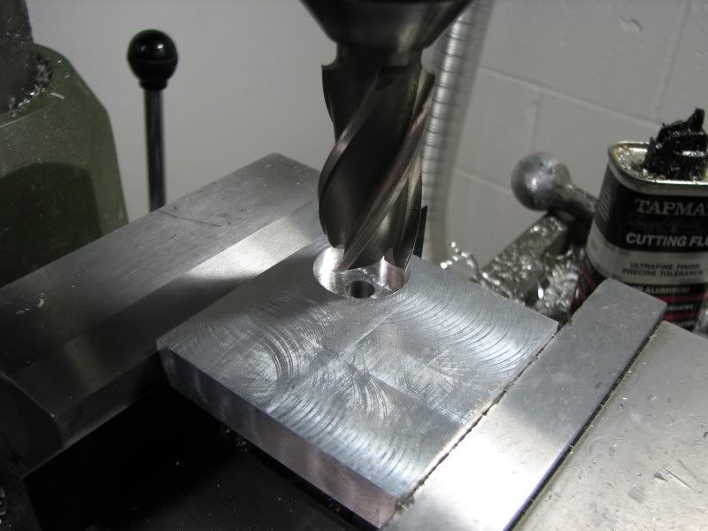
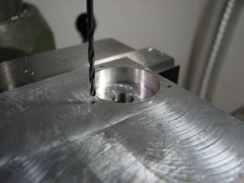
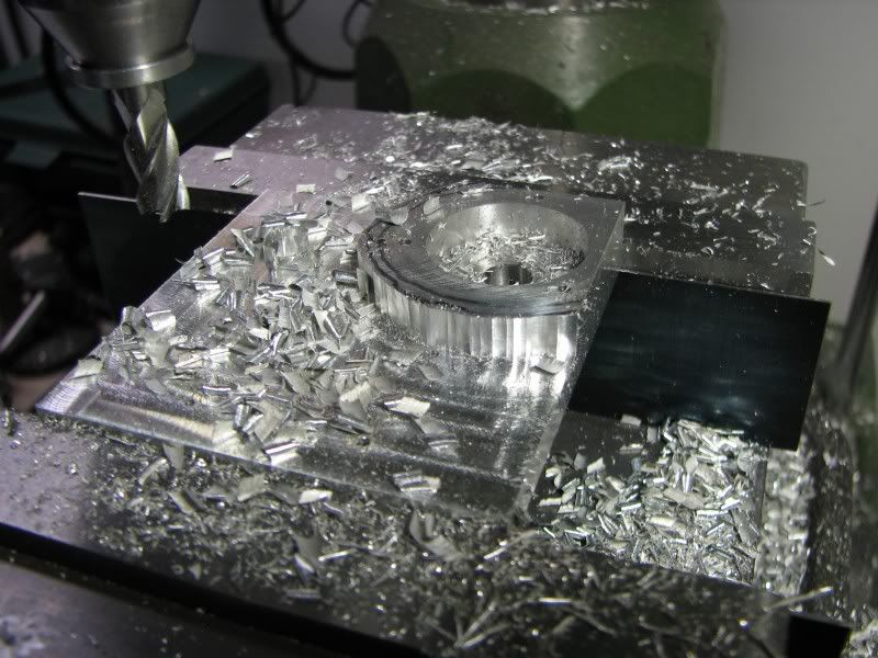
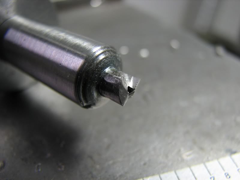
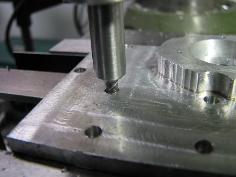
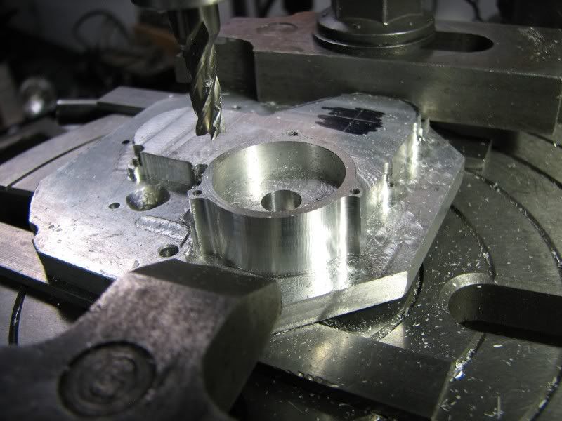
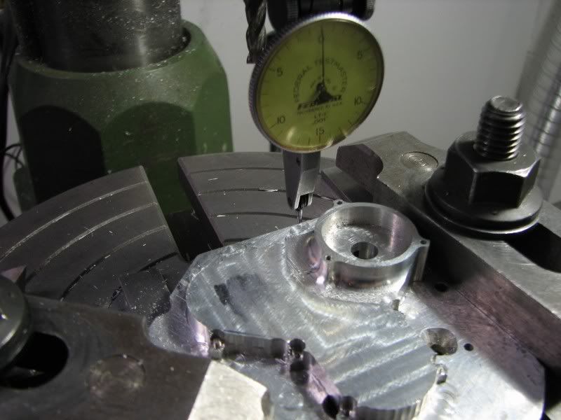
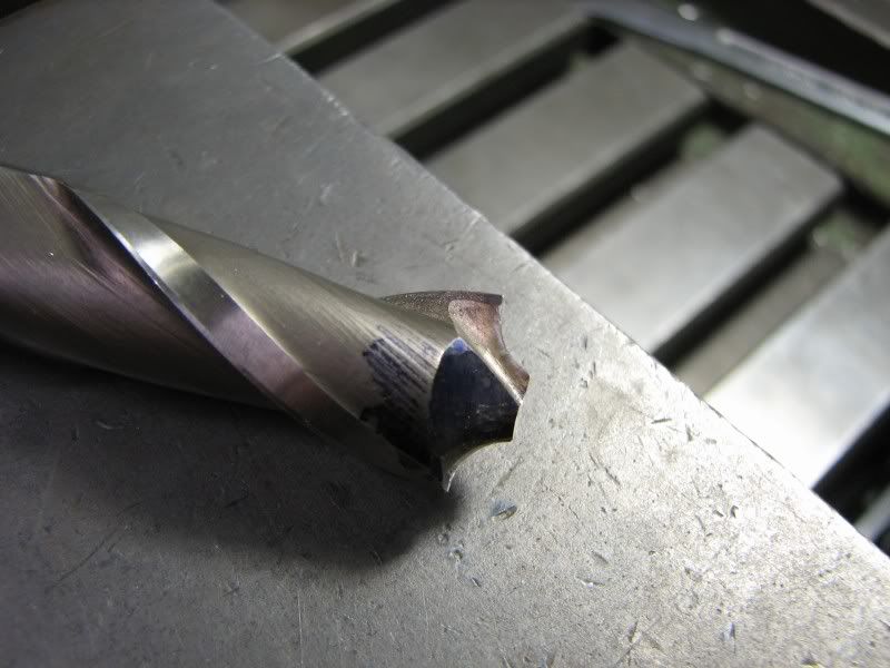
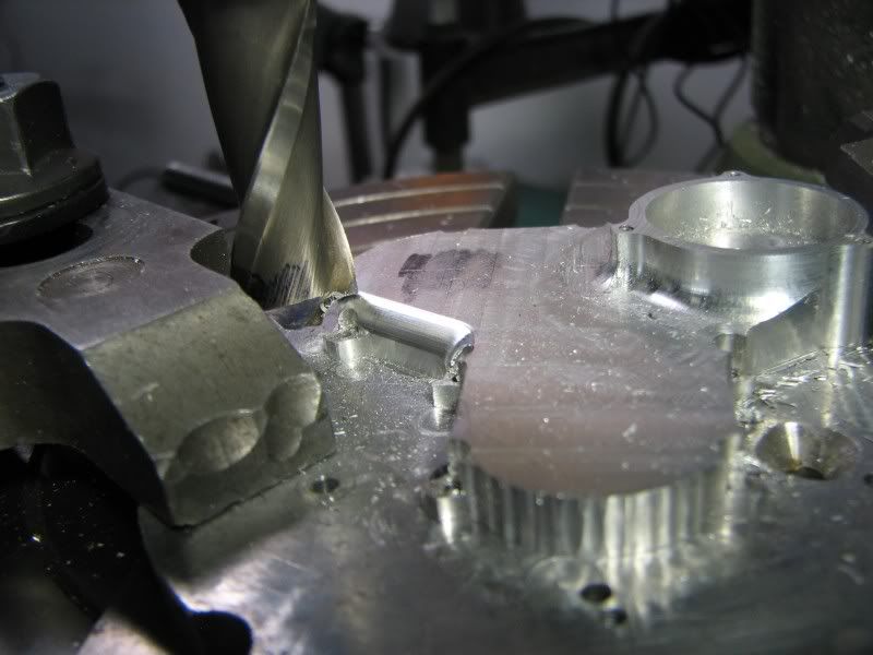
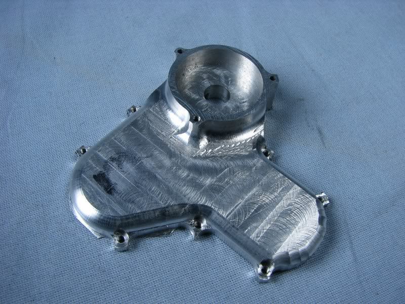
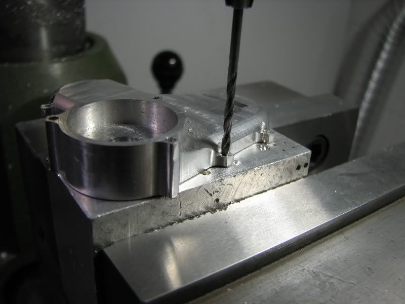
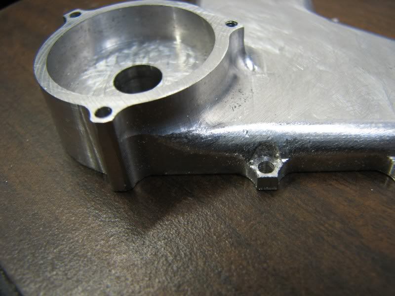
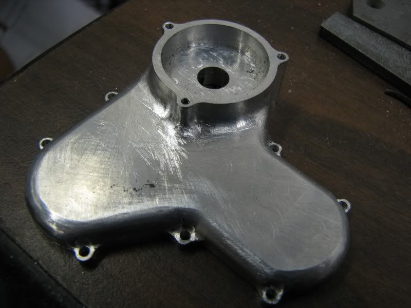
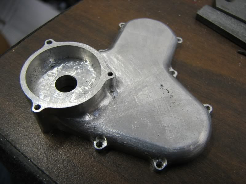
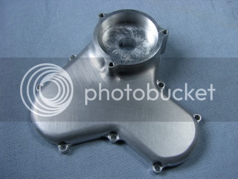
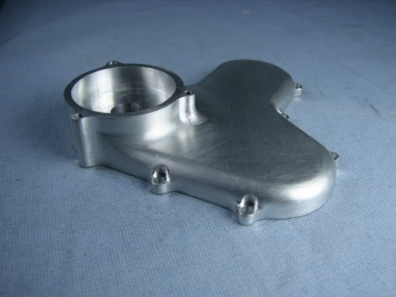
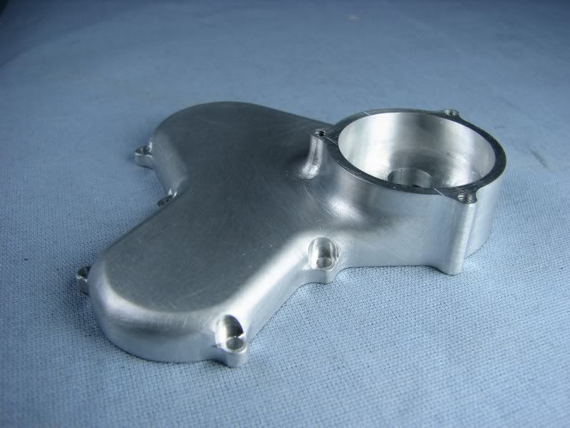
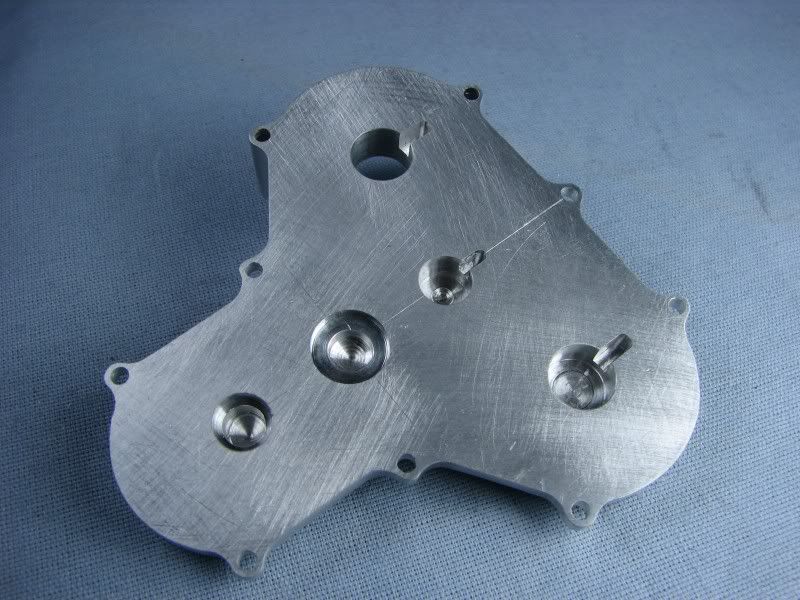
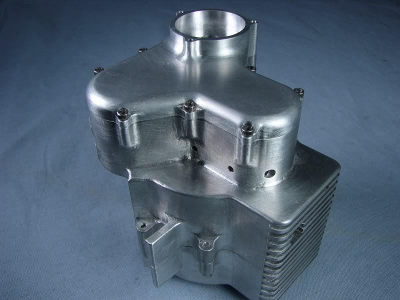
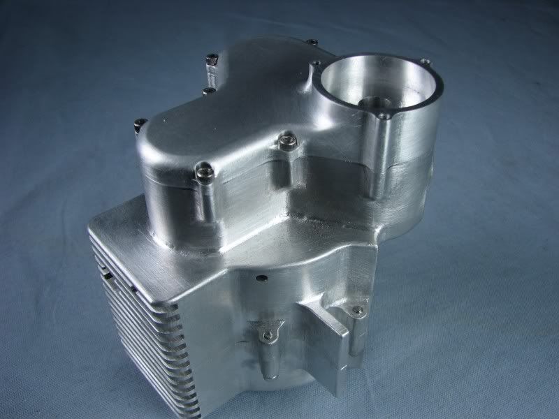
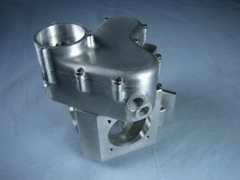
The block was removed from the vise and the burrs cleaned up and then flipped to start on the other side. After setting my height to clear my longest tool I repicked up my centers and moved to the distributor hole. I successively plunged end mills into the hole until I got to .95 diameter. (1.00 sharpened many times) I then went back with a .375 end mill and walked around the inside cavity to cut the bottom surface flat and to depth. Finally I put the new 1.00 end mill in and opened up the hole. The little bit of bottom relief on the end mill won't bother anything for .025 per side. The next step was to drill out the extra hole for the timing cover.
DE.jpg

DH.jpg
 
With the timing pocket finished I roughly layed out the radius around the bolt bosses on the timing boss and proceeded to rough away the extra stock to get down to the .25 thickness of the cover. The 2-56 socket head screws have a .14 diameter head and I needed to spotface the bosses down to .100 thick and also add a little clearance for the heads so I made up a .165 dia. drill rod cutter. Just a quick 2 flute. I center drilled a small hole in the center of a piece of .375 drill rod, filed the flutes to center, backed it off, hardened it and then stoned the cutting edges. I then spotfaced each of the holes down to leave .100 thickness for the mounting ears. The last thing for today was to step off the bottom radius. As per my normal habit I made a little sine/cosine chart, but on AutoCad, and walked around the radius. You'll notice in the last picture that I plunged out the tangent radii to each mounting ear. That way I have a witness to mill up to when I make my finish cuts. Tomorrow the rotary table will go back up to put the outside shape on the timing pocket.
gbritnell
DJ.jpg

DK.jpg

DL.jpg

DM.jpg


Very interesting, as usual, George.

Why did you drill the center hole in the cutter? Was it so the two edges don't meet?
I can see it trying to wobble in the cut if the edges don't meet precisely, but can't think of another reason.

Thanks,

Dean
 
Hi Dean, I just thought it would be easier to file the flutes into the small hole rather than trying to make them meet in the center. I already had a drilled hole so I didn't need it to center cut. Normally if I'm making some type of spotting cutter I take the flutes right to the center but I didn't want to set up my dividing head just for this quick tool.
gbritnell
 
Ripper Rita? ;D


Bob, you and I will need to consume a few pints and establish an Aussie to American translation guide......sounds like fun to me though..

George I'm gob smacked by your work as usual......I think....check that for me Bob.....thats a good thing right?


Dave
 
Thanks George, about that cutter. That's a good trick, actually, filing to the center of a hole.
I usually index to make my cutters, but sometimes spend two hours doing one up for a cut that takes 30 seconds. Your method will save me some time on the next flat bottom one-off cutter I make.
I can see this as being handy for a quick(er), odd sized piloted counter sink, too.

Dean
 
steamer said:
Ripper Rita? ;D


Bob, you and I will need to consume a few pints and establish an Aussie to American translation guide......sounds like fun to me though..

George I'm gob smacked by your work as usual......I think....check that for me Bob.....thats a good thing right?


Dave

Yes, gob smacked is good - gob is slang for mouth so it's a long winded very good verbal exclamation mark. Between this and Russian, I think we have done our share and let's allow George to continue his magnificent build.

Best Regards
Bob
 
Continuing the machining of the gear cover I next set up the rotary table and then went in with a .25 ball mill and roughed some of the stock from around the timing boss. Once the heavy stuff was out of the way I started spinning the boss down to the desired dimension being careful to just touch the witness plunges I had put in several steps back. I then switched to a .25 four flute and cleaned up the outside radius to the same reading I got when I was using the ball mill. Slow and steady is the key here.
With the timing boss out of the way I moved the cover over to the center of the other radius and spun it. Next I indicated the fixture square so that I could rotate the table to make the final cut on the angular surface, again going between the witnesses I had cut.
DN.jpg

DO.jpg

DP.jpg


The next step was to round over the edges. I had called out a .20 radius on my drawing but I already had a .188 cutter made up from the past and conveniently it didn't reach past the tops of the bolt bosses so the radiusing began. I did the angled face first as I was already there. With that done I did the corner radius because it was on center for the cleanup operation. The two lower side were next. I had planned on filing the stepped off radius on the bottom of the cover to my witness marks so I didn't want to move everything to that center to do the corner radius on it so I just bumped some witnesses with the radiusing cutter so that I would have something to file to. The first two pics show my homemade radiusing cutter, made out of a .50 two flute end mill and the start of the corner radiusing. The next two pics show the part with all the machining done and ready for the hand work.
DT.jpg

DQ.jpg

DR.jpg

DS.jpg


One other step before the hand work commenced was to open up the 2-56 tapped holes to .086 dia. for the mounting screw. The second picture shows an edge that was formed by the different cuts that were made. The next picture shows the corner roughed off with a small burr. One thing that I have learned when using small burrs is to let them do the cutting. By that I mean just a light touch is all that's needed otherwise the burr will grab and walk across your job leaving you drained of all spirit, especially after all this work. The next picture is some file work applied to the same area, a small triangular file and a homemade round riffler file doing the job.
DU.jpg

DV.jpg

DW.jpg

DX.jpg
 
The next two pictures show various stages of filing, in the fillets, around the bolt bosses and on the large corner radius.
DY.jpg

DZ.jpg
 
After filing everything, flats, bosses, radii etc. I used varying grades of emery to clean everything up. Once that was done I went over everything with a fine Scotchbrite pad and then up to the utility tub for a scrub with scouring cleanser and an old toothbrush. It gives it a nice satin finish. Here's the result, one timing cover with nary a screwup, some close calls but nothing that couldn't be hidden with some judicious filing and sanding.
EA.jpg

EB.jpg

EC.jpg

ED.jpg
 
Wow, such a beautiful engine. Ever done any mold and die work?
 
It's actually starting to look like an engine now, or at least a neat mechanical lump. I generally always use hex bolts for my engines but this one being of the motorcycle type just cried out for stainless socket head screw. I think it adds to the character.
Tomorrow the timing cover and the crank cover and I can start on some of the internals. I'm not going to post every part but just the ones that take several setups to do, the crank, the cams and most certainly the cylinder heads.
gbritnell
EE.jpg

EF.jpg

EG.jpg

 
Hi Vernon, I consider myself one of the luckiest people in the machining field. I learned metal patternmaking from some of the greatest old timers in the business. That was many years ago and most of them are gone now but their skill lives on in what I do. I worked on patterns and coreboxes for the Ford Motor Co. foundry in Cleveland, Ohio. When I got into the trade most of the work was still hand fitting and filing. It was a craft from a bygone era now replaced with CNC.
gbritnell
 
DAMN!!!.... just Damn!!. <crickets chirping>

Steve
 
Holy Cr@p! This thing just keeps getting more amazing. I couldn't make something like that even if I were willing to spend the thousand hours it would take me! :bow: :bow: :bow:

Chuck
 
That's just beautiful, George. You're hearing that a lot now, but what else can be said? If someone told me that was not a casting, I'd be inclined to think they were full of meadow muffins. Looks like something that came out of the Norton Villers custom shop during the UK's great motorcycle heyday!

Would you do us a favor next time you get into the shop, please? Take a photo of the rifflers you use for this work so we can see what you're working with. (I'm kind of interested in files and filing..)

Thanks for this great sharing/teaching/learning thread.

Dean
 
Im still searching for the superlative....latest in the running is Cedge's

Cedge said:
DAMN!!!.... just Damn!!. <crickets chirping>

Steve


That doesn't begin to describe it......but its getting closer

Nice George!....

Dave
 
Gee whiz...one day I'm looking at some hunk of metal with some bits being chewed off...I turn my head and look back...and today I see an amazing piece of work. Wow.
 

Latest posts

Back
Top