90 degree V-twin engine

Home Model Engine Machinist Forum

Help Support Home Model Engine Machinist Forum:

This site may earn a commission from merchant affiliate links, including eBay, Amazon, and others.
Thanks for the explanation, George. I knew there would be a good reason for it!

Dean
 
I made a little more progress on the right crankcase. I drilled all of the holes, machined the oil pump pocket and started roughing the inside of the gearcase. I tried to design it so that most of the bores or counterbores are standard sizes so that standard tooling, end mills, drills and reamers could be used. The second photo shows all the internal operations completed. I then started roughing some of the stock from the outside. I made a chart up so I could plunge out the fillets on either side of the bolt bosses. After that operation I went back and cleaned out the stock between the fillets. In the second to last picture you can see how I step around the bolt bosses. I make up threaded plugs that match the radius of the boss, screw them in and then bump up against them with the end mill. This gets me close so that I don't have so much hand work to do. The next two pictures show the step off milling around the lower radius of the gearcase. I was debating doing it this way or using the rotary table but I have many more operations with the vise set up so I just stepped it off. The last picture just shows the pile of aluminum chips. What's not shown is there's just as many on the floor. Time to shut down and get the shop vacuum out. The chips are starting to follow me all over the house.

VTWINQ.jpg

VTWINR.jpg

VTWINS.jpg

VTWINT.jpg

VTWINU.jpg

VTWINV.jpg

VTWINW.jpg

 
George,

Beside the great machining you do. The only thing we have in common is the chips!

Thanks for the Lessons

Tony
 
I wouldn't say just the chips. I've seen some of your work and it looks pretty good to me. I really enjoy scratch building. It makes it more interesting seeing the part emerge from the block of aluminum. With this side of the crankcase it's going to take a lot of whittling to get it to it's finished state. I'm used to reindicating my part every time I move the head up and down but at times it get a little frustrating when I get ahead of myself and don't leave enough room for one tool. Building this thing from my own drawings helps me find omissions on the print.
gbritnell
 
I know nothing about this type of engine, so excuse the question: are you going to turn the block over and machine a matching section on that side?

In any case, everytime I see your builds I learn something new. :bow:
 
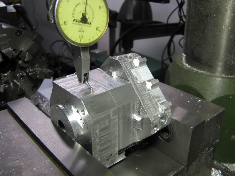
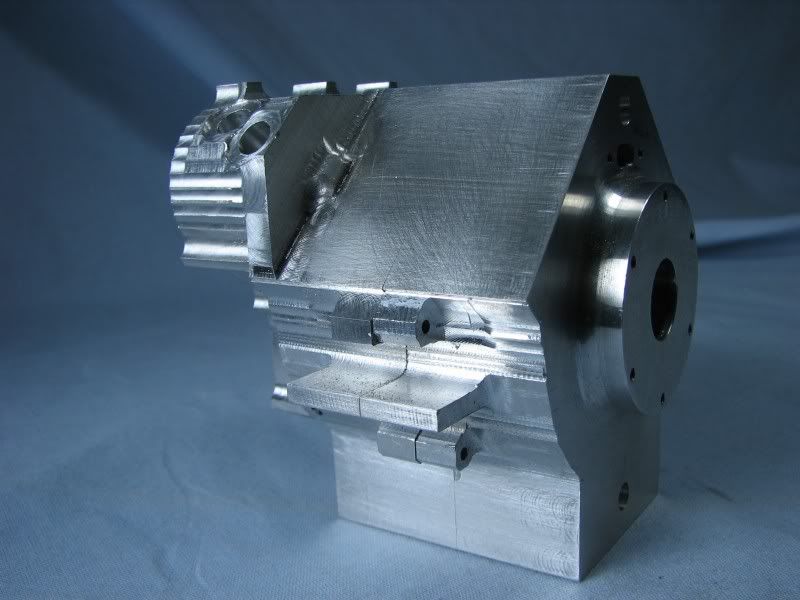
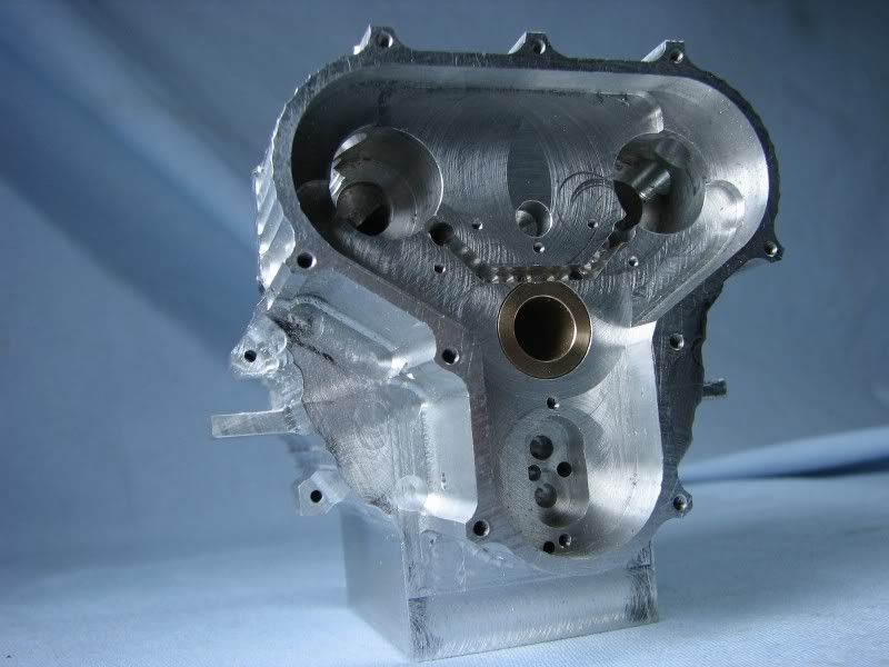
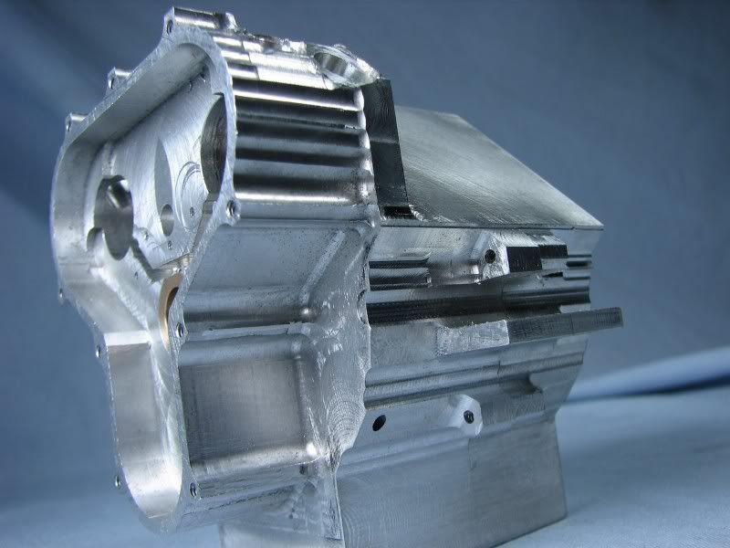
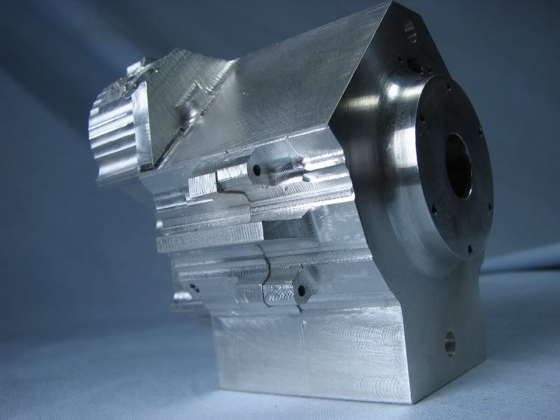
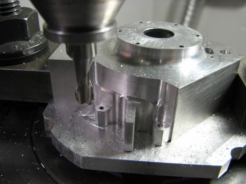
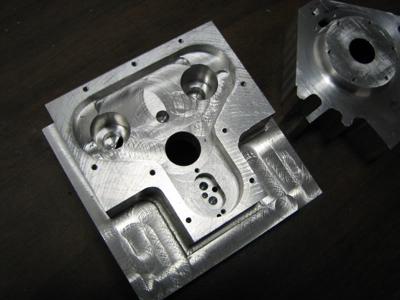
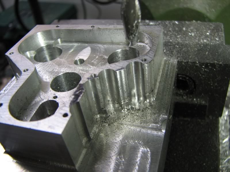
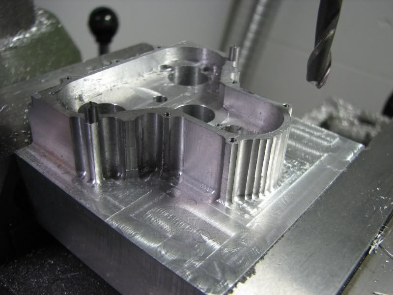
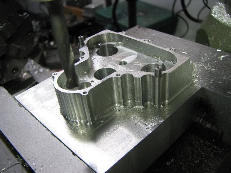
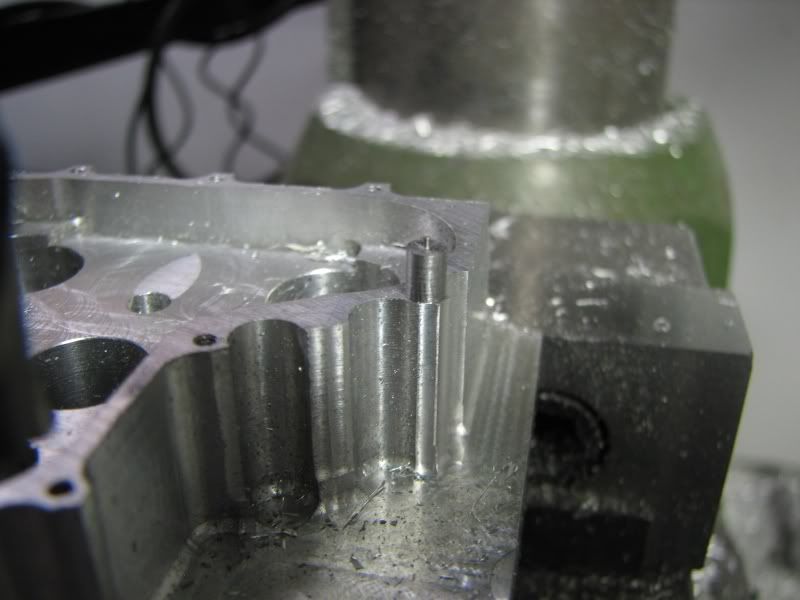
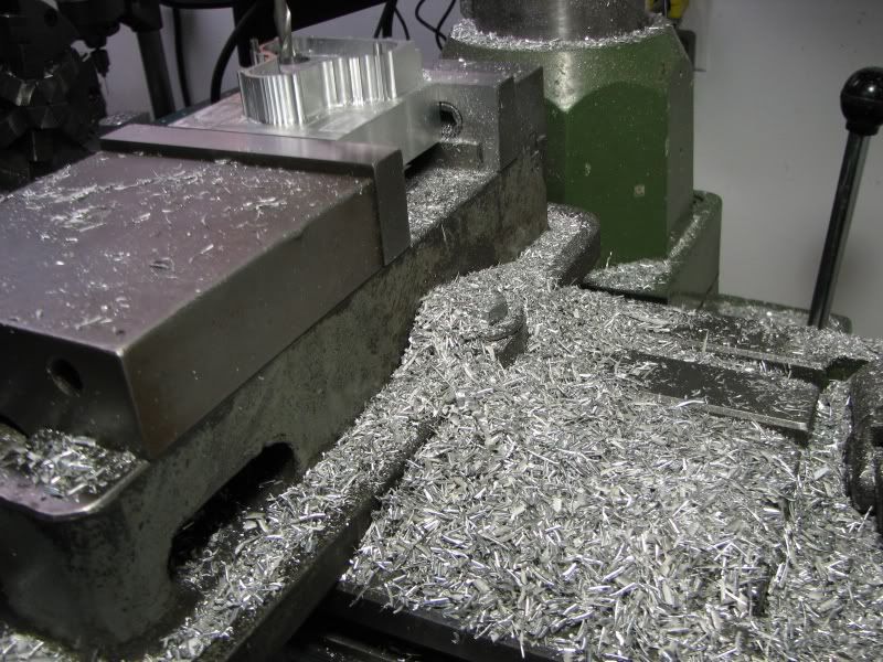
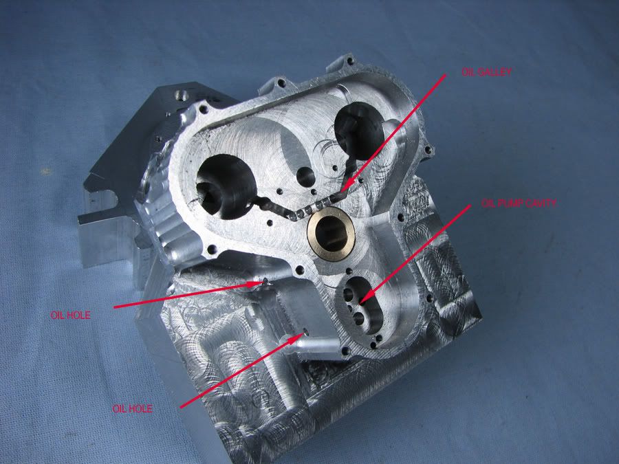
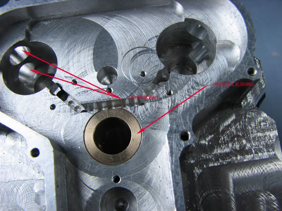
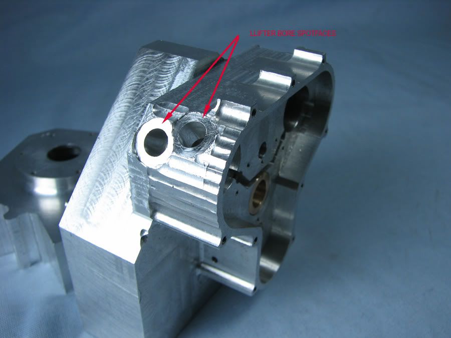
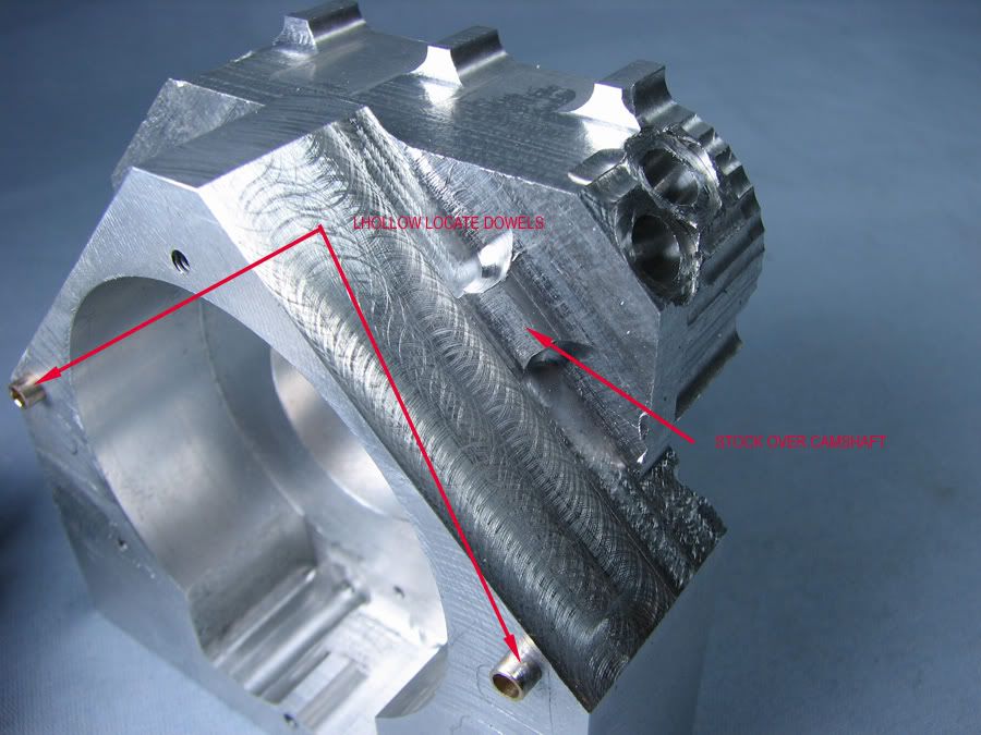
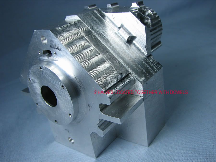
Kvom, yes, when I get finished machining this gear case I will start on the other half of the shape. Although I have a fixture to mount it on I wanted to get as much cut in the vise first. A rigid setup is always the best way to cut. I have to cut the two lower angled walls, drill the oil passages and bore the lifter holes and then I can cut the other half. I will also need to drill my fixture to hold the gear case side so that I can finish up the rotary milling on the other side. When both halves are machined they will be set up to do some ribbing on the bottom of the oil sump, much like the oil pan on the Whittle Aero v8. Other than the camshafts the remaining machining is quite straightforward. The gears are all 32 D.P. I have gear cutters for making the larger ones but will have to order the 2 small 8 tooth gears for the oil pump. I looked in the tool catalog for a cutter to cut these gears but they only list down to 12 teeth. I receive the iron for the cylinders the other day and also the main bearings which will be sealed ball bearings. The oil pump will lubricate the cams and the big end of the rods by way of the crank.
gbritnell
 
Great looking engine George!....That is going to be a bit of "wittling" isn't it.

Dave
 
I've always been interested in this kind of engine. Looking forward to seeing and learning more.

This kind of project and quality is WAY down the road for me.
 
I got some more chopping done. Little bits at a time because it's to the point that I don't want to start over. I go by my dimensions but leave everything about .01 heavy until I can see where I'm at. The oil galley hole goes from the pressure side of the pump up to the crank and then up to the cams. I drilled cross holes, .081, to meet the main hole. I then milled down .187 with a .062 end mill to connect the drilled holes to the cams. This slot will have a cover plate over it as you can see the tapped holes above and below the slot for securing the plate. Right before the oil passage goes into the cam cavity it will have a restrictor bushing with a .03 hole in it. This will keep pressure in the system. I then mounted the part on the fixture plate and in my dividing head so that I could rotate it to do multiple surfaces. I finished trimming around the gear cavity and then started on the lifter bores and spotfaces. I rotated the part to 45 degrees from vertical and made a witness cut to within .005 of where I needed to be. I then rotated the part 8.3 degrees to either side of 45 to put in the lifter holes. Each hole required resetting center as the part is rotating around the crank hole. The clearance for the camshaft is .562 diameter so I inserted a piece of brass rod into the hole and touched off my edge finder then moved to center. The bores were put in and then I had to step off the counter bores as they overlapped each other on an angle. You can see the angular contact line between the two bores. I then picked up my radial steps with a ball mill and carried them around the counterbore witnesses. The last thing I did for the day was to remove the excess stock from the cylinder base area. Here again I left about .007 stock so that when both halves are bolted together I can clean them up together. The two halves are located by a .140 hollow dowels. The 3-48 screws go through the center of them. Now on to the pictures.
gbritnell
VTWIN1.jpg

VTWIN2.jpg

VTWIN3.jpg

VTWIN5.jpg

VTWIN4.jpg


Geez George, that looks fabulous!

Nice Work and I am amazed as usual! :bow: :bow:

I have been admiring the Westbury Wallaby for some time....think I'll finish modeling that up.....for a "hogment".....ah yet another project... ::)

Dave
 
Very interesting and nicely executed machine work, George.
Any compliments I can think of seem kind of underwhelming considering the scope of your project!
I'll just say "wow".

Dean
 
George...
I'm in awe, not only of the machining process, but all the pre-planning that is becoming so obvious as you work.

Steve
 
I put the two crankcase halves together and scribed the outline from the one to the gear side case. I then sawed the big chunks off and then set it up in the vise and started milling close to the lines. After roughing everything off I put the case halves back together and set them up in the mill to match all the surfaces. The first case had all the major surfaces to size so it was just a matter of indicating them and trimming the gear side case to match. Now that all the roughing and vise milling is complete I can tear everything off the mill and set up the rotary table to do all of the radii. That should do it for the milling and then I'll have about 6 hours of hand work, radiusing corners and filing and sanding.
gbritnell
VTWINBK.jpg

VTWINBM.jpg

VTWINBN.jpg

VTWINBO.jpg

VTWINBP.jpg


Holy macaronis!

That is really starting to take shape George! Bravo!
 
I took the vise and dividing head off the mill and set up the rotary table. The first shot is indicating the center of the table. In the next two pics I made up a plug to go in my holder and locate the center of the crank hole. With the table on center and the part located it was clamped down.
BQ.jpg

BR.jpg

BS.jpg
 
These pictures show the progression of cuts at the desired radius. The first cut was to the top of the motor mount pad, the second was to the top of the bolt bosses and finally down to the fixture plate. The last cut was the trickiest cut because there wasn't much room between the bolt boss and the motor mount pad. First one side was cut, then the other.
BT.jpg

BU.jpg

BW.jpg
 

Latest posts

Back
Top