V-TWIN---MAYBE V-4

Home Model Engine Machinist Forum

Help Support Home Model Engine Machinist Forum:

This site may earn a commission from merchant affiliate links, including eBay, Amazon, and others.
Okay--I've used up all of my good will for the day. I actually did have that cylinder firing on it's own, running the engine this morning. I have been making minor adjustments ever since, and if anything, I've made it worse. Tomorrow is a new day, and hopefully I will have better success tomorrow.---Brian
 
When all else fails---we get a bit more scientific. This picture shows me adjusting the intake cam so that the intake valve actually begins to open 15 degrees before top dead center.
0RjNqt.jpg
 
This is re-do of the last picture posted. Note that the end of the dial indicator is resting on the end of the rocker arm, which is resting on the end of the valve. Doing it this way eliminates the movement that the rocker arm makes before it contacts the end of the valve stem, due to the valve lash. (gap between push-rod and adjuster at end of the rocker arm.) Next task will be to reset the ignition cam, and then I should be able to start the engine and run it on this single cylinder.
b5uH13.jpg
 
I haven't ran off with the gypsies. I've been very busy with other things and doing "design work for pay" so I can afford my hobby. I reassembled the right side cylinder and it is running. I did make one change to the aluminum camshaft support so that it gave me better access to the cams, to tighten the set screws in each cam so as to set the correct cam timing. I've learned something there---If a engine component has to be repositioned and the set screws tightened in two or three different places to get it right, then a #5 set screw is too small. Actually, not the set screw itself, but the tiny 1/16" hex wrench hole. It takes very little to round the corners on the set screw hex and very little to round off the corners on the wrench.--Live and learn!!! You will see in the picture that I have made a second flywheel from steel and bolted it in place, in addition to the brass flywheel. This may be a temporary thing, until I get the engine running the way I want it to, or I may have to leave it in place. Nothing more to report at this time, but sooner or later I will get the engine running on both cylinders and post a video.---Brian
z18JQy.jpg
 
Last edited:
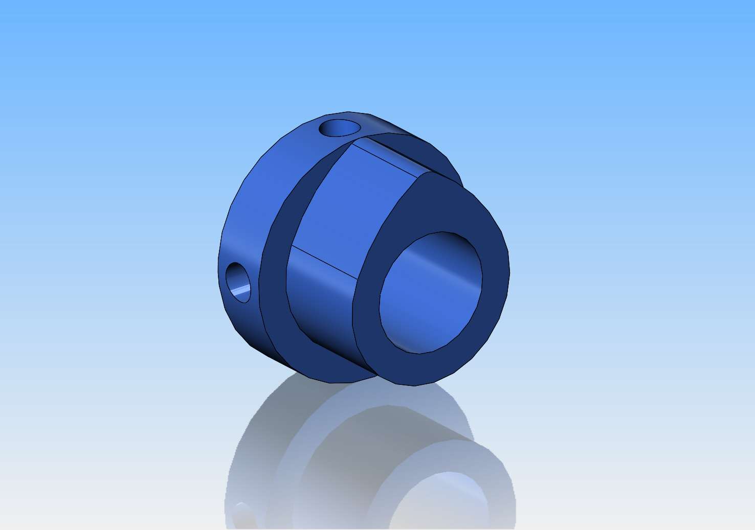
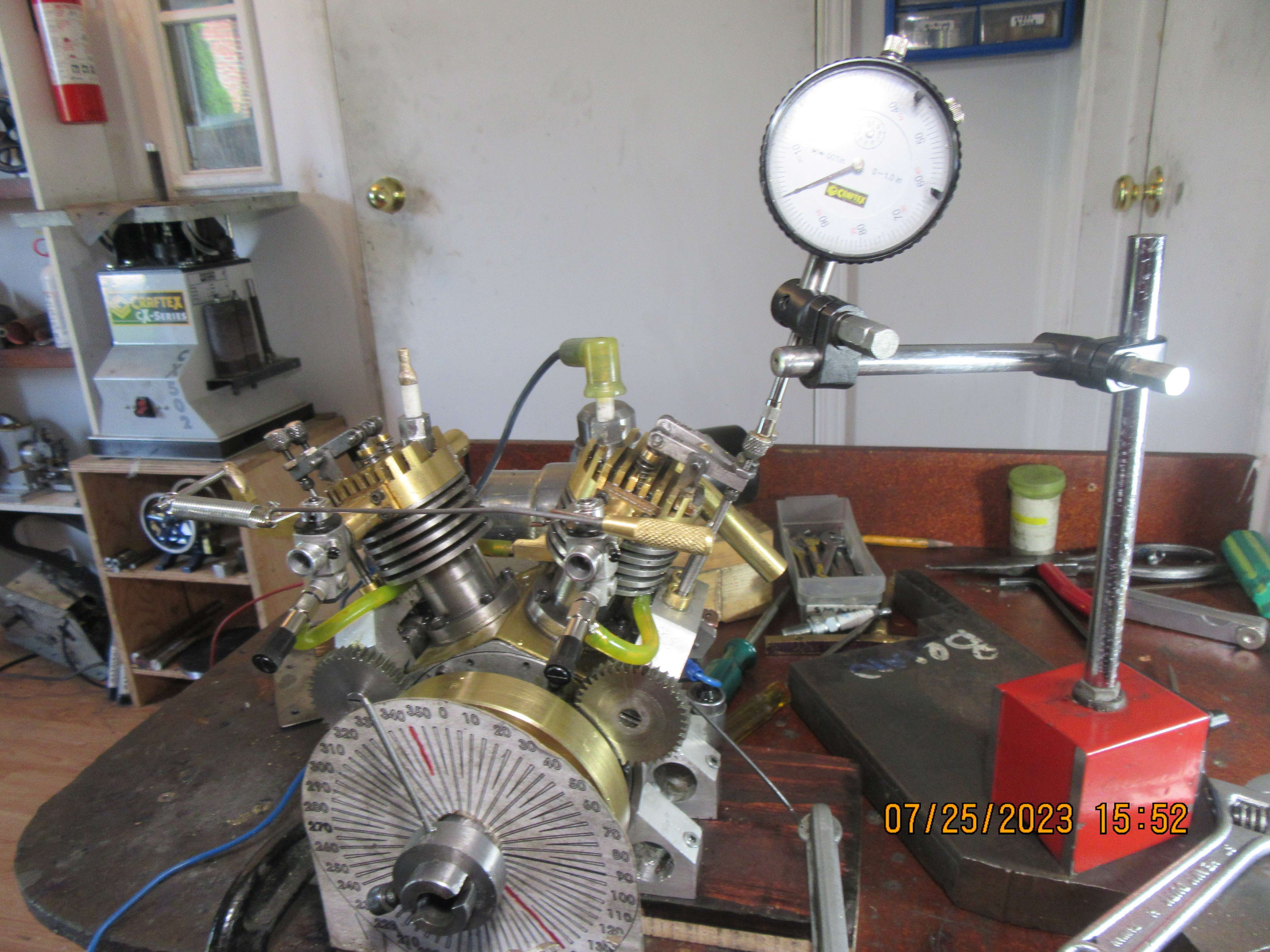
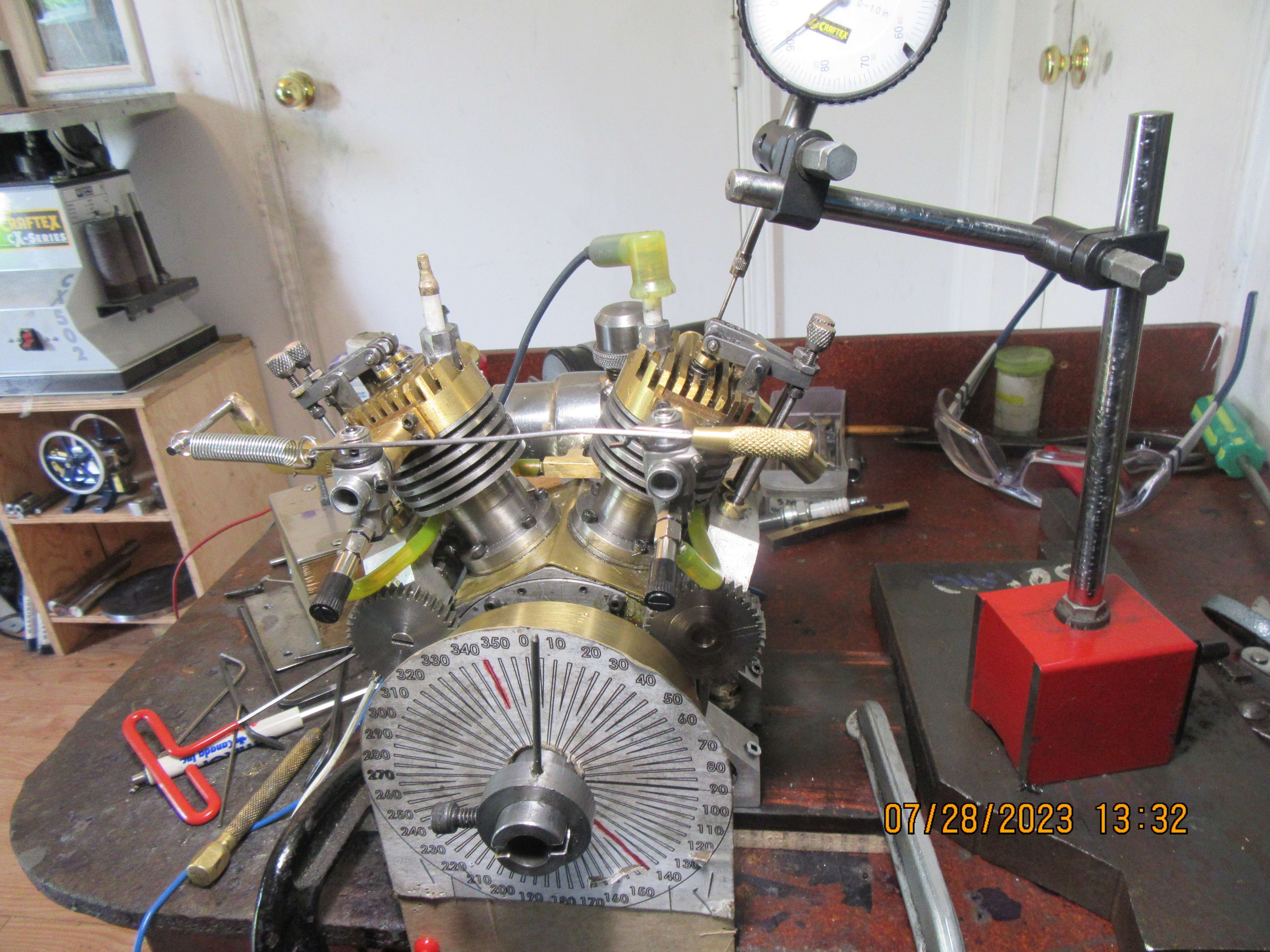
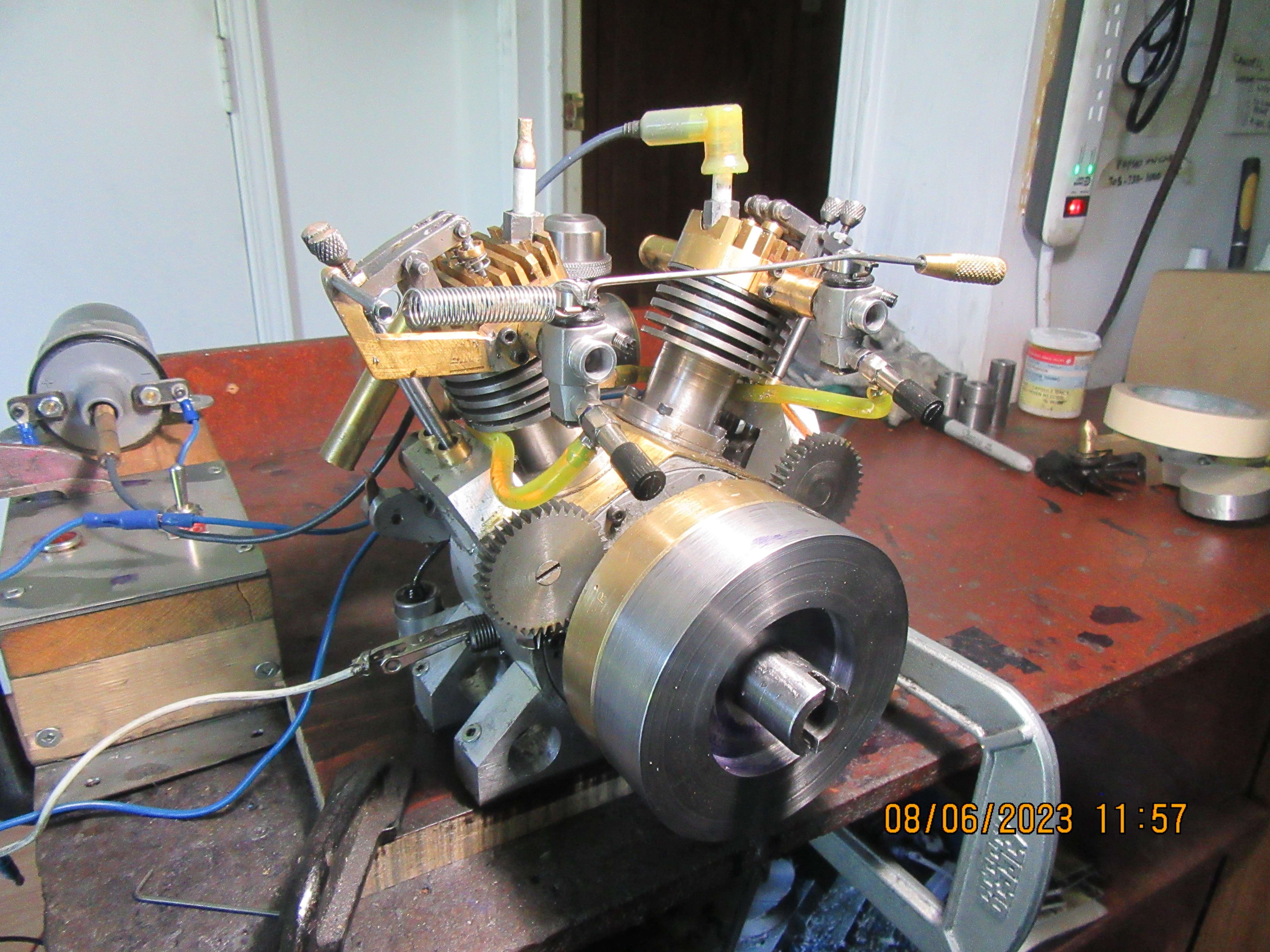
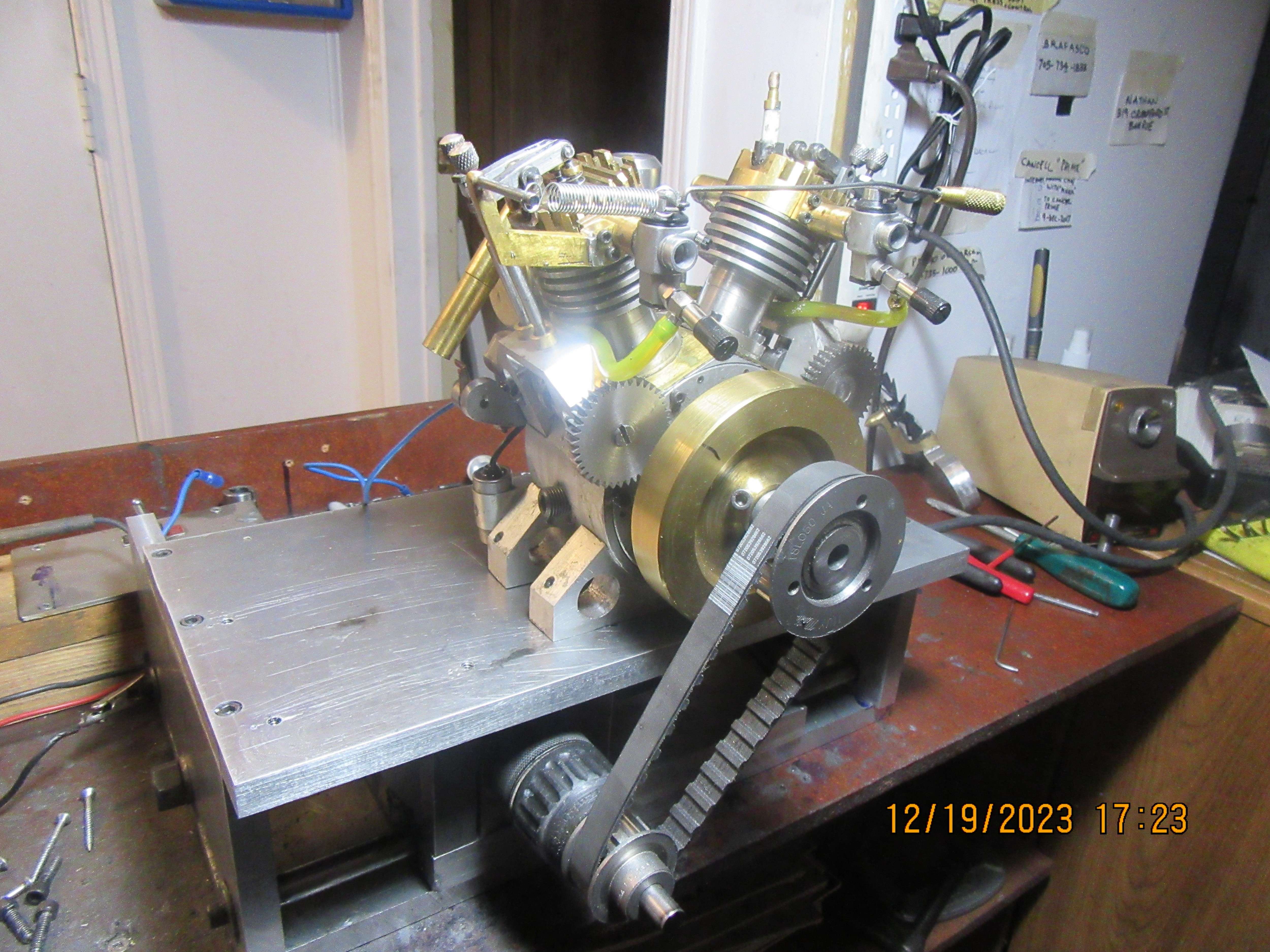
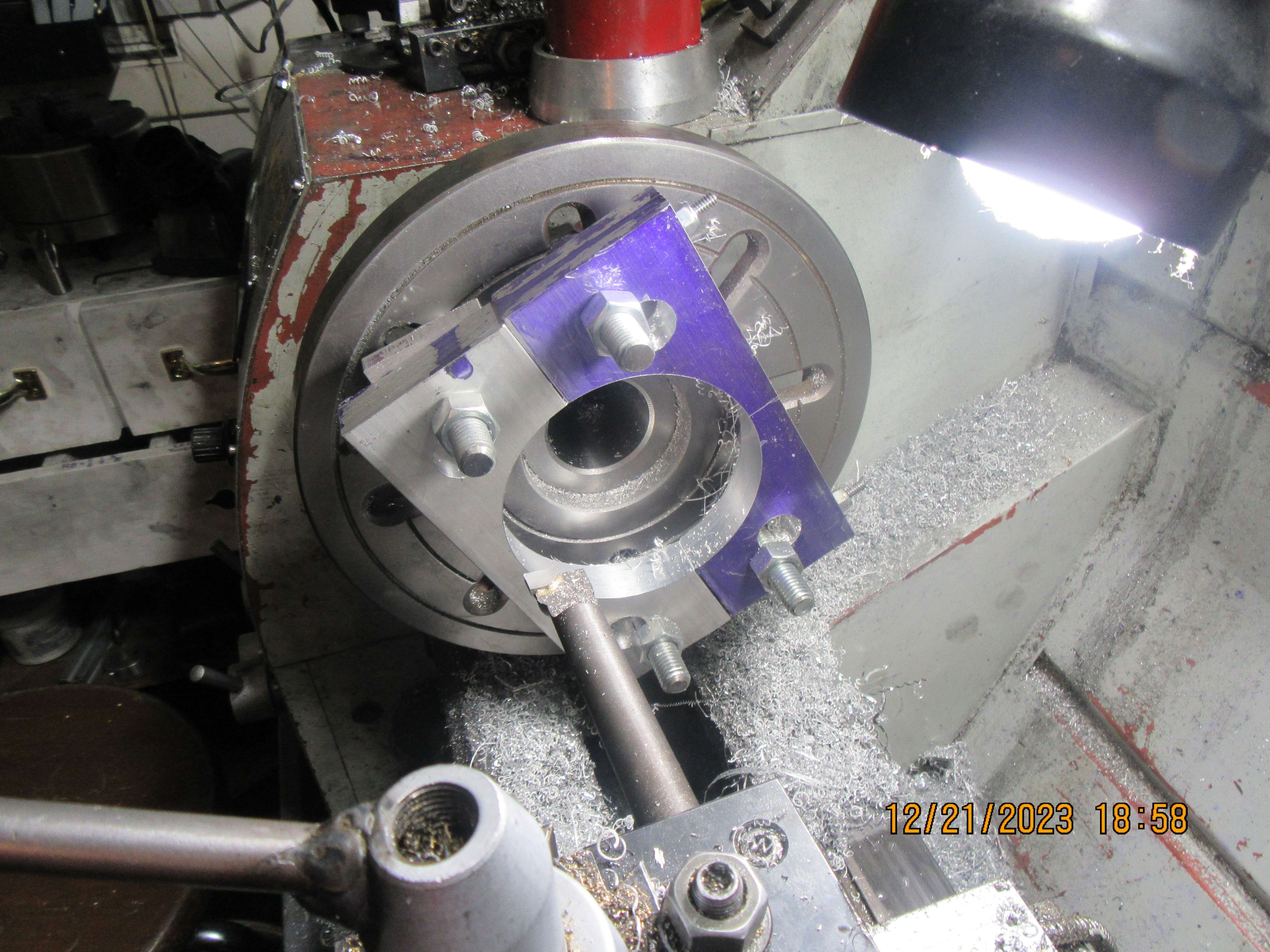
Today I have a little story to tell. It's a rather interesting story. When I first built this engine, I had a couple of very fast, very good runs with it. I knew at that time that with some finessing, the engine would be a good runner, and it would be safe to sell plan sets for it. I like my engines to run slowly---in fact, the slower the better, as far as I'm concerned. I could never persuade this engine to run slowly, and for the last few weeks I've been struggling to find out why. When I make my cams and lifters, I make them from 01 tool steel, heat to red hot with oxy acetylene torch, and drop them into a can of motor oil. This thru-hardens them, and since they never see a lot of "shock" loading, I don't bother to re-heat them and draw them back to a softer state. The model of the cam which I have attached has a 5/16" bore (To give you an idea of overall size) and four drilled and tapped #5-40 holes around the shaft to lock the cam in place on the shaft. The ONLY reason to have four holes is that when I time my engines there is limited access to the set screws, and having a tapped hole every 90 degrees guarantees that I will be able to reach at least one of them to tighten the cam in place on the camshaft. Today I disassembled one of the camshaft supports, and removed the camshaft, to get a better look at what was actually happening. The threads were put into the cams before they were hardened. For some reason, and I don't really know why, the threaded holes were "closing up" near the bore. I found that when I had the camshaft removed, a set screw would thread into the holes in the cam like they were supposed to, but when fully tightened, they weren't locking the cams onto the camshaft like I thought they were.--the screws were binding up in the tapped holes and putting very little locking pressure on the shaft!!! Of course, this would initially let the engine start and run, and then the cams would slip on the cam shaft and throw the engine out of time. I have some very good #5 taps, and when I ran the tap thru the previously threaded holes, the tap would try and lock up in the hole before it broke thru into the bore of the cam. As I said, they are very good taps, and with a bit of light cutting oil and some serious butt clenching, I was able to run the taps all the way thru into the bore of the cams. Now the set screws will go in full depth and bear against the camshaft to lock the cams in place. This is probably my fault. I should have ran the taps thru the tapped holes immediately after hardening the cams.---Brian
1UB28E.jpg
 
Brian, I do enjoy the problems you find because the solution is something no-one else could determine (see the dozens of posts that all missed the truth!). For that you are a genius! Not just finding new problems, but finding the reason why and determining a solution. That takes a bit of brains and study! Well done.
As to "why?" the threads have shrunk, I can only guess it is something metallurgical in the crystalline structure that has changed because of heat treatment. My only experience is measuring exhaust manifolds on car engines, made from Cast Iron and from Nodular cast iron, or steel.
The cast iron manifolds shrunk after prolonged use at high temperature, so much so the holes began to bind on the mounting studs and break... So the nodular iron manifolds were tested and were OK. But a later development of the same engine used steel fabricated manifolds (to mount Turbos and catalysts) and when checked had much less shrinkage between studs at the interface with the exhaust gasket on the cylinder head. (If I remember correctly... from 30 years ago!).
So perhaps your cams were shrinking similarly? - I guess 01 Tool Steel is a "high carbon" steel, (not "high" like cast iron, but more than mild steel)?
Not being a metallurgist, I would love to hear an expert's explanation of this.
K2
 
Martensite (the micro-structure of hardened steel) is slightly less dense than ferrite. So there should be some volume change associated with hardening, it probably affected the thread clearances.
 
I too struggle with cam lobe positioning and timing. Lately I've been fixing the cams initially with super glue. It holds enough to run the engine and is easily loosened with a little heat and or the dissolver. Once I'm happy with the cam settings I pin them to the shaft with 1/16 split pins.
 
Tapping a piece of hardened steel with a high speed tap will ruin the tap. Hardened O1 can be as hard as 65 C which is the same as most HSS taps
 
Last edited:
George--the cams had been tapped before hardening. All I was doing by running the tap thru them after hardening was cleaning the crap out of the threads that accumulated during the hardening process.---Brian
 
What tapping compound do you use Brian? ("Light cutting oil"?) - I bought some at a Model Engineering show - unknown brand - and I am sure it is tooth polish - as used by dentists when shining your pearlies! - even smells of mint! But it gives tasty results tapping everything. Maybe ordinary toothpaste wound do?
I was told (years ago) that toothpaste was the same as used by diamond cutters to polish diamonds (Wrong!) - and it would remove scratches from a scratched motorcycle visor.... well it removed them by making the whole visor uniformly opaque with scratches! - Bad move!
For cleaning-up a thread, I'm sure the tap would have been strong enough, but maybe it just took a thou or so off the thread (Oxide?) in the process, so with your experienced and skilled "Butt-clenching" it worked for you. We need to learn more tricks like this one!
😉
K2
 
Brian, I have found that parts in the 5/16-7/16 diameter range will grow about .001 when hardened. If you measure your finished cams and find this to be the case then the tapped hole has also changed size. That being said I would have a dedicated 'chasing' tap to use strictly for clearing the holes.
 
George--I knew that cast iron will grow a bit when heated and then cooled. I haven't really seen that happen in 01 steel parts, but I haven't really looked for it either. I can remember men in our machine shop chasing threads on parts that had been sent outside for hardening. It's a step I overlooked on these cams, but in future I will chase the threads on anything else I harden.----Brian
 
Martensite (the micro-structure of hardened steel) is slightly less dense than ferrite. So there should be some volume change associated with hardening, it probably affected the thread clearances.
FWIW, taps come in different sizes, there is an 'GH' tolerance designation on ground thread taps that designates the oversize in 0.0005 increments. A normal/standard tap is a GH3 which is 0.0010 to 0.0015 oversize. Also, there are steels that will shrink or grow, some shrink/grow more than others and they shrink/grow relative to the grain/rolling direction of the steel, from experience, I've used 3/8-16 UNC, GH5 taps, that would be 0.0020 - 0.0025 oversize, in D2 at Rc60-62 to get acceptable threads.
 
Last edited:
A lesson I have learned here.... "Chase threads, not girls, ....!" - At least where Engineering Models are concerned! There are more puns than I can safely use here (e.g. "... for easy screwing") - without being censored!
The Engineering dictionary is full of Double entendres...
K2
 
The time has come, the walrus said---To take another look at this engine. It has never ran successfully. I've had it running on the right hand cylinder, I've had it running on the left hand cylinder, and I've briefly had it running on both cylinders, long enough to take a video of it. I was very pleased to see, today, that my gearbelt pulley with the one way clutch will fit on this engine. I'm going to make a couple of different "feet" for the engine so it can be bolted to my starter table, and then do my very best to get the darned thing running on both cylinders properly.
tpEwZw.jpg
 
Today seen a good start on making new "support feet" for the engine on my lathe faceplate. I have to do this in order to bolt the engine down to my new "starter table". If I was smart instead of good looking I would have cut most of the material away on my bandsaw and just cleaned up the hole on my lathe. Of course I never thought of that until I had everything set up ready to bore---headslap!!! My largest diameter drill is 1" o.d. and the hole ends up at 4.00" diameter. You might say that I had a very "boring" time tonight after supper.
psevBS.jpg
 
Perhaps Boring fr the metal, but maybe that is a part of the hobby, having a half-shift siply machining... - Like Fishing, sometimes the best bits are the quiet ones, where life moves a bit slower and stresses are relieved, as slowly the finished article appears from imagination to reality?
K2
 

Latest posts

Back
Top