90 degree V-twin engine

Home Model Engine Machinist Forum

Help Support Home Model Engine Machinist Forum:

This site may earn a commission from merchant affiliate links, including eBay, Amazon, and others.
I cant think of the right words.... like Zee said ...WOW...... gorgeous.. you must be so proud..... :bow:
 
George,

Your a true :bow: Craftsman :bow: and a great story teller of how you learned the craft...

Thanks for sharing

Philly
 
Amazing, really don't know what to say any more - just keep watching in awe! :bow:
 
OH MY!!!!! th_confused0052 th_confused0052 th_confused0052


Ron
 
Most definitely a tough act to follow here and the bar has been lifted far beyond any of my abilities. But to work on some of these shortcomings, I would like to see how you make some of your tools.
 
Smashing bit of work.

Thanks for sharing

Stew
 
I finished the two outer covers, the one over the ignition housing and the one over the crankshaft end. No WIP's on these, just some turning, drilling and hand work. I purchased some stainless oval head screws for the crank cover. I really like the way they look.
gbritnell
EJ.jpg

EH.jpg
 
Thanks for the additional pictures, George. Besides your fine work, you've got a pretty good handle on lighting shiny objects.

I have the feeling that I'm watching the construction of a museum quality piece, here.
Functional art in the making.

Dean

 
Yes, Your pictures are top quality! Thanks for sharing this with us.
 
George,
Are you doing 2 stick cams or planetary cam (like a Radial)? I can't seem to tell yet, looks like 2 sticks are going to happen. If you are going to hobb your own gears (which I already know you will) Lesson please....please. With index RT.

Tony
 
Hi Tony, it is going to have two cams. The crank gear drives an intermediate gear which then drives both cams. The cams can then be on the cylinder centerline instead of offset. I am cutting the gears for the cams. All of the gears are 32 pitch and I needed to order the gears for the oil pump so with only having two 32 pitch gear cutters I ordered everything but the cam gears. I will make a WIP when I get to that point.
George
 
Not a great amount done today. I made the oil galley cover and the 0-80 screws and also the oil pump cover with 1-72 screws. I realized that the oil drain back hole in the bottom of the gearcase is a little to close to the hold down screw so I'll have to change the drawing. I guess the good thing about building from one's own drawings is the features that need modifying can be done right away.
gbritnell
EK.jpg
 
gbritnell said:
Hi Tony, it is going to have two cams. The crank gear drives an intermediate gear which then drives both cams. The cams can then be on the cylinder centerline instead of offset. I am cutting the gears for the cams. All of the gears are 32 pitch and I needed to order the gears for the oil pump so with only having two 32 pitch gear cutters I ordered everything but the cam gears. I will make a WIP when I get to that point.
George

Thanks George, I think I've got a handle on how to do gears but it would be nice to see it happen.

Tony
 
This one's for you Tony and any others that haven't done it. The subject is gear cutting. I had a 32 DP cutter for my cam gears but didn't have the right ones for the others so I ordered them. It was less expensive than buying two more cutters at $25.00 each plus shipping.
This particular gear is 28 teeth. The pitch diameter is .875. The outside diameter is 1 divided by the pitch giving .0312 (addendum) .9375 diameter. Dedendum is 1.156 divided by the pitch, .036. The whole depth is addendum plus dedendum, .067.
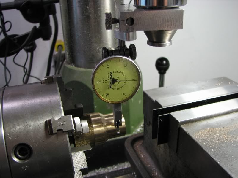
The stock was turned, drilled and reamed then mounted in the dividing head.
Everything was indicated to make sure it was running true and parallel to the table.
AINDICATE.jpg


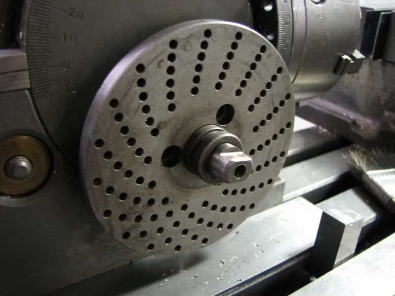
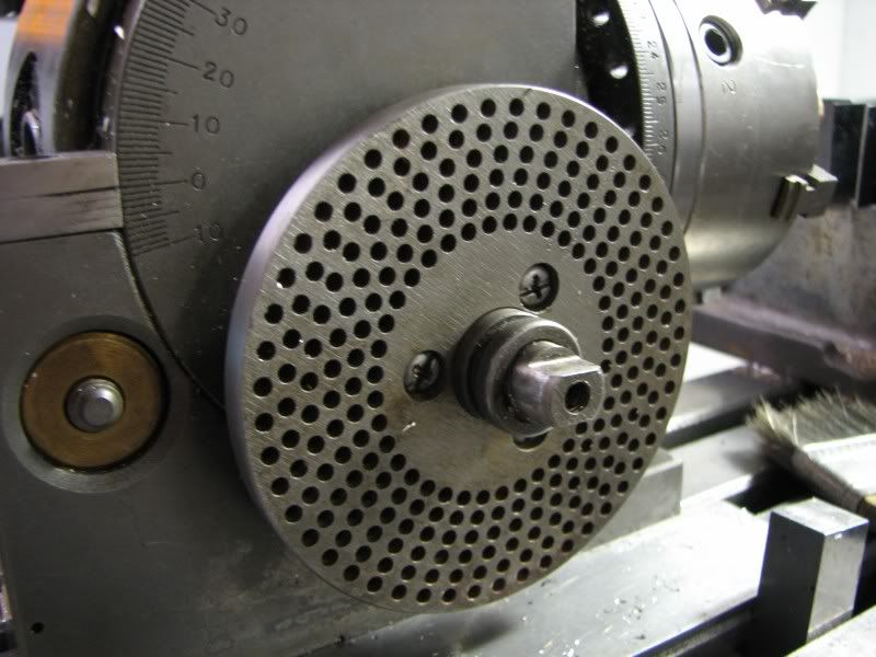
Next was to change index plates. I had to switch to a 49 hole plate to cut this gear. After the new plate was installed the quadrant and handle were reinstalled and the pin in the handle was engaged in the 49 hole row before tightening the handle clamp screw.
BREMOVEPLATE.jpg

CINSTALLPLATE.jpg

DSETSELECTOR.jpg


The quadrant arms have to be set for the proper spacing which in this case was 21 holes on the 49 row. You count 21 holes from you handle pin, not the hole that the pin is already in.

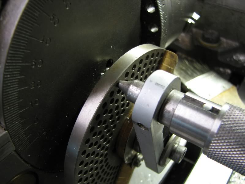
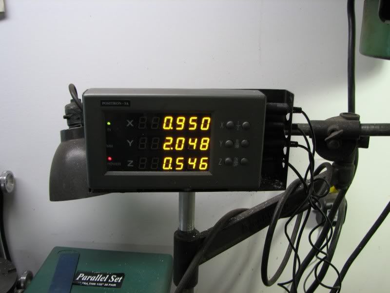
Next was to set the cutter height. I use a piece of .002 stainless shim to touch off my tool. With that set I calculate my drop to center which is half the cutter width plus half the stock diameter. You can see it on the x reading of digital readout.
ESETCUTTERHGT.jpg

FTOCENTER.jpg


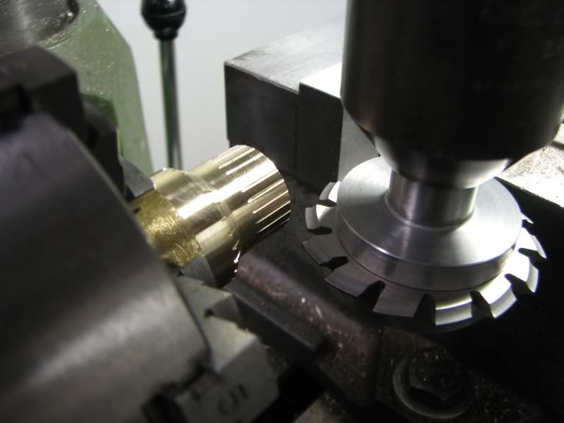
Now I touch and go in .004 and make a trial cut around the part to make sure I've got the right amount of teeth. My numbers are right but the old adage holds true, measure twice, cut once.
GTRIALCUT.jpg


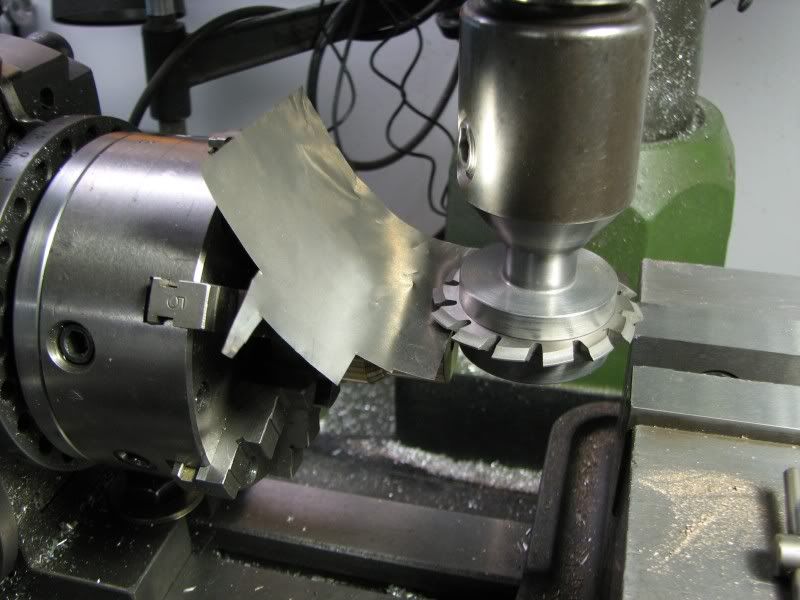
Everything looks good so being as I'm cutting brass I only need to make one pass so I go to the full depth, y reading, and start my passes. My procedure is this: make my cut, disengage the handle pin and rotated 1 revolution plus the 21 holes on my quadrant spacing, rotate quadrant until it's up against the pin and then make the next cut. On a gear with large teeth like this it's not hard to tell where you're at but with fine pitch teeth and a great number of them you have to remember to be consistent with moving the quadrant every time.
GTRIALCUT.jpg


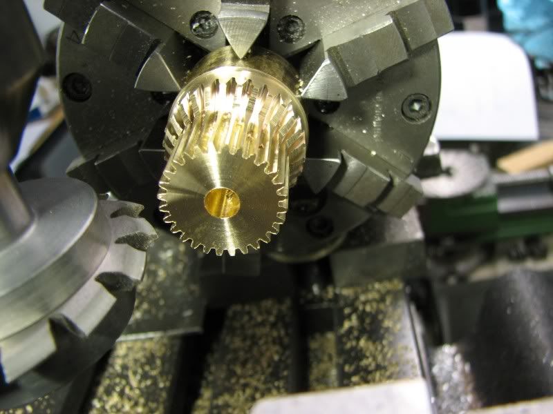
A number of cranks and cuts later this is what you end up with.
JFINISHGEAR.jpg


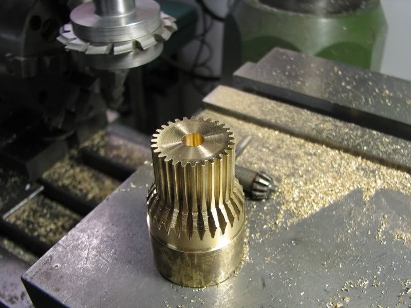
The last picture is the blank with the edge filed and the teeth deburred ready to be parted off to the appropriate thickness.
KRDYTOCUT.jpg


It's not that complicated of a job. The most important thing is to keep track of where you're at. If you get an interruption finish your pass, stop and don't move anything until you get back.
I know there are all kinds of tutorials and videos out there on the subject but it never hurts to see it again, especially if you don't do it often.
gbritnell


Fantastic George. Always good learning to watch your posts.
How did you deburr the teeth?
 
zeeprogrammer said:
Fantastic George. Always good learning to watch your posts.
How did you deburr the teeth?

With a good tooth brush?
 
Hello George,

Beautiful work and a fantastic job of documenting your progress. I am thoroughly enjoying every post. Thank you for taking the time to do so, you are inspiring many with your efforts.

With regards to your gear cutting set-up, did you climb cut this gear because it was brass? Would you have done the same if it were made of steel or cast iron and the same relative size?

Kind regards,
Mike
 
Hi Mike, thanks for the comments. As to your question I'll give you my take on milling. I was taught by some very accomplished machinists and they only conventional cut stock when it had scale or dirt on it to get underneath so it didn't wear out the cutter. Otherwise they always made a climb cut. Another reason for a conventional type cut is when the machine is worn, ways, leadscrew, and by climb cutting it will try to pull the job/table into the tool and possibly break it or pull the job loose. I only have an Enco mill and I climb cut 90% of the time. If I'm taking a fairly heavy cut I will snug up my gib screw so the table won't creep. Just listen to the sound of the cutter when making both types of cuts. Which one sounds smoother? When conventional cutting aluminum it will scrub the swarf onto the surface of the job whereas with climb milling it leaves a nice smooth cut. I worked in a shop that made cuts into tight corners, a lot of times with ball mills. If you were to conventional cut it will suck the cutter into the job leaving tool marks. This happens more with high speed tooling rather than carbide but it still happens. As with many machining subjects I'm sure others have their own opinions, this just happens to be mine.
gbritnell
 
Back
Top