90 degree V-twin engine

Home Model Engine Machinist Forum

Help Support Home Model Engine Machinist Forum:

This site may earn a commission from merchant affiliate links, including eBay, Amazon, and others.
I've been learning to indicate my rotary table in the mill.
I've had all sorts of problems trying to get it right...in part because I don't have sufficient reach. (I see that holder of yours providing a little more offset.) But also because I just haven't figured out a good process.

I'm at the point now where I throw a dead center in the table (MT2) and indicate on the sides of that. It's been relatively easy and seems to work well but I'm not convinced it's the most accurate.

I'd be interested in your thoughts about using the dead center and/or any tips on technique to indicate without it (although I think an offset holder would help).

Thanks.

I've got a ways to go before I can make something that complicated. Very nice.
 
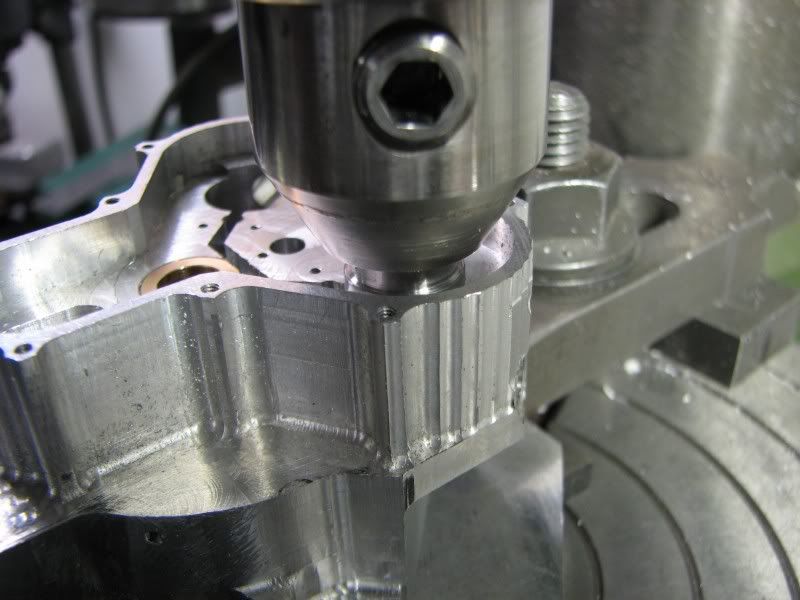
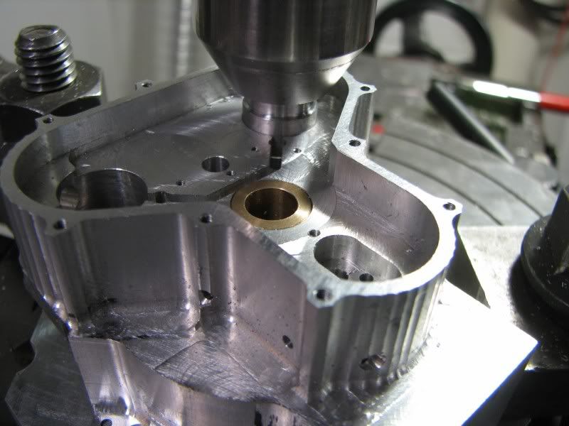
I then cleaned everything up and started setting up for the cam boss radii. I had to make another set up plug for the cam holes as they are .562 diameter. The same procedure was used. Center table, locate part, clamp and cut. I was using a .25 diameter cutter for all the fillets so I first cut the largest area with a long 4 flute and then went back with a ball mill and stepped around the lifter bosses. They will late be cleaned up by hand.
BX.jpg

BY.jpg

BZ.jpg
 
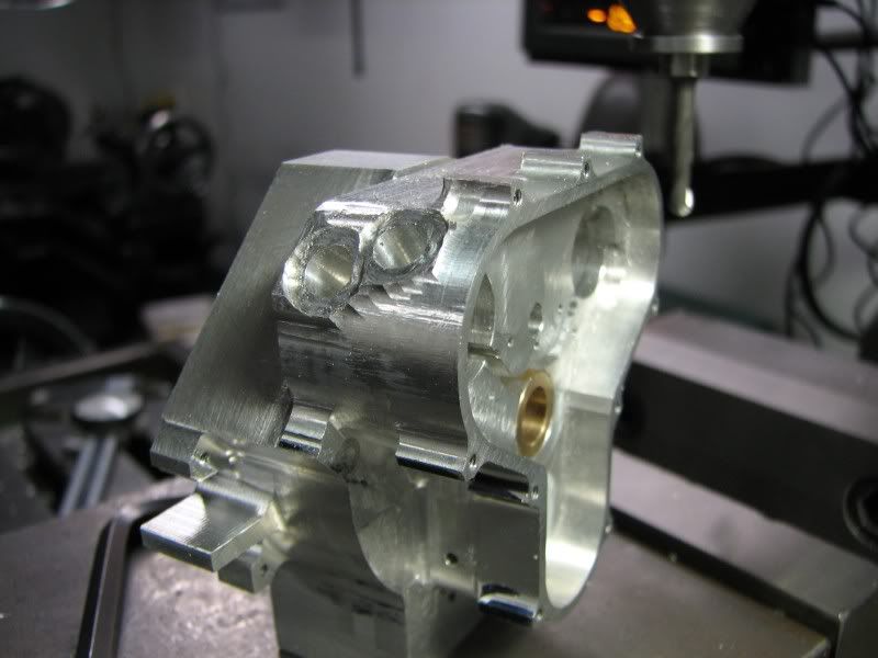
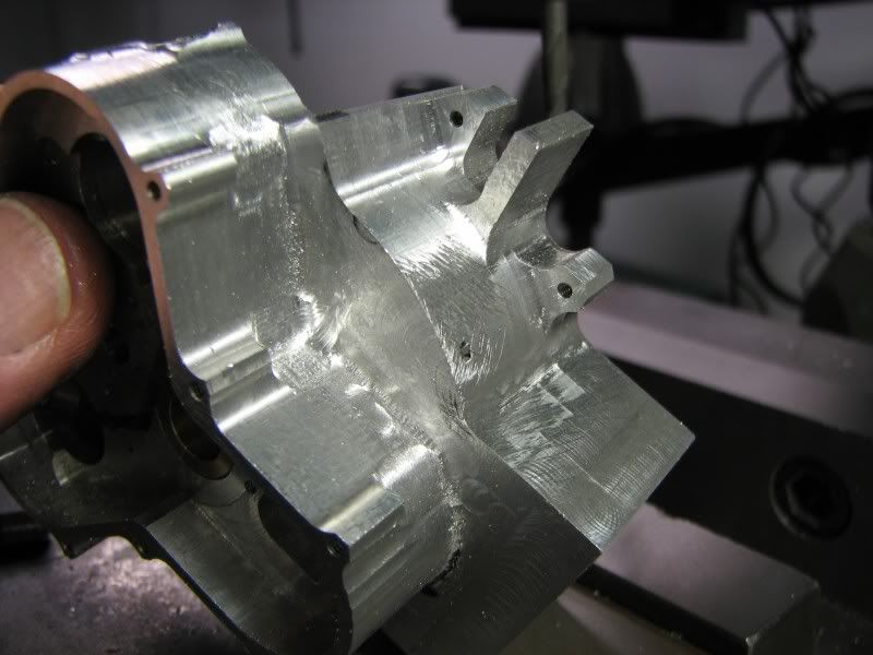
The last two pictures for today show the cam cover bolt bosses cut back and a little bit of filing that I did between surfaces. Just a little bit more machining and then the hand work starts.
CA.jpg

CB-1.jpg
 
You amaze George. I guess you'll be spending time now with the files.

Tony
 
That's a lot of work already, George, and well done!
It's good to see your hands or fingers in the shots now and then to be reminded of the size of the pieces you're working on.

Thanks for the write up and pictures!


Dean


Before I saw the thumb in the picture I didn't realize how small this is!!

Amazing!!! woohoo1 woohoo1 woohoo1

I can only aspire to such work.

Ron
 
As always, George, very nice.
Gail in NM
 
there aren't words to comment...
I silently admire such a high level of craftsmanship
and hopefully I will learn

 
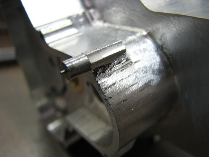
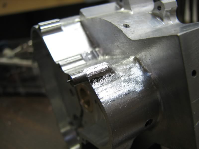
Sorry for the deleted pictures. I was loading the new ones and thought that the old ones were doubles. Anyway on with today's work. The first picture shows the pin gauge that I use for cutting down the bosses. I screw it into the tapped hole and then grind and file till I match it. In this first picture you can see the boss as it was roughed from the initial machining. I probably could have left a little more stock but it was o.k.
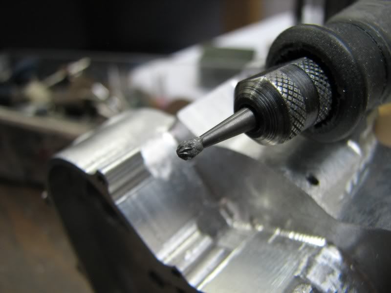
The next picture shows the boss after grinding with the burr which is shown in the next shot.
CC.jpg

CD.jpg

CE.jpg
 
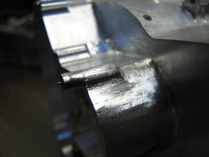
The next picture shows the boss after filing. I support the file on the bushing to keep the surface flat. I work around the boss until I get the radius even. The next picture shows the boss after a little bit of cleanup with small mounted stone, about a medium grade grit. (brown)
CF.jpg

CG.jpg
 
The final three pictures for today show the gear side crankcase with all the filing and sanding done on the bosses and surfaces surrounding the gear case. Aluminum is so unforgiving with tool marks. The slightest little mark and it shows up from a mile away. It requires a lot of filing and sanding with a piece of emery wrapped around a small flat stick to get into the tight spots. I finished getting the tree decorated for the wife so I have most of tomorrow to finish up the bolt bosses that hold the cases together. The other side doesn't have near the finishing work as this one so I might even get it finished also. The only machining remaining is to bore for the cylinder flanges and put the fins on the oil pan.
gbritnell
CH.jpg

CJ.jpg

CK.jpg


I know they're now out of sequence but here's the two pictures that I removed.
gbritnell
CA.jpg

CB.jpg
 
Great craftsmanship, George!
It takes a lot of practice to know when to stop when it comes to forming things like the thread bosses, and breaking sharp edges on the crank case.
What an enormous amount of work you've done already.
Very nice, indeed.

Dean
 
Wow, George that's really trick! :bow:

The case is coming along real nice. With the machine marks vanishing it's starting to look like a cast aluminum crank case. I newer imagined that was the look you heading for.

Can't wait to see more!

-MB

 
I too did not realize just how diminutive that engine is. Wow. I am pretty much awestruck. Thanks for taking the time to show us all the detail on how some of those processes go.

 
Amazing work, looks just like a casting but with a much better finish!

Well done.
 
Wow George.
This is a great example of what one can do with their hands and some patience.
 
zeeprogrammer said:
Wow George.
This is a great example of what one can do with their hands and some patience.

Couldn't say it any better! :bow:

You can tell a man by their hands and their chips....George....you work!
:bow:
 
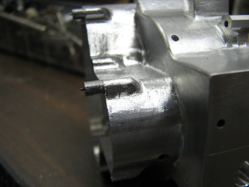
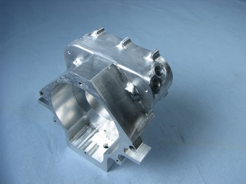
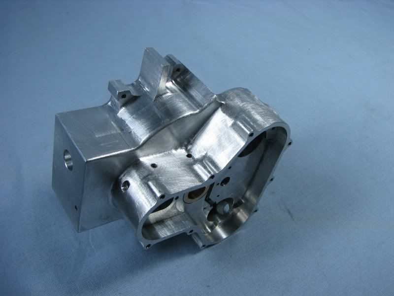
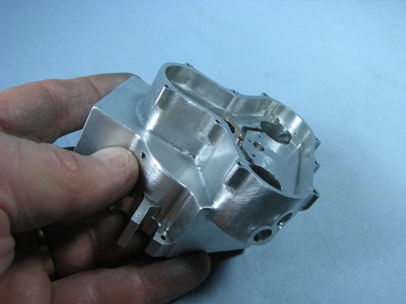
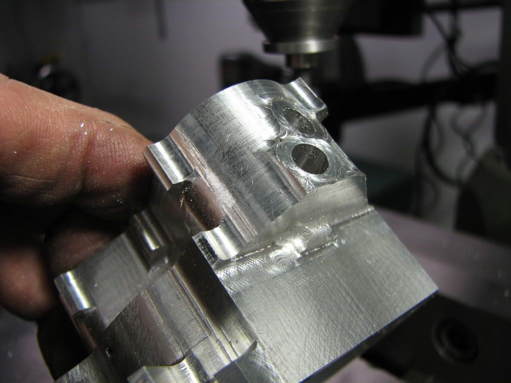
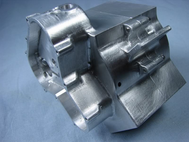
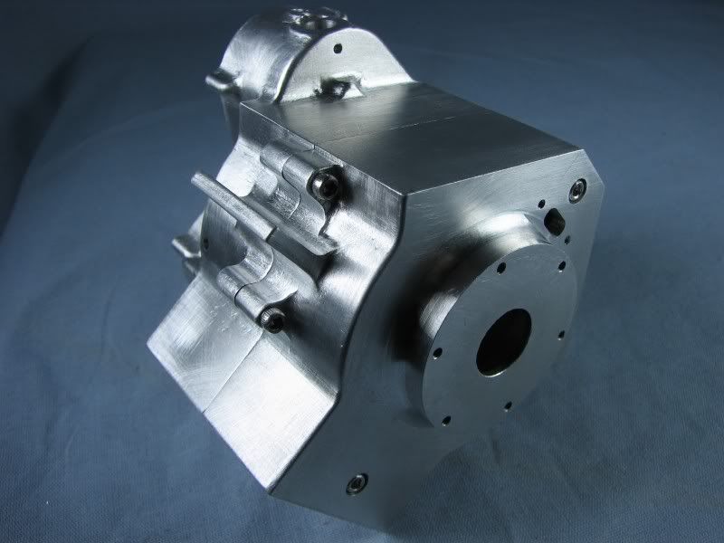
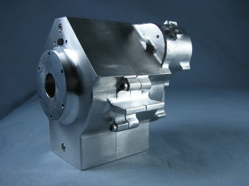
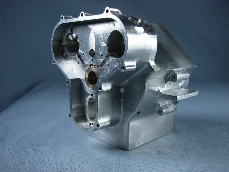
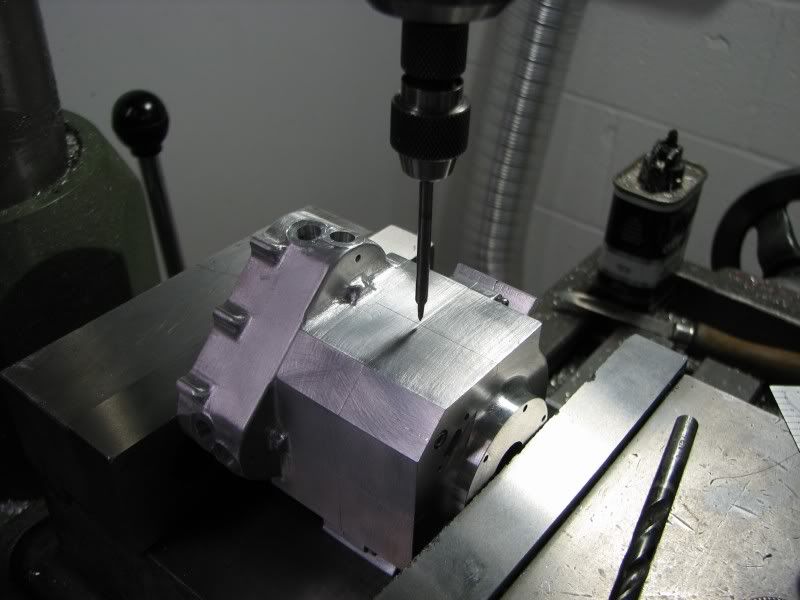
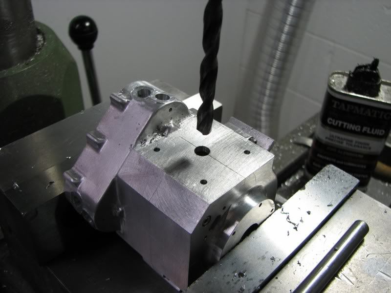
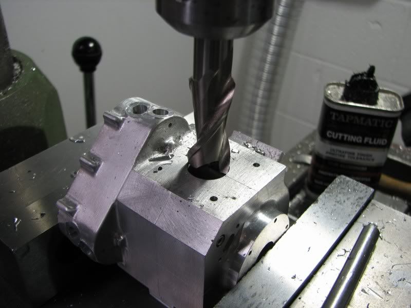
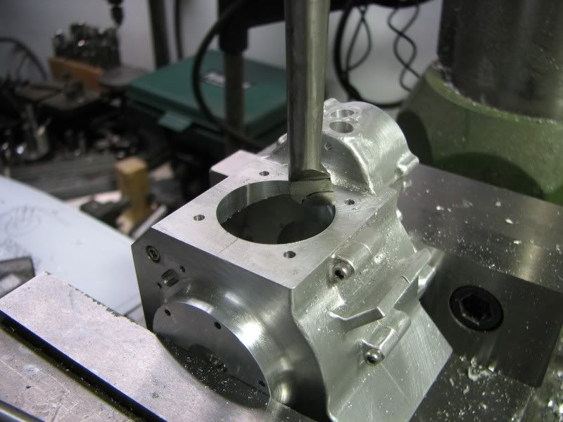
I got more done than I had hoped for. I finished up the large bolt bosses around the perimeter of the case, cleaned up the tool marks and polished it up. I used the same procedure for the large bosses. I made up a filing plug, screwed it in the hole and ground and filed until the boss matched the plug. I then drilled the threaded holes out of the off side, they had been tapped so that I could mount it to the fixture plate for machining. The two halves were then bolted together and the surfaces were matched. A final lick with emery and the hand work is done. The assembly then went back to the layout plate to get the centerlines marked on. From there into the mill vise where I calculated how much head space I would need to get the several tools in without having to change the height, hopefully. First the centerlines were picked up with a wiggler. Next the cylinder mounting holes were drilled. After that I used a progression of end mills to get the bore hole up to 1.00 diameter. Finally I put my boring head in and took the hole out to size, 1.125 diameter. This Enco mill isn't the best machine in the world for boring but I helped it out the first time I took the spindle out for cleaning, greasing and readjusting. While the spindle was out I drilled and tapped two 5/16 holes on either side of the spindle hole as high as I could above the locking clamp. Upon assembly I inserted 2 brass plugs followed by set screws. When I'm boring I keep them snugged up a little that way I don't get as much movement out of the spindle. Necessity is still the mother of invention. OK, enough chatter, I'm sure you want to see some pictures. The first four shots are the crankcase with all the bosses finished, the tool marks cleaned up and everything polished up with emery paper.
CO.jpg

CP.jpg

CQ.jpg

CS.jpg

 
The next four pictures show the progression of the machining for the cylinder flange, wiggle centers, drill holes, used successively larger end mills and finally bore to size. After that the other surface was set up and all the steps were repeated.
CT.jpg

CU.jpg

CV.jpg

CW.jpg
 

Latest posts

Back
Top