TB4 Build

Home Model Engine Machinist Forum

Help Support Home Model Engine Machinist Forum:

This site may earn a commission from merchant affiliate links, including eBay, Amazon, and others.
and a couple shots of my piston con rods flat metal with holes and tapered with a file.
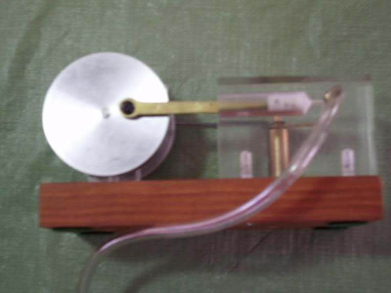
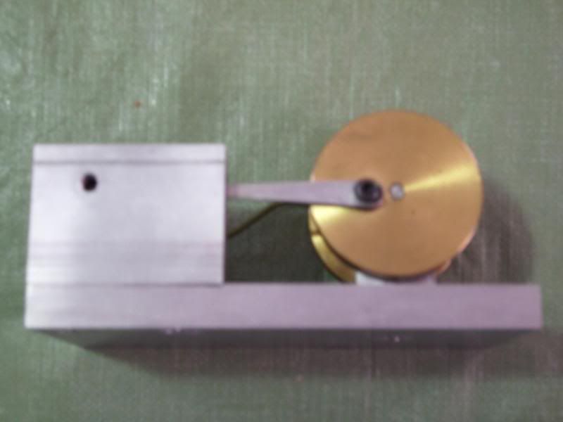

1clairesideB.jpg


1runnerside.jpg

Tin
 
Perfect alignment is not needed for this engine but we do need to be careful with parts rubbing and interfering with each other.
And a note jumping ahead you will need a little locktite for assembly or one or another screw will back out and it will fall apart.
Also we will need to feed this thing I made barb connectors from brass hex. I can provide details. I generally use aquarium hose to run air. This engine will run in either direction . it is just a matter of how the timing is set.
Tin
 
Tin Falcon said:
Also we will need to feed this thing I made barb connectors from brass hex. I can provide details. I generally use aquarium hose to run air. This engine will run in either direction . it is just a matter of how the timing is set.

I posted a while back about possible threads in the outboard side of the block. Let me know and i will modify
 
You don't need barbs at all if you use the silicone aquarium tubing. It's "sticky" enough to grip a 3/16" smooth brass fitting at the low pressures needed for these small engines. In addition, a 3/16" rod can be directly threaded 10-32 - no need to turn it down.

This is the arrangement I use for all my small engines and it works well.
 
Is everyone clear now ?? do you need any more help or info??
Tin
 
I have finished (well almost) the drawings ... I have several requests:

The axle should be 2.000" long ....

Jeff ... one of the screws the .130" should be .380" the other screw should be .135".

With these changes the rods will line up very good.

I will go over the reasons why a little later as we are about to leave for a while.

And have a few more issues (minor) ...


Thanks,

Pat H
 
How do folks want to handle shipping parts .
Option 1 round robing send 1 set of parts to each of the the other folks send out 4-5 small packages receive same.
or sent all parts to one person and that person makes all kits and ships them to team members.
Tin
 
Tin,

I also agree ...ship to each member.

Also ... thanks a bunch for the photos they where a great help. :)

Plan to post the drawing in the next couple of hours ... I have to figure out how to do that. ???
Alone with the reasons for the drawing change request.


Pat H.
 
Finally able to get the drawings posted. :big:

The first drawing is just what the assembly will look like in the Trimetric view.

For the Connecting Rod I'm using 1/16" brass material with a .201" hole for the Fly Wheel and a .033" hole for the piston.
The Valve Push Rod is a two piece assembly ... the rod portion is a .094" rod that will be screwed into the a block that
attaches to the Fly Wheel. (Note that the drawing shows the Valve Push Rod parallel to the Base ... actually it will be at an angle.)
This will be the adjustment to position the valve at mid-stroke, when the piston is at TDC. The top of the Rocker Arm will
be near the center line of the Fly Wheels. The Valve rod will have to be be bent lightly.

Runner Steam Engine TB4 asm.JPG


The next drawing is the top view and shows the dimensions that I have asked to be changed.

So that other parts do not need any changes (Base, Bearing Carrier and Block) the Axle needs to be 2.000",
this gives a nice symmetrical look for the Fly Wheels and Bearing Carrier. The Valve Push Rod will only stick out a little.


Runner Steam Engine TB4 drw.JPG


Concerns:

With the Piston at TDC there is a gap of about .027" to the end of cylinder hole (1.252") ... is that okay ... too much or too little? This can
be changed by moving the .033" hole ... easy to do.

The holes for the two rods on the Rocker Arm might be too big ... not sure will have to wait and see.


One possible solution to these variables would be to send me one set of parts, then I would make my parts based on what I got.
Once I made them and get the unit to function I would then send my made parts out to each of you.

What do you think?

Later,


Pat H.


Path said:

For the Connecting Rod I'm using 1/16" brass material with a .201" hole for the Fly Wheel and a .033" hole for the piston.


If we are going to use brass instead of wire for the rod, could we increase the hole size to avoid breaking bits? I have .0625 drill rod. I have to drill .375 deep so it could save me a few drill bits.

Let me know

 
Steve,

Sure .. that's a great idea. The width of the Connecting Rod at the piston will .140" so that
leaves .038" on each side ... should be no problem. :)

So I will change the hole size from .033" (#66 drill) to .0635" (#52 drill) for the Piston Wrist Pin.

Pat H.

 
Path said:
Steve,

Sure .. that's a great idea. The width of the Connecting Rod at the piston will .140" so that
leaves .038" on each side ... should be no problem. :)

So I will change the hole size from .033" (#66 drill) to .0635" (#52 drill) for the Piston Wrist Pin.

Pat H.


You are the man!! Just be sure we have enough room at the head end of the rod. If not we can shorten the rod a bit and I can also move the hole back a few thou so GOOD DEAL!
 
Well that's it for me folks!!

My parts are done. I'm going to leave the cylinder block alone as far as the air fitting goes. That one is up to the individual. The pistons are finished and the wrist pins are started in the hole they get pressed in. I figured if I press them in the hole, they wont get lost in the mail. I'm going to send them out as soon as I get a mailing list.

Cheers!

Steve Huck
 
I have almost got the bearing block finnished as well just need to drill some holes
and tap one.

How is everyone else doing with thier stuff???
 
This is great ... :) :)

Should I PM my address so that you can start sending parts?

Pat H.
 

Latest posts

Back
Top