Potty Popcorn Engine

Home Model Engine Machinist Forum

Help Support Home Model Engine Machinist Forum:

This site may earn a commission from merchant affiliate links, including eBay, Amazon, and others.
Looking very good Brian great Job :bow:

Stew
 
Stew---Based on your original drawing of the crosshead guide, a 12.5mm crank throw, a 68 c/c piston rod, a 5mm thick piston, and a 34mm long cylinder, this is the way the centers work out. It looks good and everything appears to clear, but the crosshead comes out of the crosshead guide by about 4mm at end of stroke. Is this acceptable?
POPCORNASSEMBLY-2.jpg


View attachment POPCORN ASSEMBLY.PDF
 
Hi Brian

As I've made it the cross head will be within the guide I made a mistake with the hole depth for some reason or other probably a maths error by me.

But I wouldn't think it would mater that much it still got plenty of support and it also gives the connecting rod a bit of clearance when its at mid stroke.

That crank/rod clearance looks OK if it is a problem I can always file a small flat on the connecting rod and blend things in.

Bin working on the rod tonight whilst its cool, its bin a scorcher today in the UK.

The drawing realy are looking great.

Stew

 
Okay Stew---I've bothered you enough. I have your Popcorn engine fully modelled now, using metric dimensions everywhere except for bolt sizes which are practically the same diameter anyways, and for shaft sizes, where I have standardized on 1/8", 3/16", and 5/16". Unfortunately there are no British Imperial size shafting that corresponds to 4mm, so I bumped the 4mm shafting up to 3/16" which is 4.76mm. I used a 1/2" bore because I have a 1/2" reamer, and the bore inside the crosshead guide (and the crosshead itself) got bumped to 5/8" because I have a 5/8" reamer. Thank you for your patience. I will wait now to see your completed build, and the next time I feel an urge to do some work in my little shop I will probably build a clone of your engine with British Imperial dimensions. One nice thing about the computer is that I can model everything in metric, then have it generate drawings with all of the metric converted (Hard conversion) to British Imperial to 3 decimel places. Thanks again.----Brian
POPCORNASSEMBLY-3.jpg
 
Stew,
I have been watching this with great interest especially how you attached the frame to the cylinder head. What type of fastner is used for the joint?

The engine looks very much like the early Shay cylinders.

Dan
 
Hi Dan

Its just a push fit onto the front of the cylinder cover, the front of the frame is bolted to the crank saft bearing frame, holding it in place.

The cylinder cover is bolted to the cylinder with M3 bolts.

Hope this makes sence.

Thanks for you're interest.

Stew

 
On with the connecting Rod:-

Cut a length of mild steel to length and put a sacrificial centre in each end.

Then with the compound set over at 2.5 deg for the barrel shape

131_0704.jpg


Then onto the mill and mill flats on the ends had to use thin parallels for the barrel to fit in.

131_0707.jpg


Drill holes for the bearings

131_0711.jpg


This is what you get

131_0714.jpg


Cut the centers off then using filing buttons shape the eye at one end to fit in cross head.

131_0719.jpg


It's coming on next job crank shaft bearing supports.

131_0722.jpg


Stew
 
Well it bin a bit of a frustrating day, made a good start on the bearing stands, then my DRO jammed up the read out was just saying the same numbers switched it off and on fiddled with it went and had a cupa, came back switched it on and it was OK 1/2 hr later same thing, had a fiddle left it alone for at bit switched it on all OK 1/2 hr later same thing.

Decided to leave it until the morning when its cooler, its bin darn hot her in the UK, but you would have thought it could handle a hot UK day, any of you guys experienced similar problems ???

Stew
 
How hot has it been Stew? We are into our early fall "normal" here which is about 20C daytime highs (about 70 degrees F), cooling off to about 40F at night. You are in England, aren't you?
 
Brian Rupnow said:
Unfortunately there are no British Imperial size shafting that corresponds to 4mm, so I bumped the 4mm shafting up to 3/16" which is 4.76mm.

Brian, what about 5/32" rod easily available here so I would have though it would be the same for you. Infact I've put an M4 thread onto 5/32" material several times as its often easier to buy shorter lengths of imperial than metric from our model engineering suppliers

Oh and 30deg C in my shed when I got home today, too hot for engineering.

J
 
Maybe you are right, Jason, but I just called my metal supplier when I seen your message, and they don't carry it. I might be able to get it on "special order" but its not worth the bother when its so easy to modify a plan.---And isn't that unusually hot for your part of the world?
 
I'm surprized by that, we can readily get 5/32" in brass, stainless steel, drill rod, mild steel including square and hex and that from a country that went metric years ago ::)

Yes its a lot hotter than usual, just watching the weather forcast and its quite likely that tomorrow could be the hottest October 1st since 1985 as it's expected to reach 29deg C. Plants don't know whats happening, they have their fall leaves but are comming into flower. But just give it a coupel of weeks and we will probably have a foot of snow :(

J
 
Brian Rupnow said:
How hot has it been Stew? We are into our early fall "normal" here which is about 20C daytime highs (about 70 degrees F), cooling off to about 40F at night. You are in England, aren't you?

Hi Brian

Yes I'm in England:-CreweCrewe, Cheshire about 50 miles South East of Manchester, my shop must have bin about 30 this afternoon as well, the tin roof doesn't help it's unseasonably hot normal temp for Oct 10 - 15

I never thanked you properly for your wonderful 3D model of the engine its awesome work.

Even tough I draw in metric I often use imperial sizes as I've got a lot of imperial kit, I made the cylinder 1/2" bore and used a 5/8" reamer on the cross head guide. I tend to change things as I go along, using what kit and material I have at hand, and if I see something I don't like the look of I change that as well. Thats what so great about this game drawings are not contractual like in industry, you're only constrained by the limits of your imagination and you ingenuity.

Thanks again

Stew
 
Stew--I do the same exact thing. First I design something. I check clearances, fits, concentricity of mating holes, the models and drawings are flawless. (To me anyways). Then I start to machine it---oh, Damn---I haven't got a reamer/cutter/drill/whatever the right size!! Do I go across town to the toolshops and buy the right sized peice of kit?--Of course not!!! I change the drawing to reflect what I have in my shop right NOW! The drawings I post at the end of one of my projects have sometimes "morphed" into something considerably different than what was initially posted. Thats why I warn people right up front--"Don't save these initial drawings---Wait for the .pdf files at the end of the job."
 
Got up this morning bright and early nice and cool in the shed and the DRO worked without a hitch, I think the problem must be temperature related, but the UK is not known for its high temperatures, you would have thought it would work at temperatures greater than 30 C.

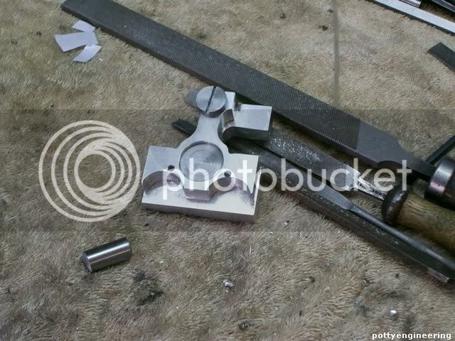
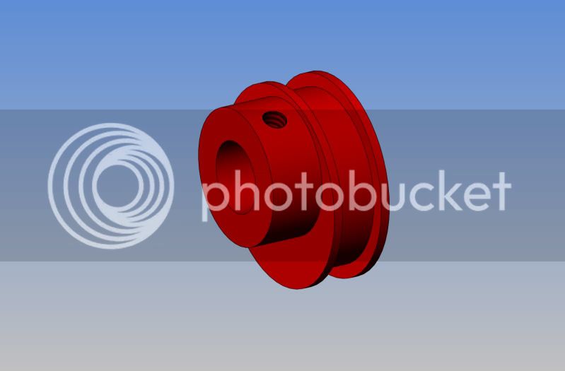
The bearing support is a tail of a cleaver idea coming apart.

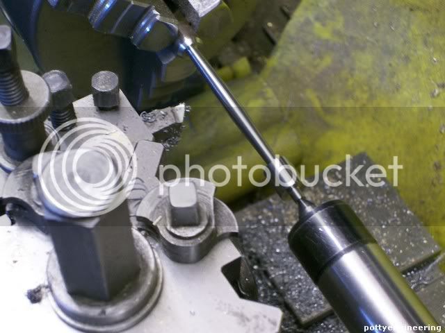
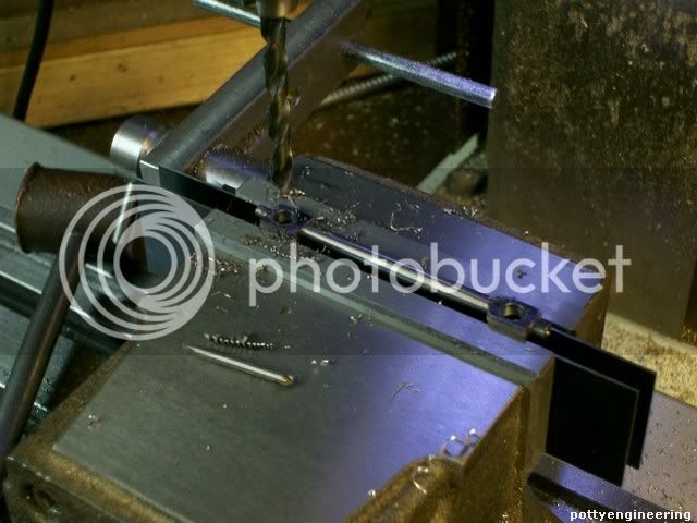
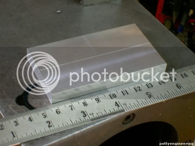
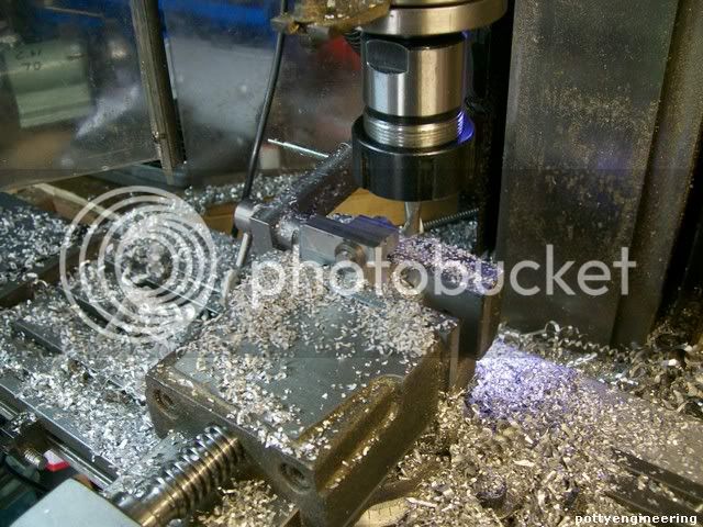
Squared up A piece of jig plate and fly cut it to the correct thickness.

131_0723.jpg


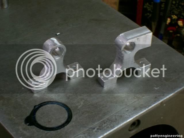
My idea was to make both out of the same piece, as mirror images, first thing I realized was that my co-ordinates on the drawing were all wrong, I seemed to have snapped onto the wrong point when doing the dimensions and they are a mile out so I had to go back on the computer and correct the drawing.

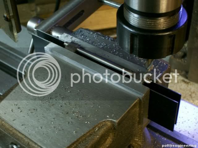
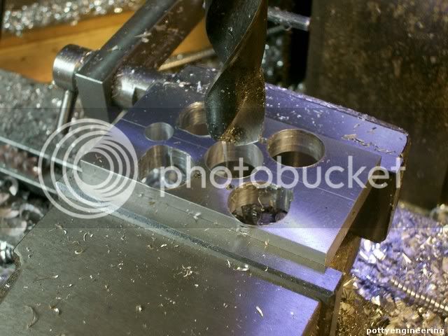
Drilling the corner holes out went fine.

131_0726.jpg


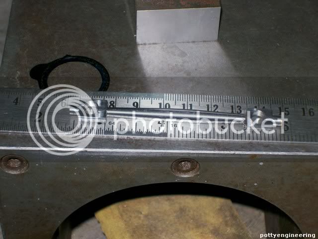
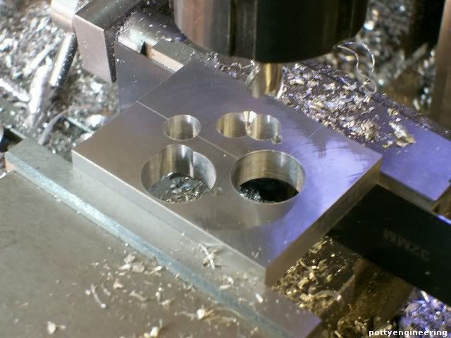
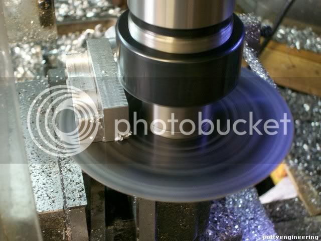
Spot the deliberate mistake:-the two supports are not identical one has an extension for the cross head guide to fasten to, I went and put a 20mm drill right through it. :'(

I out cleavered my self with that one. ::)

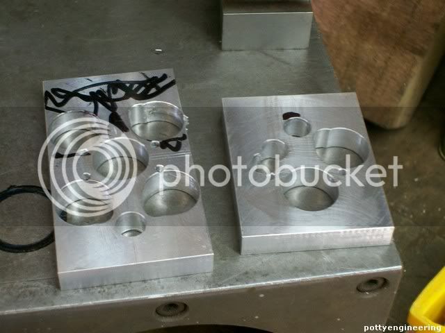
Ok make another one, just a single this time and leave the support untouched.

131_0727.jpg


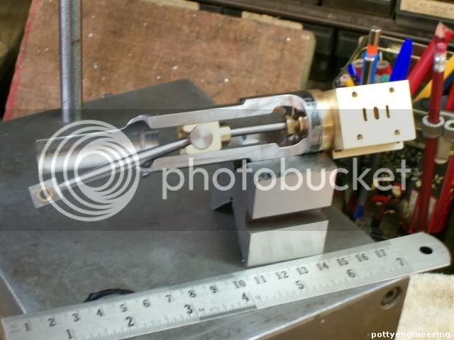
Her they are waiting to have the rest of the unwanted bits chewed away.

131_0732.jpg


Stew
 
Finished of the supports.

I stuck the two supports together with two way tape, and made a couple of plugs to go in the holes to stop things moving around, I also made a filing button, for the top eye.

It was then a matter of nibbling material away from where its wasn't wanted.

In the mill

131_0733.jpg


And with files.

131_0735.jpg


And used a slitting saw to cut through the base, and cleaned across the base with a fly cutter, I'd plugged the bearing hole together, so the crank shaft will sit perfectly level.

131_0736.jpg


A bit more work with files and they are looking something near, I'll tidy them up a bit more but has they are going to be painted they won't need polishing.

131_0741.jpg


Stew
 
Looks very good Stew. I made the same stands and ended up with one about.7mm taller than the other!!! :( :( :( I am going to cheat and loctite a .7mm fill plate to the underside of the short one). I am not posting any progress on mine, just working away in the background. One thing I noticed this morning while building the cam.--On previous cams I have built, the hub was offset to one side with the set screw in the offset part. This let me "play with" the valve timing untill the engine worked at its best. This cam is going to be a beast to adjust as it requires dismantling the eccentric strap to get at the set screw.
 
One thing I noticed this morning while building the cam.--On previous cams I have built, the hub was offset to one side with the set screw in the offset part. This let me "play with" the valve timing until the engine worked at its best. This cam is going to be a beast to adjust as it requires dismantling the eccentric strap to get at the set screw.

Thats very true Brian, they need to be on the other side, When I built the over crank I had problem tapping the cam through the thicker section, the tap didn't reach far enough, so I moved it 180 to come through the thinner section:-as you said, this makes it difficult the set the timing, for some reason I drew the popcorn up with the set screw coming through the thinner section, it could quite easily come through the thicker section as the cam is a lot smaller.

Another problem I had with the over crank cam was that I used M2 grub screws these were just not man enough for the job, the cam kept slipping so I had to tap them out bigger to M3.

Things will be slowing down on this build over the next couple of weeks due to family commitments, which is a bit frustrating as it's getting so close to a test run, but I will be getting the pleasure of seeing my grandchildren.

Stew
 
Stew--I meant offset to the outside like this so that the grub screw was always accesable, not covered by the eccentric strap. And yes, grandchildren are great. Wife and I had two of ours over today for lunch and a "visit" The seven year old is really proud of her reading skills, and wants to read to us, the four year old can't read but fakes it-----no way her older sister is going to get all the attention!!!
POPCORNECCENTRIC.jpg
 
I usually put the grub screw in at 180° to that - on the theory that it is a little less visible with the eccentric wall beside it.

 
Back
Top