Potty Popcorn Engine

Home Model Engine Machinist Forum

Help Support Home Model Engine Machinist Forum:

This site may earn a commission from merchant affiliate links, including eBay, Amazon, and others.
I'm liking the way that crosshead slide came out. The whole assembly, including connecting rod, is very nicely done. I like the way the con rod connects to the crosshead. Wouldn't have thought of that on my own... :-[

Chuck
 
Thanks Tel, Chuck, Brian

That is certainly a better way of fixing the cam, there is plenty of room on the crank to do it this way with this engine, when room is tight between the crank as in a loco or in my over crank engine, you have to put the screw under the eccentric sheath. I think I will adopt this better method on the popcorn.

Thanks for your input guys.

Stew
 
This will be the last post on this job, for over a week going to have a house full of kids and grand kids.

I decided to make the crank shaft with a disc throw, quite a few of the popcorn engines I've seen [ics of have this set up so thought I'd give it a go.

With a chunk of steel in the chuck turn the od and centre drill, then centre it on the mill a off set it by the throw and drill with a number drill just below the size of the crank pin so its a tight fit. One thing they do with this type of crank is maching out a curve oposite the crank pin to balance the crank so using the rotary table mill a 60 deg curve.

131_0745.jpg


131_0749.jpg


Then still in the chuck back to the lathe and drill out for the crank shaft again using a number drill so that its a tight fit.

Then skim it off to correct thickness, the material I'm using is tool steel used to make draw dies from, high carbon with bits and bobs of other things in it, I'm familiar with this steel and know it turn well with high speed tools, but it produces wicked razor sharp snakes of swarf.

131_0752.jpg


Glue the shaft and pin in

131_0754.jpg


Turn up the main bearings and glue them in.

131_0757.jpg


Time for a few hows it looking shots.

131_0758.jpg


131_0760.jpg


Not bad.

Stew


.
 

Stew, The engine is coming along great. Your drawings and build pictures should get me
moving on my own.

Regards,
Mike
 

Very nice work you are doing Stew.

It is looking great!

 
Very nice work, Stew. It's looking fabulous. I don't mean this as a criticism, just a suggestion and this may not be an option... Do you think the engine might look better with a larger flywheel?

Chuck
 
Thanks Chaps.

Chuck:- I see what you mean the cylinder looks slightly over scale, a bigger fly wheel would componsate for that.

Dunbar1.jpg


131_0758.jpg


Stew
 
I have to agree with Chuck on this one Stew, and also comment that in comparing the disc crank and the usual one, I prefer the latter, although far be it from me to criticize the master.

Are you exhibiting your overcrank engine at the model engineering exhibition in Warwick on the 14th, I hope you are as I would love to see it.

Cheers Les :bow:
 
Hi Lesmo

No I'm nit at Warwick, but it will be at Sandown in December.

Stew
 
Re my previous comment which my better half later read. She said that it was not polite to say that I preferred the other engine to yours, which was not at all what I meant, but I guess it could be taken that way. I was observing that a disc crank does not convey the sense of fluid movement nearly so well as does a conventional crank.

Cheers Stew, see you at Sandown if we are not up to the gills in snow by then.

Les
 
Lesmo said:
Re my previous comment which my better half later read. She said that it was not polite to say that I preferred the other engine to yours, which was not at all what I meant, but I guess it could be taken that way. I was observing that a disc crank does not convey the sense of fluid movement nearly so well as does a conventional crank.
Cheers Stew, see you at Sandown if we are not up to the gills in snow by then.
Les

Don't worry about it Les all comment are greatly received.

I'm still thinking about tghat crank myself, easy to change it back.

My boss sometimes sensors my posts, by saying that's a bit ladish/sexist isn't it, or that's spelt wrong, that serves me right for marrying a school teacher:- being bossy comes with the job.

Hope she doesn't see this :big:

Stew


Well back off holiday, and got another part ticked off:- the eccentric.

Decided to use the design that Brian suggested.

Using a bit of mild steel bar first turn a 5mm wide groove to 20mm dia, and put a small centre drill into the end

131_0762.jpg


Then over onto the mill and centre under the spindle.

Off set the mill to the throw of the eccentric and put in another small centre.

With a independent four jaw in the lathe and using a woble bar get the off set centre running true.

131_0768.jpg


Put a 7.5mm drill through followed by a 8mm reamer.

Back in the selve centring chuck turn a little boss to take the fixing grub screw, and part off

131_0775.jpg


Set up in the mill a drill and tap M3 for the grub screw.

131_0776.jpg


Thats that one done.

131_0777.jpg


Stew

 
Hello Stew, I've been following along and must say it is/has been a delight. That crosshead guide still astounds (scares the crap out of) me. It is interesting to note the visual differences that the engine has with the solid crank disk as opposed to the singular arm. The former gives a bit of flavor similar to the Tangye engines or perhaps a Corliss in a way. Overall, I like the looks either way and am really looking forward to seeing your creation run. Well done and I hope other things are going well for you.

BC1
Jim
 
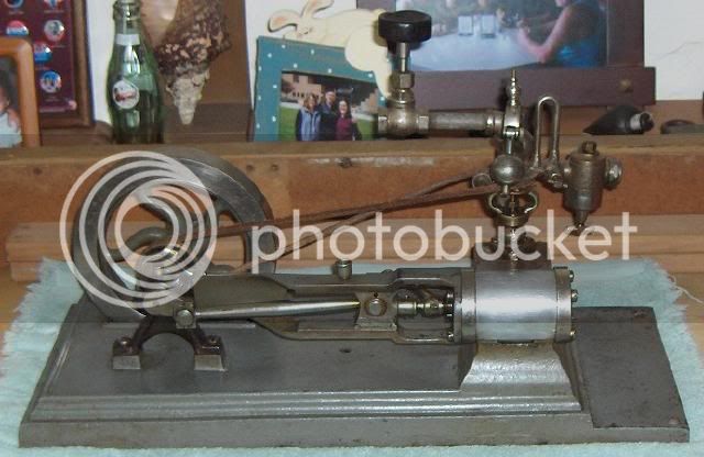
Hi Jim thanks for you comments, I've bin trying to get my-head round modeling a Corliss type valve gear, got lots of pics and videos of them from my visits to engine houses, still can't fathom a way ???.

Made the eccentric sleeve over the past couple of days, every time I make an eccentric sleeve I seem to end up making it a different way than the time before, I think that comes from making them from whatever material I have around at the time.

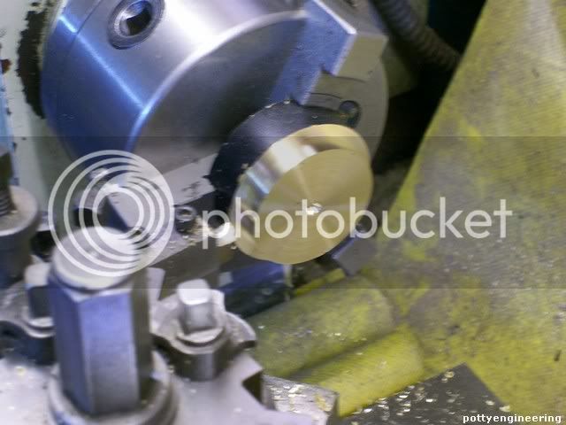
For this one I had a tub end from a bit of 45mm bar.

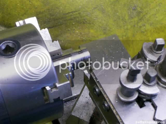
Started off in the lathe faced it off, centre drilled it and stuck a 1/2" drill down it.

131_0781.jpg


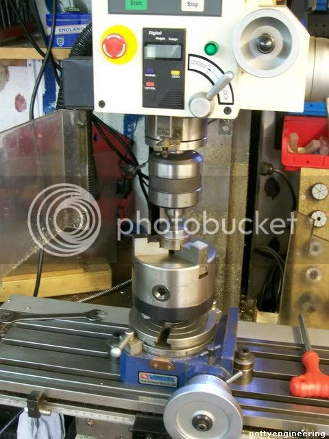
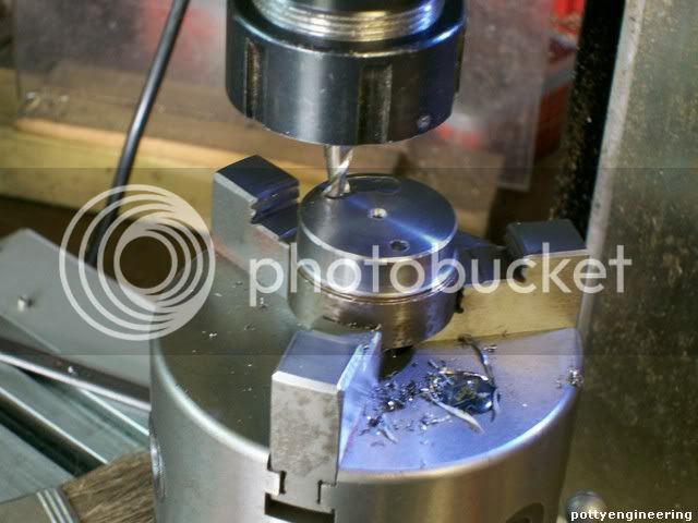
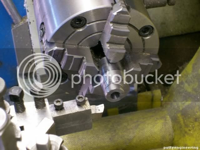
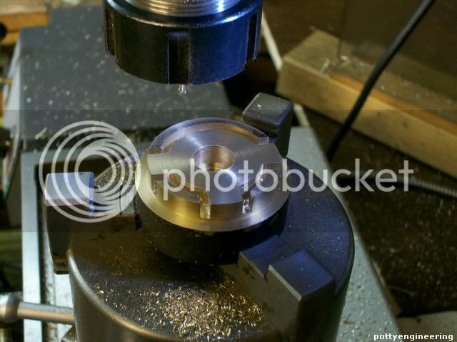
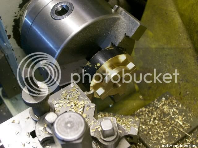
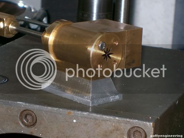
Then keeping it on the chuck transfered over to the RT centered under the mill spindle, and with a 3mm slot drill cut the shape out.

131_0785.jpg


Whilst I got it centered scribed a line across the middle, this will help set up for drilling a splitting.

131_0789.jpg


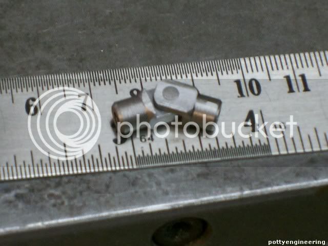
Then back over to the lathe things were a bit tight for room but managed to part it off:-still got enough of the stub of bar left for a flywheel sometime.

131_0790.jpg


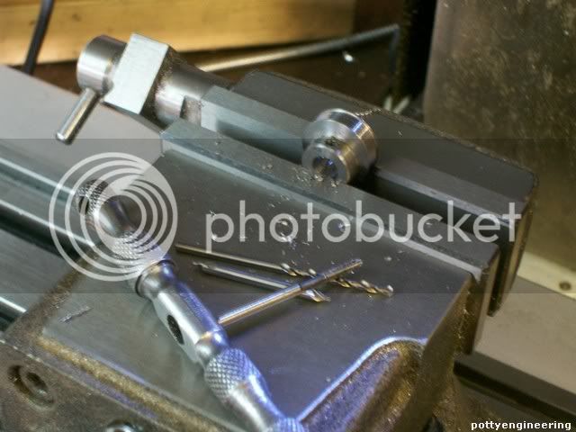
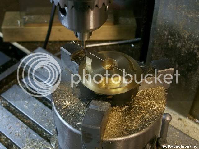
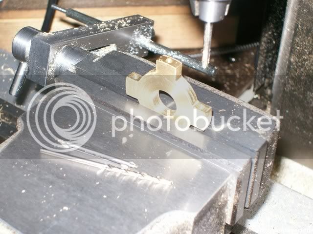
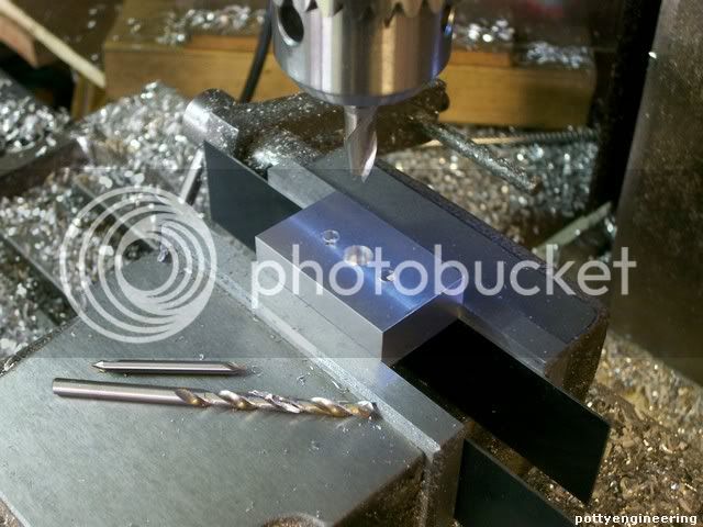
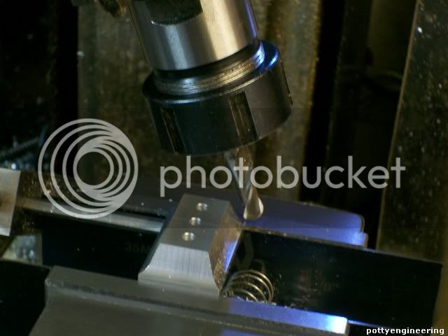
Then using the scribe marks lined it up level in the mill and drilled and tapped the holes.

131_0795.jpg


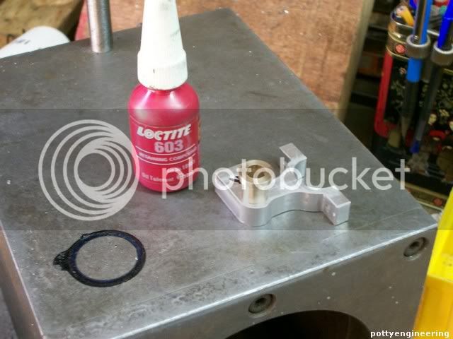
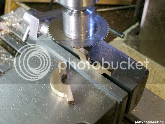
Then with a slitting saw cut it in half.

131_0803.jpg


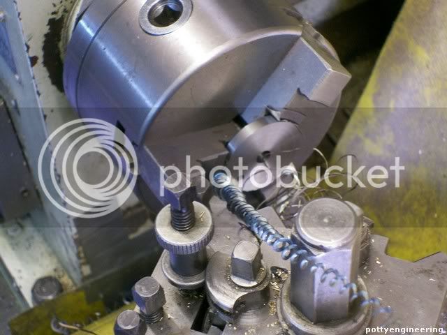
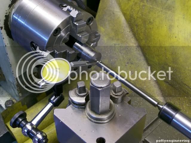
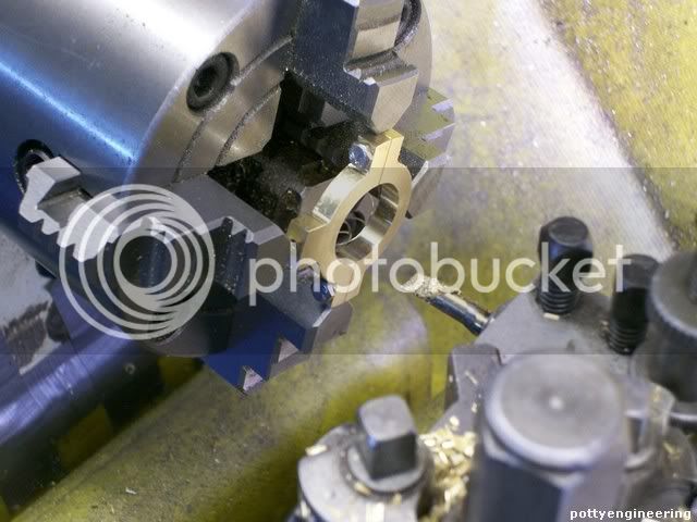
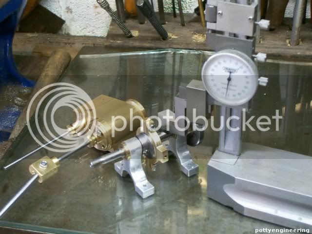
Then set it up in the four jaw, using my centre height gauge get the split on centre, its more important that you get the split centered than getting it exactly in the middle 90 deg from the split.

And bored it out for a good fit on the eccentric.

131_0804.jpg


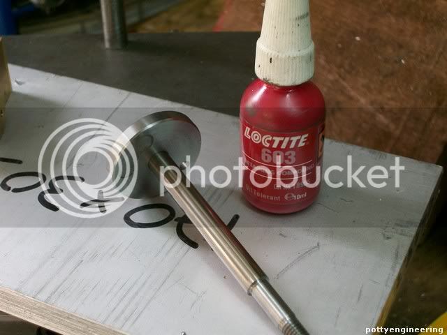
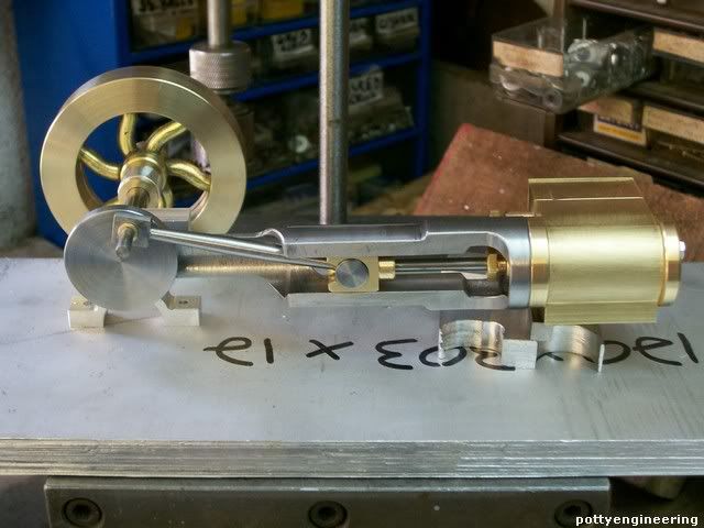
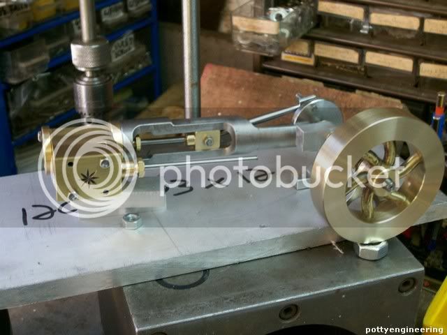
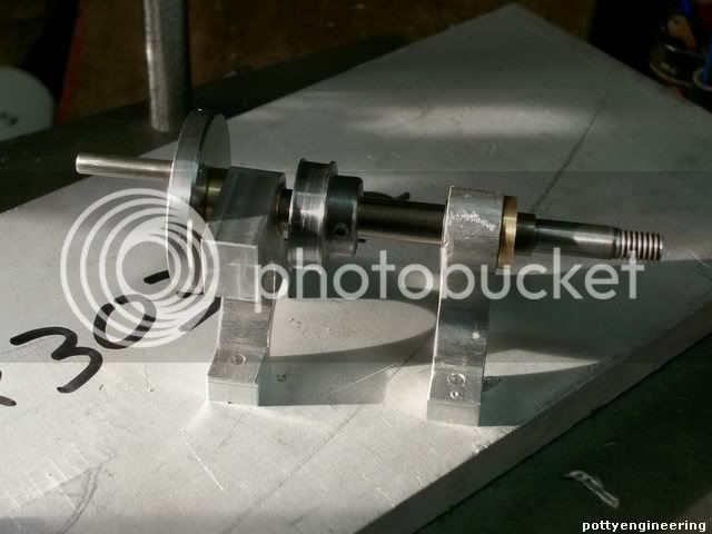
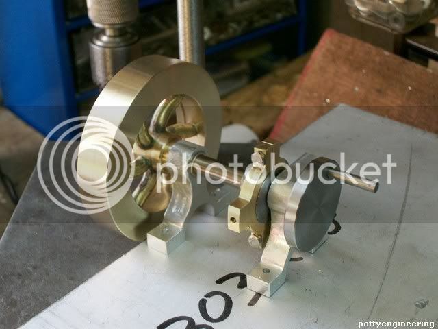
Her it is assembled.

131_0811.jpg


Stew
 
Moving on completed the base.

Measured the centre height to the crank shaft and the piston rods take one from the other and thats what the base needs to be made with mine it came spot on 14mm.

131_0812.jpg


Fly cut a chunk of ally square and to size.

Then marked out uts centre and mark a square to match the base of the cylinder.

Drilled the clamping holes

131_0814.jpg


Then with a 10mm dia ball nosed cutter and the mill head slewed over 20 deg, mill a nice flared foot, working to the lines marked.

131_0815.jpg


This is what it looks like.

131_0830.jpg


As an aside any one know whats going on with the madmodder site bin unable to log on for over 24 hrs now.

Stew


Another bit done the slide valve coupling.

131_0840.jpg


Not many more to do now.

Stew
 
Stew - I have been watching with pleasure as this build unfolds. It looks like you are about down to the final assembly. Don't forget to put the drive pulley for the governor on the shaft. ;D Looks like there is plenty of room for it.

Jerry
 
Thanks Jerry

I'm planning on fitting a Governor and a few other bells and wistles, you see pictures of Popcorn engines that look like they've got a Christmas tree growing out of them: they have bits of pipes sticking out every whare.

I'll concentrate on getting a running engine before I enbark on that part of the build though.

Stew
 

Latest posts

Back
Top