Questions regarding drilling small holes, and runout.

Home Model Engine Machinist Forum

Help Support Home Model Engine Machinist Forum:

This site may earn a commission from merchant affiliate links, including eBay, Amazon, and others.
Hi Pete, Guys,

For what I paid for the collet set, its not worth the hassle of returning them ! I did complain to the vendor, but simply got ignored.

Anyway FWIW I've since discovered that my mill spindle bearings are starting to fret. I have adjusted the preload a little but its not helped at all. I suspect that the bottom bearing is not quite square in the housing, because the fretting is mainly on one side of the taper. The other annoying thing is that there are no visible numbers on the bearing race on either side, which makes me a little concerned.
 
Cheval, I'm using my lathe, and that comfortably tops at 1200rpm. I manage with brass - of a certain grade, but the steel seemed "too hard" (Bright-drawn mild steel stock). So maybe I should have used hot rolled (Black) mild steel? Or anneal the steel I was using?
K2
 
Hi Steamchick, I got fed up at some point in time with the same problem, and I bought myself for really small work a TAIG lathe (aka Peatol and similar to Sherline) that I motorized to go to 24.000 revs. The first time, and many times thereafter, it was a joy to see really nice double chipstrings coming from a 0,5 mm drill in a steel arbor. In repairing arbors of clocks we first anneal the end by heating up till red with a simple cigarette lighter.
 
I have a Dremel type of tool. Goes to 16000rpm. but when I tried a 0.25mm drill bit in it the end simply flew off. - Maybe the collets were not perfectly centred? I have a small old lathe.. but the bearings are not that good so would expect it to self-destruct over 10,000rpm...I have had twills of swarf when drilling brass. Foolishly I just tried on a piece of steel the "right size" - not the right hardness... as I was attempting to machine the end down to 0.3m dia. for a jet pricker. When that didn't work I thought to drill with the 0.25mm drills I have and insert a wire...
I'll try again with "better" material.
(Stupid me! - Didn't follow my own advice of selecting "the Right material for the job"!).
K2
 
Yesterday morning I bought an EDM drill for 15000 $$$, just when I was about to pay, the alarm clock went off. :cool:
The pile of money was gone, so were the debt, the machine and the transportation issue.
(I do not need to drill small holes, but the spark trick, is fascinating)

p.s. Maybe if I win the lottery, but my work colleague pointed out that I do not play.
 
For real small work an optical xy stage might work. Not for milling, but for drilling I can imagine it can do the job.
xystage.jpg

They are not as expensive as they look, but it is only small travel.
 
Before I learned the hard way what I finally understand now. Drilling holes or even using a drill press has a few more complexity's than some think or that seem to be almost never brought up on forums like these. Since it is so seldom mentioned, my assumption is that most with these lighter weight drill presses don't understand there not all that accurate because of there design issues.

You can add all the accuracy you can afford with higher cost chucks, collets, X,Y tables etc. And maybe for small light weight parts with tiny drills, then obtaining fairly perpendicular holes to the part surfaces with the usual bench or floor standing consumer grade drill press's can be done if the table is properly trammed to be square to the spindle. But all of the usual bench mounted or the much larger floor standing models most of us can afford will have that massive and built in design and accuracy defect that's very tough to work around or even properly solve. That cantilevered casting the table is attached to which allows it to be moved up & down the column by hand or with a crank handle, gear and rack. My last light weight drill press weighed about 250 + lbs and came with a surprisingly accurate keyed chuck that was almost as good as my Albrecht chucks. It had 16 speeds with a 14" swing and 1 HP motor. All round it was actually a half decent machine for a home shop. And it was fairly smooth and quiet in all of the speeds at least for a single phase machine. It's drive belts were absolute junk so I replaced those. My standard practice is to first check the chuck run out and tram the table to the spindle. Since the chuck run out on it was so good and the table did check out as being ground within a few 10ths and had a heavy ribbed casting, I went a bit further and got the table to less than .0005" in X,Y over a 9" - 10" circle. But what I didn't properly understand at the time is that tramming any machine is still a static test, and it can't show what does happen to a machine once any of those dynamic working loads start being applied. But I started using it with drills from about 1/16" - 3/4" and large forstner drills for wood. Then I added a fairly heavy X,Y table since this was just before I bought my Bridgeport clone.


And that's when I started noticing my deeper holes were no longer 90 degrees to the part surface I was drilling, or through the part and where I wanted them on the parts bottom surface. It took awhile to figure out, but dial indicators don't lie if there of reasonable quality and set up properly. For anyone with one of these lighter weight bench or floor model drill presses who still assume there accurate over those longer hole lengths, your fooling yourself and 5 minutes with an indicator will prove it. Remove any vise etc off the table. Set up the indicators magnetic base so it's attached to the DP's rear column and the indicator tip on the outside top face of the table that's closest to you. Zero the indicator, then apply maybe 10-20 lbs of pressure with your fingers to that front top of the table. Depending on the weight and size of your own DP, you'll see at least .020" - .050" or more of table deflection. That cantilevered arm between the column and where the table is clamped to it simply can't resist those variable loads that are being applied to it well enough. Watch closely enough any Youtube vodeo where one of these light weight DRP's are being used with any larger drill diameters and you can actually see that table deflection happening. I've read in the past that to drill even a 1/2" hole in mild steel requires at the minimum at least 150 lbs of down feed pressure on the drill point before it's forced to cut instead of rub. Given the quill handle length on that larger drill press I had, I'd estimate that down feed number would be fairly accurate to possibly a bit on the conservative side. Adding larger/smaller, heavier/lighter part weights and/or the same for hold down or clamping methods to the table will also affect how much it will sag even before you start adding those variable amounts of down feed pressure each different drill size will have.

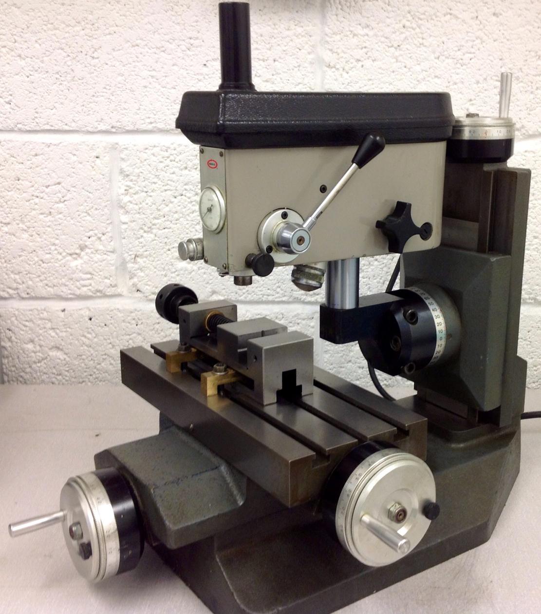
In general all of the more industrial level and much higher quality small DP's that do have the high rpm's for those tiny drills will almost always have the part or it's vice at the bottom in a well supported location on the DP's base casting, and the whole head moves up & down and roughly positioned for the approximate Z height required. Then the quill is used for the actual hole. All that is a direct result of designing out that moving table and it's built in but unavoidable deflections. While a bit more complex and it's almost a mill with it's oem X,Y table, this pictures shows what I mean.
1699473468327-jpeg.151152


Moving up in drill size but still at that industrial level. All of the bigger and better drill presses they use will either have about the same design as the big radial arm DP's. Or they'll look like an extremely heavy version of something like we might be using, except they also have an added and proper knee assembly to again help eliminate those inevitable table deflection issues. They also cost about what a Bridgeport clone will and weigh just about the same. Even with that, there's inevitably machine deflections still happening no matter how large and heavy any machine is, but there now at least down to a more acceptable level.

As good as I thought my drill press was other than that table support problem, I finally abandoned owning one even for the small amount of wood working I might do shortly after I got my BP clone. Even a lowly drill press is still something that consists of a series of components that depend on and will be affected by it's overall basic design, manufacturing quality, bearings, chuck accuracy etc that all have to work together as a system. And especially so as those drill sizes get smaller and the levels of accuracy higher. Placing the hole location can done fairly accurately with standard edge finding, a decent X,Y table using coordinates, hole spotting and then drilling. But the hole itself is still just that, a drilled hole. Depending on the expected use, that might even be fine as is for something like bolt clearance holes. But drills are still considered a roughing tool since even on the best and most expensive cnc mill in the world, any drilled holes instead of interpolating them with an end mill may still not be round or straight enough, and will certainly have a poor surface finish. If you need better, then reaming would improve that, single point boring after drilling and then reaming for size better still, honing for an even more exact size, straightness, roundness and surface finish after that boring and reaming even better. What the hole and it's maximum allowable inaccuracy level might be dictates how many extra steps you might have to do, or how much better your machine and tooling needs to be. Even a soft low quality off shore drill, poorly or unevenly sharpened, or high quality but maybe dull enough drill changes everything no matter how good the rest of the machine and accessories are. As an example, adding even an Albrecht chuck and then using the cheapest possible drills would be completely pointless. So there's far more to this than just getting those low run out chuck numbers. Yes those low numbers are a good first step, what about the rest?
 

Attachments

  • 1699473468327.jpeg
    1699473468327.jpeg
    920.8 KB · Views: 346
Machine stiffness is something we all learn about in our various Machining careers. I see guys doing big cuts on industrial machines on ut-yube... etc. "No way" on my Hobby Machines!
My Dad taught me on his Dad's 3in. "Hobby" lathe , mounted on a sewing machine treadle and using a 1/4in round leather belt to drive it..., that even so he could make a cut that would distort the lathe...When he fitted a 1/8HP motor I could stall it when too heavy handed with cut or feed. I inherited it and found that 0.005" on brass was good and accurate enough for my first couple of engines, but 0.010" was only OK for roughing it! My 4th Lathe (Chinese thing) is umpteen times stiffer, but heavy cuts and feeds will twist it - I need to reinforce the frame beneath to improve stiffness.
But I never bothered thinking about the stiffness of the mill-drill. Though I always do as I was taught and progressively reduce the milling cutting load as I near "size"... And when drilling I always load the drill bit by "feel" - not just "bang it through as quick as possible".
My mentor (from teenage apprentice years) always told me "Treat it like a woman you want to keep: Gently. Feel how it responds to your touch and you will know when it is right"...
So we should all learn to work with the machine stiffness we have, so as not to distort the device or damage the workpiece. "One heavy cut getting it wrong is a waste when 3 light cuts to get it right should have been used".
K2
 
Very good that you found one potential source for the vibration. It seems to me that the bar that is driven by the handle / ratchet system runs in a bushing.
This ended up being 100% the issue of my runout. However, it is not something I can fix with the tools I have. There were some work arounds but in the end my holes were still not concentric and were oversized by 0.05mm. Unacceptable when the material I have to play with tapping is only 0.1mm.
In the end, if I had proper tools and experience this is something I have no doubt could be sorted out fairly easily in a day or two. That is unfortunately not the case.

So, where does that leave me? Cut my losses and try something new.

I present to you a Cameron sensitive drill press w/ variable speed controller. I have a granite surface plate coming for it as well.
goes up to 30k rpm, so that also solved my 7k rpm issue. Well, it worked, but the more the better, right?
I plan to get one of those 100x100 micrometer xy stages for it (As I think someone here suggested earlier.). It will fit perfectly on the 4" x 4" stand. And then I will purchase the mounting hardware from Cameron to place my dial indicator on top for a depth gauge.

Banana for scale.
ie0ueuiy3c1c1.png

Now then lastly, a bit off topic, but I was searching around for edge finders and centering scopes, but it seems the smallest available shank size is 3/8", where as the maximum I can hold I think was either 1/8" or 5/32".
I have yet to test it, but here is my potential solution / idea to assist with centering. (along with a microscope from multiple angles)

This is taken from my depthing tool.

IMG_1610 (1).png
IMG_1612.jpg
 
Hey, I got one of those as well! Your Cameron looks particularly minty. Does yours have the two speed motor? See a pic of mine and read my drill bit recommendations in this thread:

https://www.homemodelenginemachinist.com/threads/a-micro-drill-press.35630/
I would recommend an Optivisor or rigging-up a digital microscope for hole centering.
Neat! Thanks for sharing. Mine is a Cameron 164 I got used from ebay for what I would say it a pretty good deal. There were some others on there, but their condition was... sketchy looking on surface level.
While I have you here, there is one question I have. Has your motor ever given off a smell / how much does it heat up? I was afraid there may be an issue with mine, unless that is normal when operating at maximum speed. Mine gives off a bit of what I would loosely call a general "electronics burning smell" that I associate with computers. I turned it off and haven't used it. I did then oil where indicated but haven't ran it much since then. And no telling how long it had been sitting packed away or what the previous owner had done with it. I called Cameron and left a voicemail, but no call back. In the end I don't mind replacing if needed, I just wasn't sure if it was normal or not. Or to what extent. While I don't yet have ever accessory I need to start using it, I have been hesitant. If there is a problem, I don't want to run it and make it worse.
 
While I do have a Haimer 3D edge finder, I still keep a couple packages of Zig Zag brand cigarette rolling papers in the same tool drawer as the rest of my more conventional edge finding tools. For some work, the old school machinist trick of using a cigarette rolling paper should get you under a thou for where the part edge and tool OD happens to be. Mine are almost exactly .001" thick. When it tears against an already rotating drill or tool, I figure I'm within at least .0005". And that penny or two for each one can still do a few things no other available edge finding tool can do including those Haimer's on any drill press, mill or lathe. They can find where the tool tip and part face or it's OD really is on a lathe and even help detect and then allow for any offset compensation for possible tool run out during there under power rotation in a drill press or mill.

All the spindle mounted optical alignment tools and the point from your depthing tool would require some type of target on the part, although the optical type could be used when starting from a part edge. If that target happens to be a prick or center punch mark, that would be multiple times less accurate than the rest of the set up your planning with one of those X,Y micrometer stages. Drilling by edge finding and using proper coordinates for spotting and finished hole location would definitely be the better and much more accurate method. Maybe for bolt clearance hole locations 1/2" diameter and above I might do the layout and center punch first. But to be honest I really can't remember the last time I used a prick or center punch at all.

Those very high rpms for tiny drills have ample recommendations when being used during industrial level part volumes. What most at the more hobby level seem to forget, in that situation, those recommendations are about cutting tool efficiency verses the tools cutting edge life and reducing the part cycle times. I've drilled quite a few holes using roughly the same drill diameters your using on a large floor standing drill press and even my Bridgeport clone with there maximum spindle rpms of around 3k - 4k. Obviously and since there's no feel for what the drill is actually doing, a light touch on the down feed handles and going more by the visual clues the drill is exhibiting is key to not breaking those tiny drills, but they will still drill the hole as long as you can hold and drive them with a high enough level of concentricity. Those hand fed Albrecht micro drill chucks come with a 1/2" shank and can be used on manual machine tools that have no hope of ever reaching those very high rpms at all. Yes those high rpms are helpful and of course faster, but there certainly not mandatory. And even as good as my Albrecht chucks might be, I've found holding drill shanks and especially the small one's in one of the smaller series of ER collets vastly improves the drills own rigidity and where it will start and drill the completed hole. But using ER collets may or may not be possible with that Cameron DP depending on what it uses for chucking mounting.

1700802939712.png
 
When drilling gas jets on the lathe, I "start" the centre by using a broken old carbide drill... I but carbide drills with 3mm shanks, and use 0.25mm and 0.3mm drills... at the smallest end. Alignment and feed control are slightly imperfect, and machine speed only 100rpm., so I usually only get a few holes per drill bit. The bits with just 0.5~1mm or so of drill at the working end make excellent centre spotting drills, and that has greatly improved my initial centring compared to using larger bits. The resulting centre mark is about the same size as the hole I am drilling, which centres nicely without wandering everywhere!
Just received another set of 10 x 0.3mm drill bits! I can feed the lathe with a few more of these! Yummy!
K2
 
Neat! Thanks for sharing. Mine is a Cameron 164 I got used from ebay for what I would say it a pretty good deal. There were some others on there, but their condition was... sketchy looking on surface level.
While I have you here, there is one question I have. Has your motor ever given off a smell / how much does it heat up? I was afraid there may be an issue with mine, unless that is normal when operating at maximum speed. Mine gives off a bit of what I would loosely call a general "electronics burning smell" that I associate with computers. I turned it off and haven't used it. I did then oil where indicated but haven't ran it much since then. And no telling how long it had been sitting packed away or what the previous owner had done with it. I called Cameron and left a voicemail, but no call back. In the end I don't mind replacing if needed, I just wasn't sure if it was normal or not. Or to what extent. While I don't yet have ever accessory I need to start using it, I have been hesitant. If there is a problem, I don't want to run it and make it worse.
In case you haven't found it yet, the manual for your Cameron is here:

https://cameronmicrodrillpress.com/wp-content/uploads/2014/03/Drill-Press-Instructions-2.pdf
For testing, set the belt on the pulleys to the slowest speed. Bypass the speed controller and plug the Cameron directly into an outlet. If you have the two speed motor, the switch on the motor with have 3 positions. Middle is off, with high or low on either side. Run it on the faster motor speed for now and always when on the controller. Obviously the single speed motor just has a regular two position (on/off) switch.

The smell is probably from the brushes being gummed-up with old oil and sticking in their holders. This causes arcing against the commutator from poor contact and that's not good. Buy a can of electric motor cleaner. Unplug, remove the motor from the press and you should remove the brushes from the motor but make sure they go back in exactly the same position/orientation when done cleaning. Go to town with the cleaner and get all that old gummy oil out of there. Let the motor dry and put everything back together as it was. Lubricate the motor again and give it a test. It should be working fine now.
 
Must get some of this magic spray! - I have a DC PM Motor on my lathe that is a rubbish design. It burnt-out the brush holder with arcing from the carbon dust. Needed a new brush holder mounting plate making. That blew the controller power triodes.... so to save them in future I reckon a regular clean is needed! NOT a "service item" in the book!
K2
 
Hi Steamchick, I got fed up at some point in time with the same problem, and I bought myself for really small work a TAIG lathe (aka Peatol and similar to Sherline) that I motorized to go to 24.000 revs. The first time, and many times thereafter, it was a joy to see really nice double chipstrings coming from a 0,5 mm drill in a steel arbor. In repairing arbors of clocks we first anneal the end by heating up till red with a simple cigarette lighter.
When I had my clock restoration business the main lathe in my small shop was a Taig with an ER16 headstock. The head stock was shimmed to get the head stock axis and tail stock nicely concentric. With straight flute carbide drill this combination made repivoting a lovely stress free task. The ease of removing the tail stock made getting to the new pivot to round the ends quick and easy. For general work the Sherline ER mount (M22x1.5) three jaw chuck was lovely for work that wasn't suitable for holding in a collet. Sherline lathes are nice, have a long bed model in fact, but the ease of pulling the tail stock and if needed the carriage on a Taig made it great to have next to the main work bench. Turn the chair, make a quick bushing or post, swivel back and keep on going. A variable speed motor has a nice improvement over the single speed AC motor and pulley set up.

Cheers,
Stan
 
I was always curious about those Cameron's. Can anyone explain what is occurring when spindle/chuck runout is being dialed in? They say the spindle runout is 0.0002" & its a JT0. I think that's a 1.41-deg per side taper, meaning the chuck or collet has a matching angle socket profile, right? The instructions describe a procedure to basically micro bump the chuck into position using 0.0001" indicator. But what exactly is physically moving to accommodate lateral or angular chuck displacement? Are the jaws themselves somehow taking this up? If so, how could they repeat on the next drill size?

https://cameronmicrodrillpress.com/sensitive-manual-micro-drill-presses/cameron-model-904/
https://cameronmicrodrillpress.com/wp-content/uploads/2014/03/Drill-Press-Instructions-2.pdf
INSTALLING A CHUCK Screw jaws into chuck body and tap onto spindle lightly with small wood block or mallet after cleaning chuck and spindle tapers and wringing chuck onto spindle by twisting clockwise. Then insert a ground pin into the chuck and tighten clockwise. Using a .0001” indicator set at the top of the pin, rotate chuck to the four clock positions (12-3-6-9) and gently tap chuck at each high position until the indicator shows it is within tolerance
 
Whenever you measure run-out in the order of magnitude of microns you may want to push with some force against the spindle or arbor you measure to get your expectations of precision in operation back to a realistic footing.
 

Latest posts

Back
Top