Brian:-
No problems with you posting her, and thanks for the proof read
To answer your ?
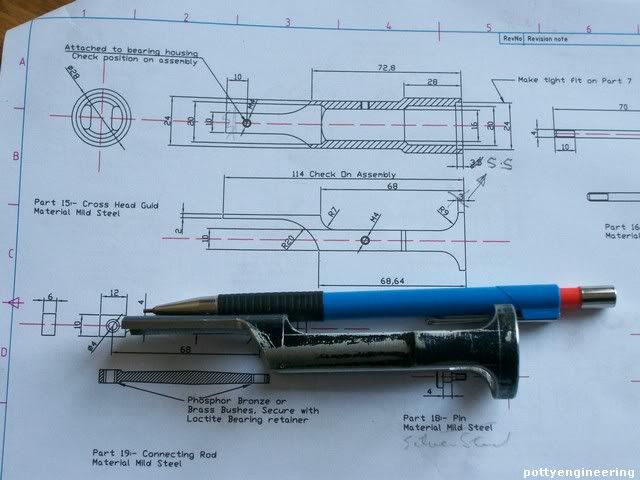
#1-there is no dimension for the boss diameter on the side of the Front Cylinder Cover that faces away from the cylinder.
I made it 10mm
#2--No height is given for the base, although a little trigonometry shows it to be 14mm high.
I deliberatly left it off I was going to add a not to say adjust on assembly to bring cylinder centre line onto crank shaft centre line.
#3--No location is given on the cylinder drawing for the 3mm dia. exhaust port. We know it is centered between the two ends, but not how far offset it is sideways from the cylinder bore.
Its 5mm
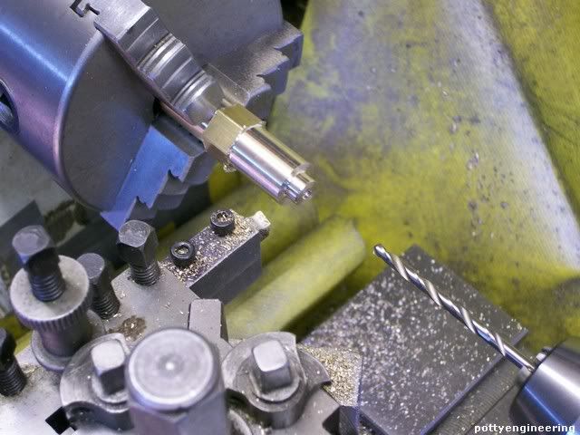
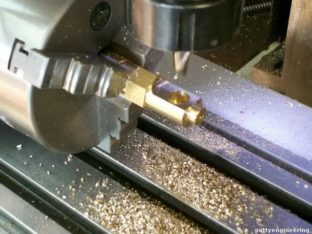
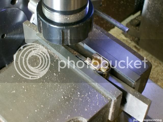
Exta note:- the slot drills I used to cut the port would not cut to the full depth, what I did was chain drill the ports with nearest undersize number drill to 6mm deep, they broke into each other and I mashed them up a bit with a screw driver so that they joined up, then I finished them off with the slot drill. Its only the very lip of the port thats functional, the rest is just air pasage, and the air won't know if its a bit roughed up.
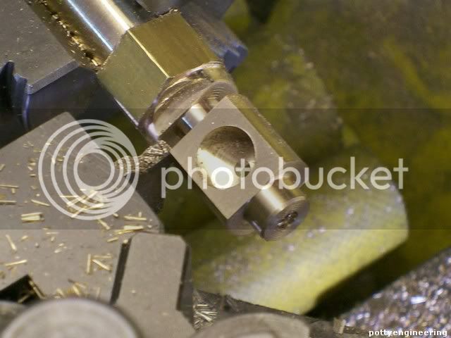
#4--Although it shows the port extending from the 3mm inlet port down into the cylinder bore at the ends of the cylinder, no dimensional information is given on it.
Its 3mm wide by 2mm deep but its not that important it can be filed, I also like to chamfer the edge of this feature so that the piston packing doesn't catch on assembly.
#5-What is the diameter of the recessed area in the center of the piston? These are not criticisms in any way. Its just that someone setting out to build this engine may be a bit confused without that information.
I'm going to use graphite packing so i made it 1.5 deep Ie root dia 12mm, I'm planning on putting a note saying "a suitable O ring may be used" so these feature will have to match the O ring.
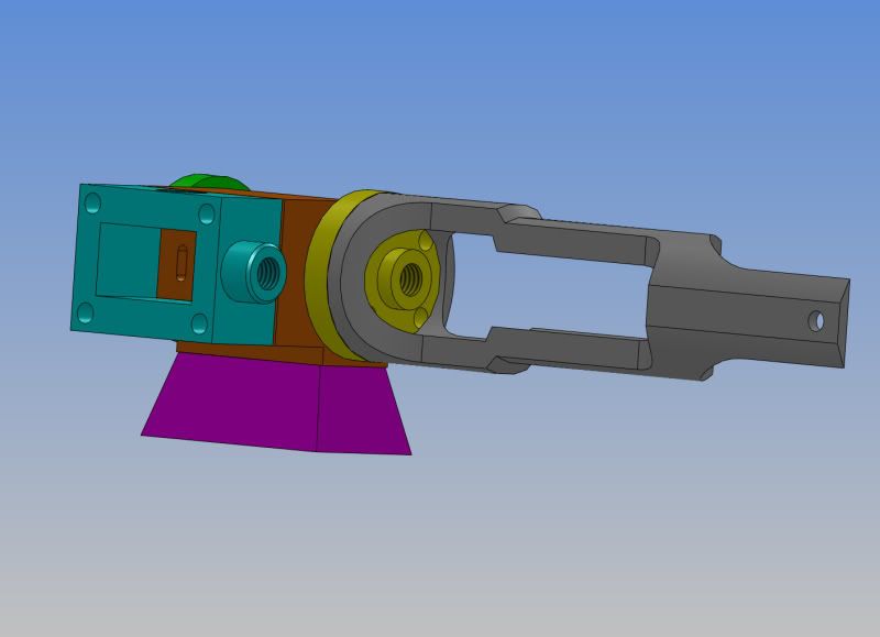
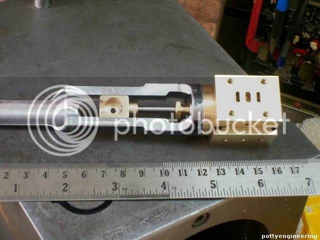
#6 Unless I've done something terribly wrong, there is going to be an interferance between the inside 20mm dia of the crosshead guide and the bolts which hold the cyl. front cover on. Methinks that 24mm dia. x 3.5 deep counterbore in the end of the crosshead will have to be about 5 mm deeper.
I did come across this I simply cut the hole deeper to 5.5mm and widend the web on the outside the same amount. You can see the pencil change here.
Just a few other things I actualy made the bore 1/2" thats what size reamer I had, I've also added an extra tapped hole in the base of the cylinder to screw the base onto its inbetween the two holes already shown and is the same size, likewise I've added the hole to the base countersunk to take a cap screw head.
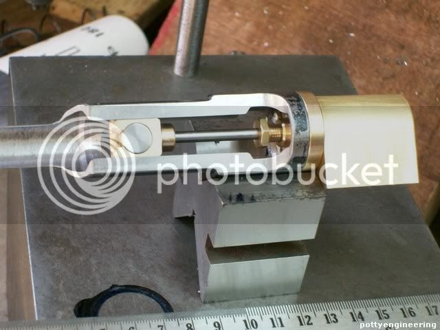
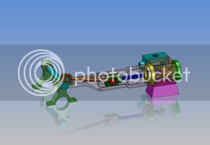
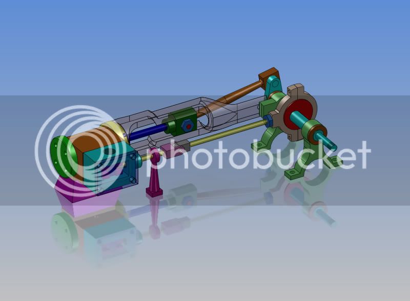
I'm concerned that the cross head guide will foul with the crank web, if it does i will have to put a dog leg bend in the 10mm wide bit of the guide, you 3D model may show this up.
As you may have noticed I do change thing as I go along to suite what kit and material I have, and my whyms.
Thanks for all your interest Chaps
Stew