Vernon, Arnold, Zee...Thank you. You guys keep me motivated.
Bob...glad you're following along.
Dean...The lead shot tip is a good one. I had already milled flats before I read your posts. However, I didn't mill one on the eccentric collar because I figured I'd need flexibility for adjusting timing. I figured I'd just have to live with a burr. The lead shot will eliminate the problem.
Post #44
Plumbing the Boiler
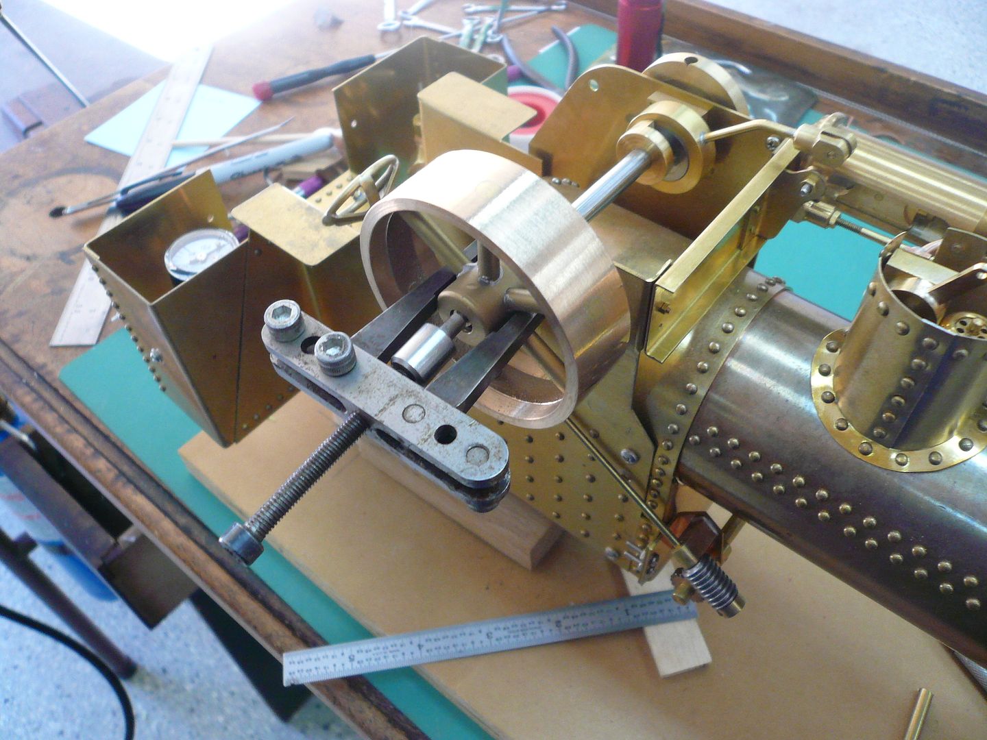
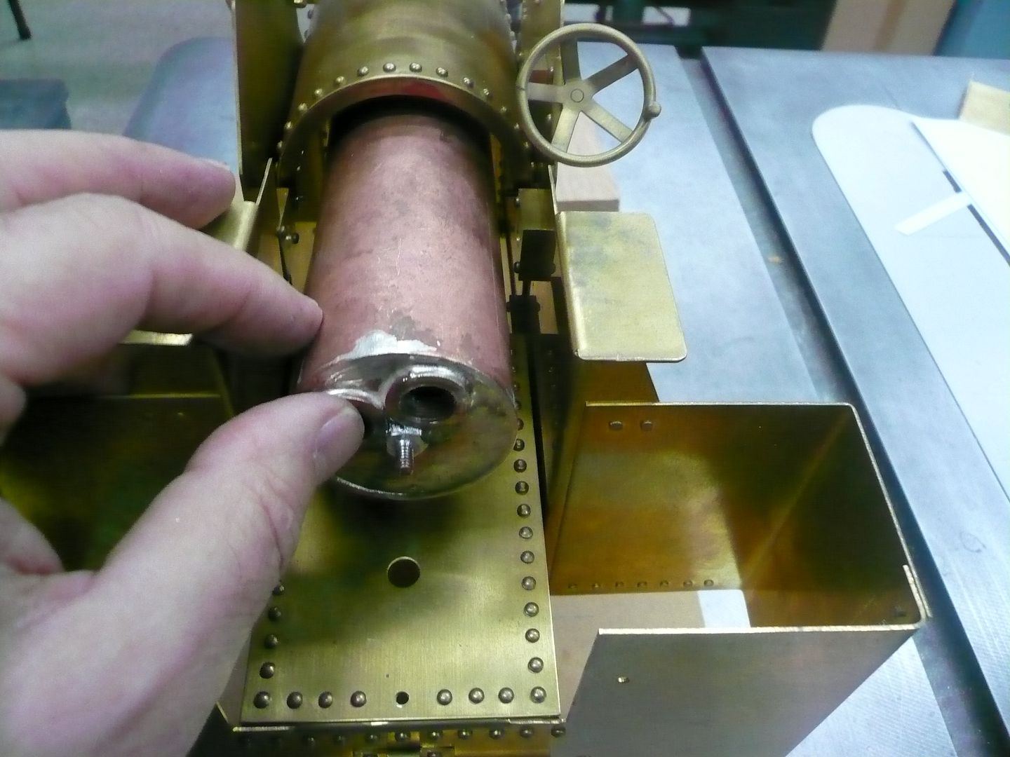
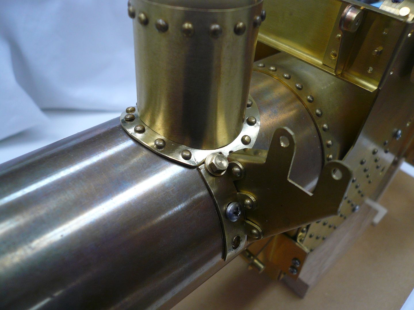
The boiler slips into the boiler housing from the back.
Its held in place in the front by an L bracket screwed to the boiler stay stud and to the boiler housing.
The plans put the boiler housing screw at the very front edge of the boiler housing. That causes the screw to interfere with the smoke box door, so a recess has to be milled in the door (also noted in the plans). All of that can be avoided by moving the hole back 1/2 which I recommend.
There looks like plenty of room around the boiler, so I plan to add a layer of 1/8 insulation before final assembly.
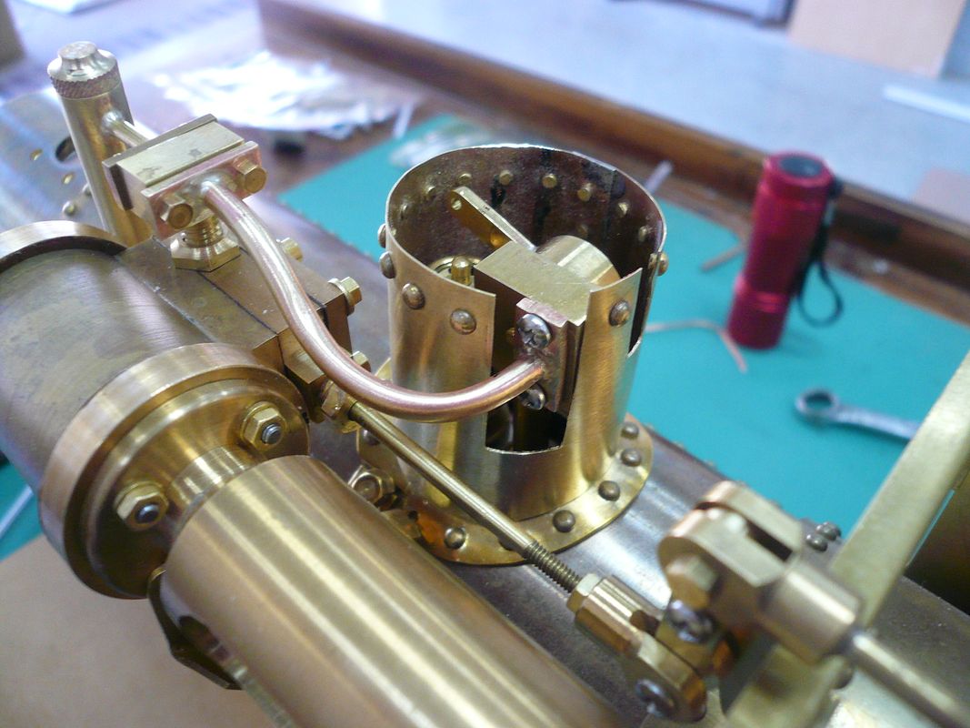
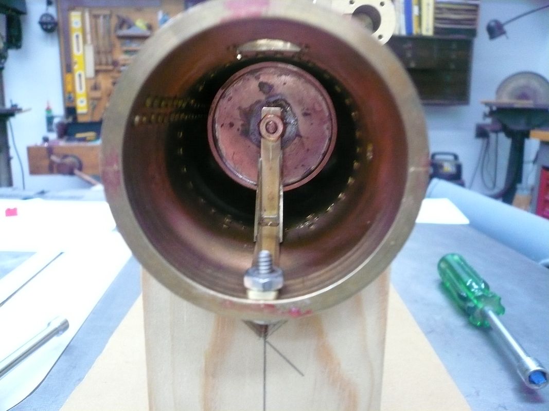
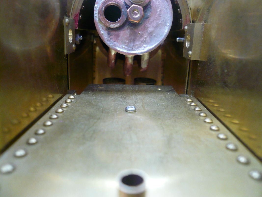
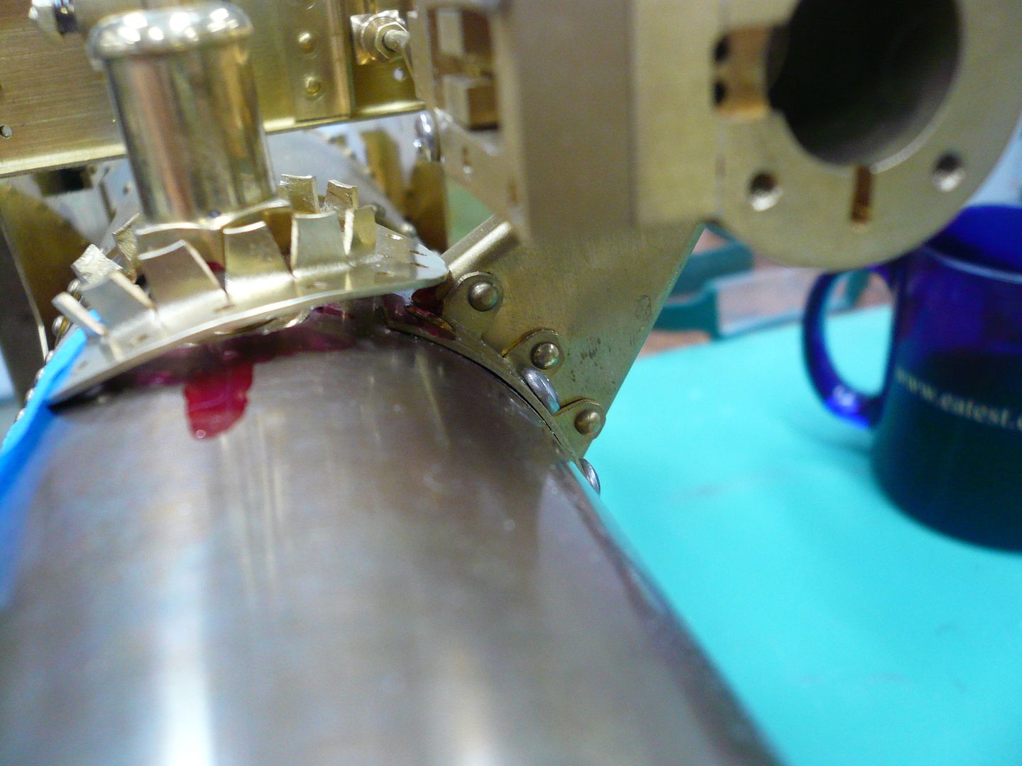
Heres a view from the back showing the relationship between the boiler and the top of the burners.
The rear of the boiler is bolted it to the firebox back sheet by the rear boiler stay stud. Nothing is tightened down in this shot, so final alignment will be better than it looks here.
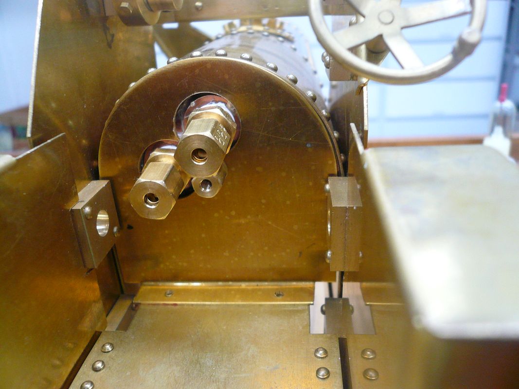
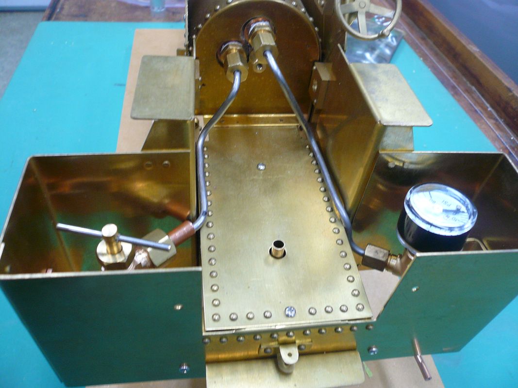
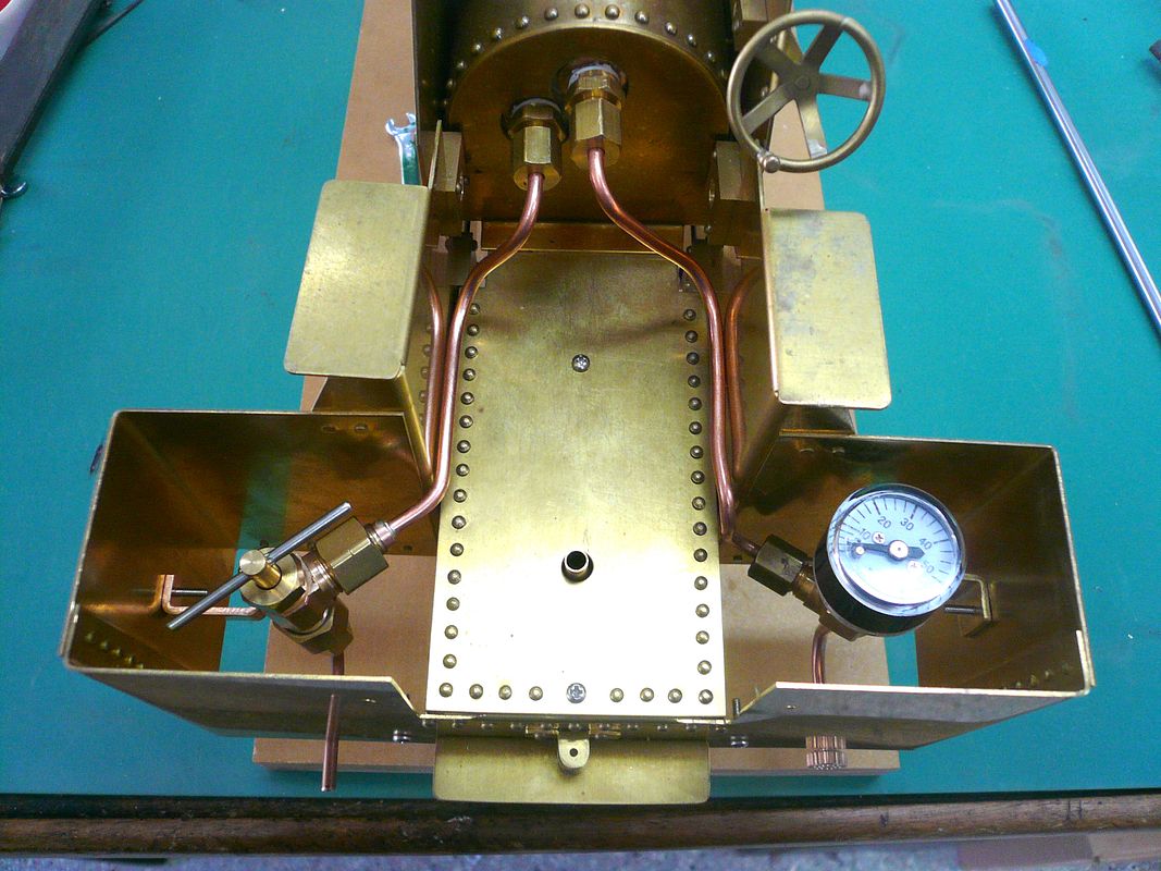
Boiler plumbing uses 1/8 copper tubing and compression fittings. The upper boiler fitting goes to the pressure gauge and the lower to the water inlet/test valve. The center piece that looks like a small fitting is the nut on the boiler stay stud. It had to be made extra long because there isnt enough clearance around the fittings to get a wrench on a standard height nut.
The test valve and the pressure gauge are mounted in the right and left coal bunkers respectively.
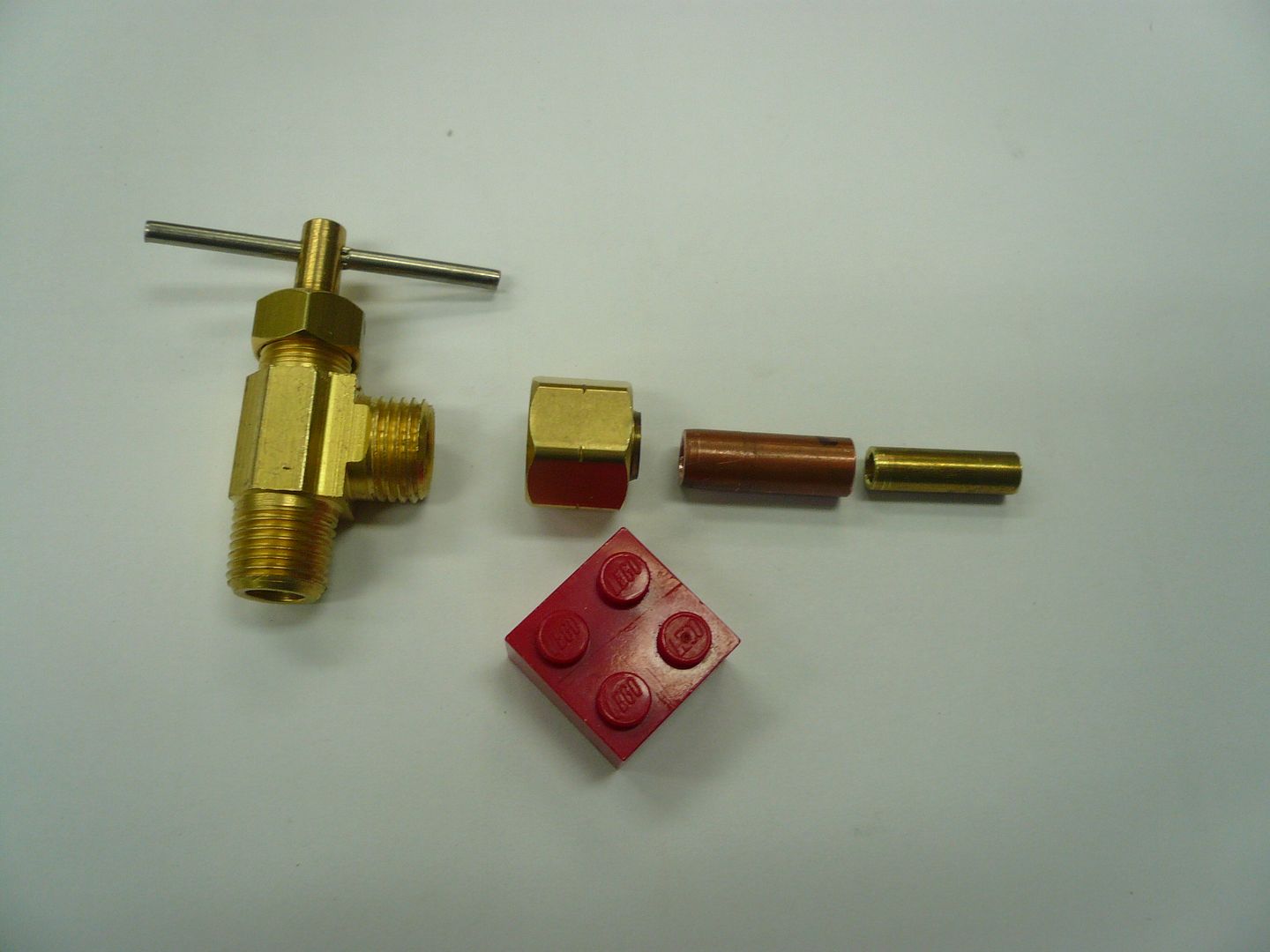
The test valve is a standard humidifier valve available at any hardware store. Its made to use with 1/4 tubing. There isnt room for a reducing coupler on the outlet side so an adapter (two pieces of nesting tubing) has to be made to connect it to 1/8 tubing.
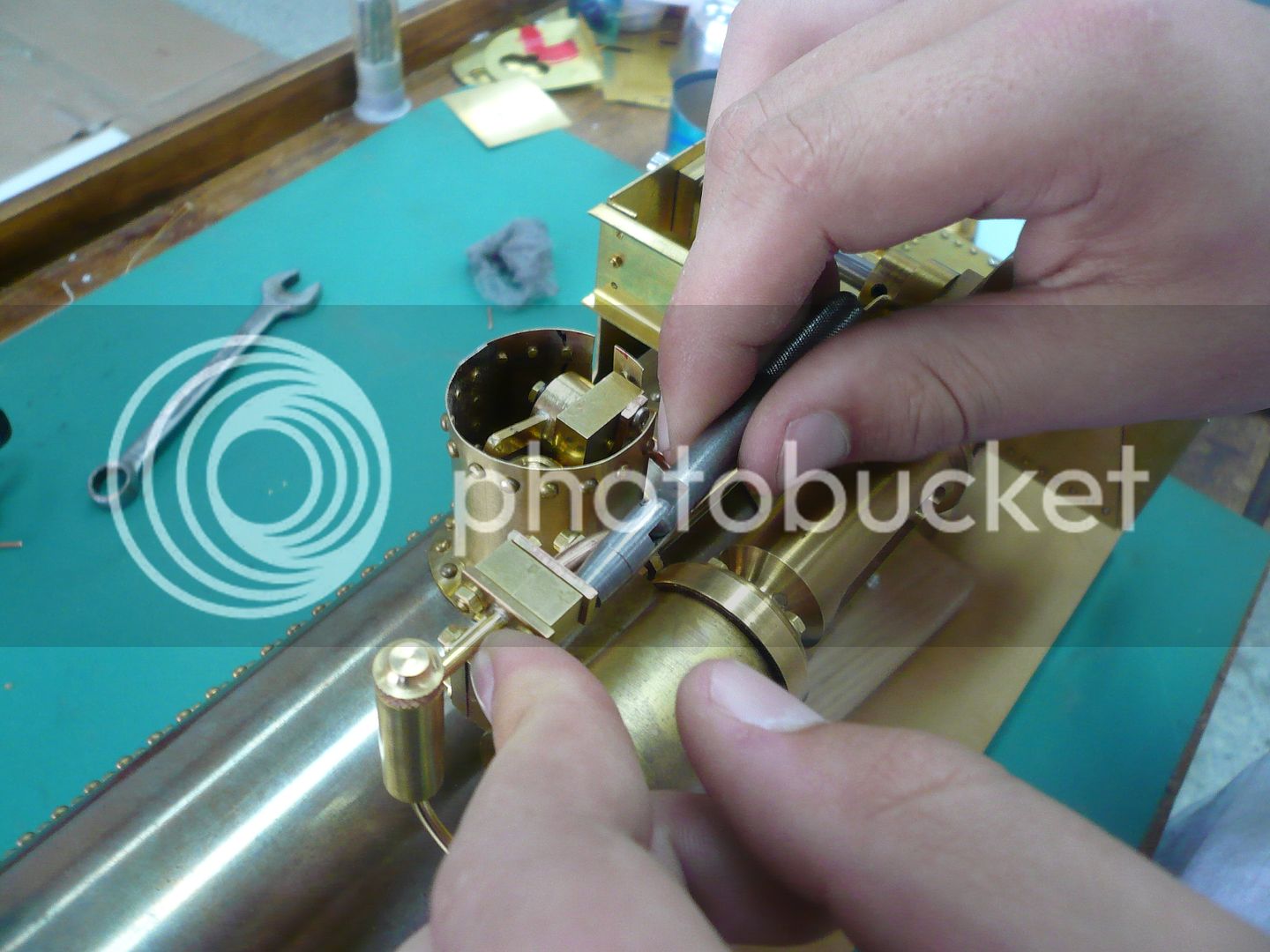
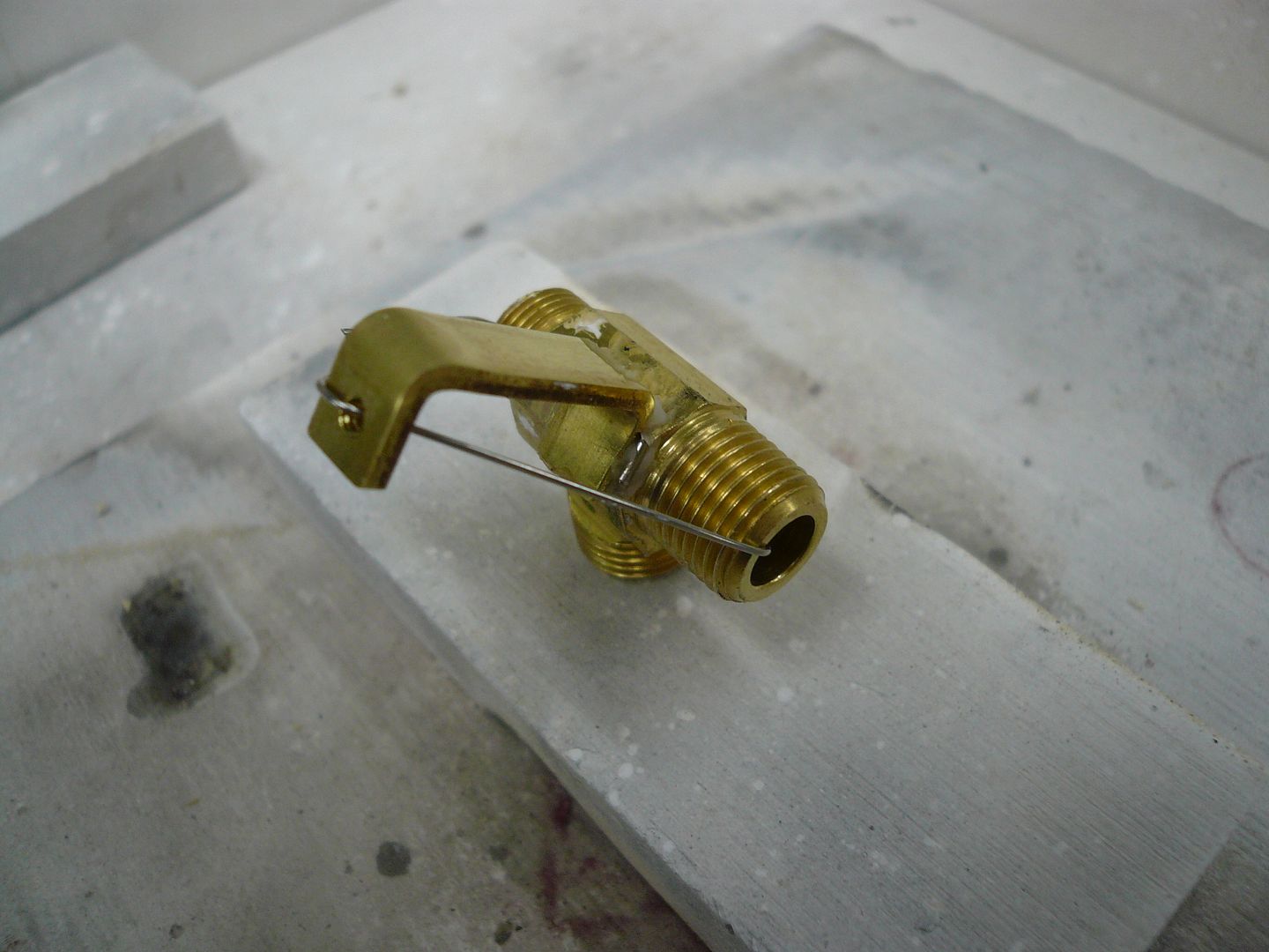
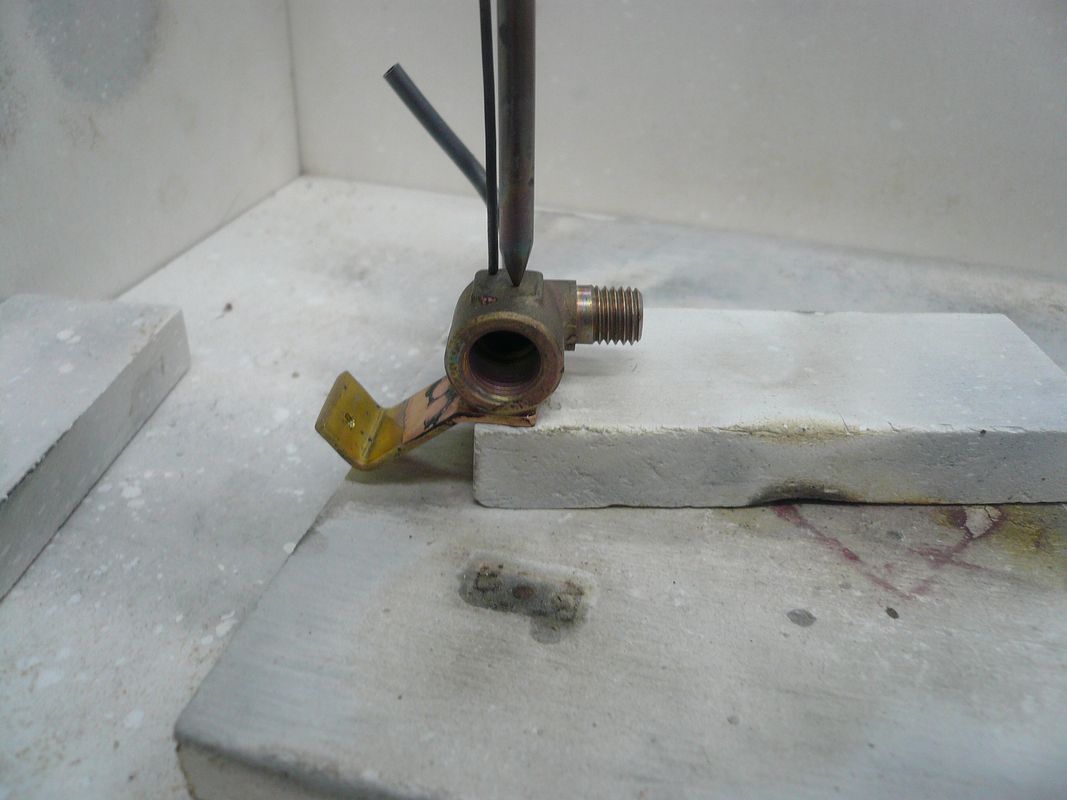
In addition, a mounting bracket has to be made and silver soldered to the valve body. Here's mine wired in place and ready for solder.
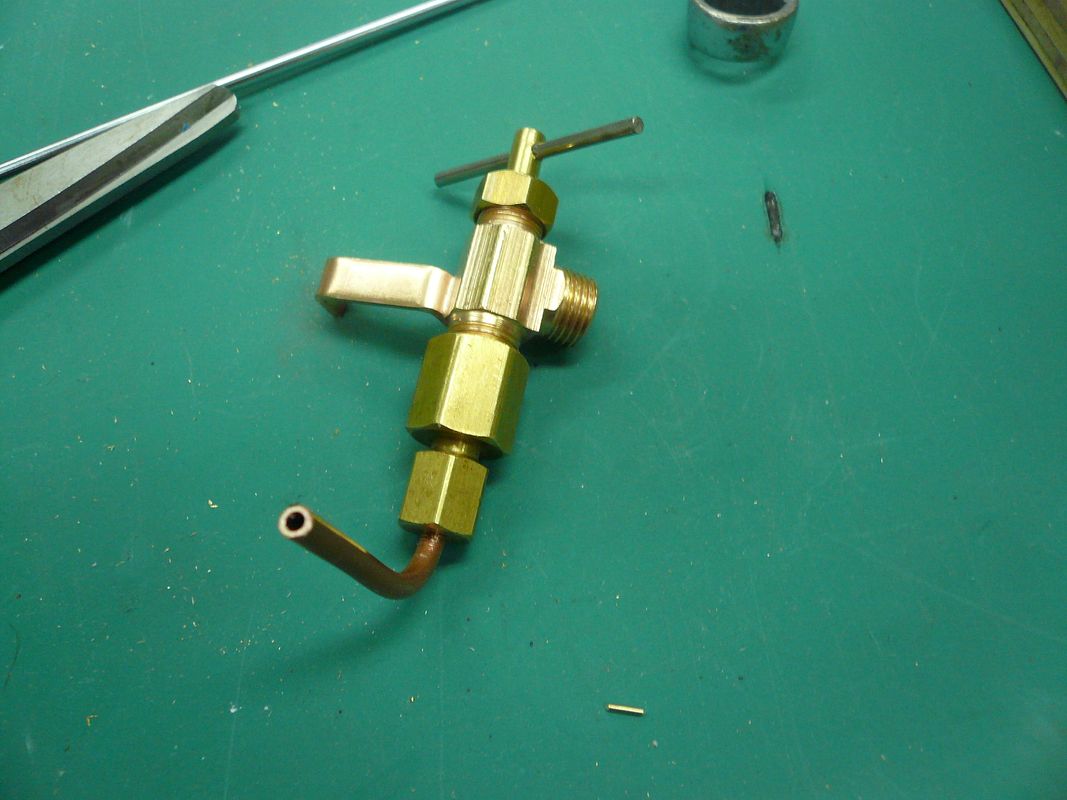
And heres the completed test valve assembly.
The copper tubing extends out the bottom back of the tractor and is used to attach a syringe or pump for filling the boiler.
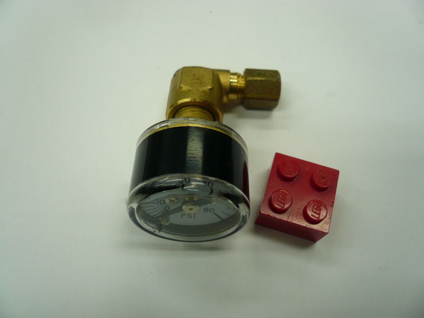
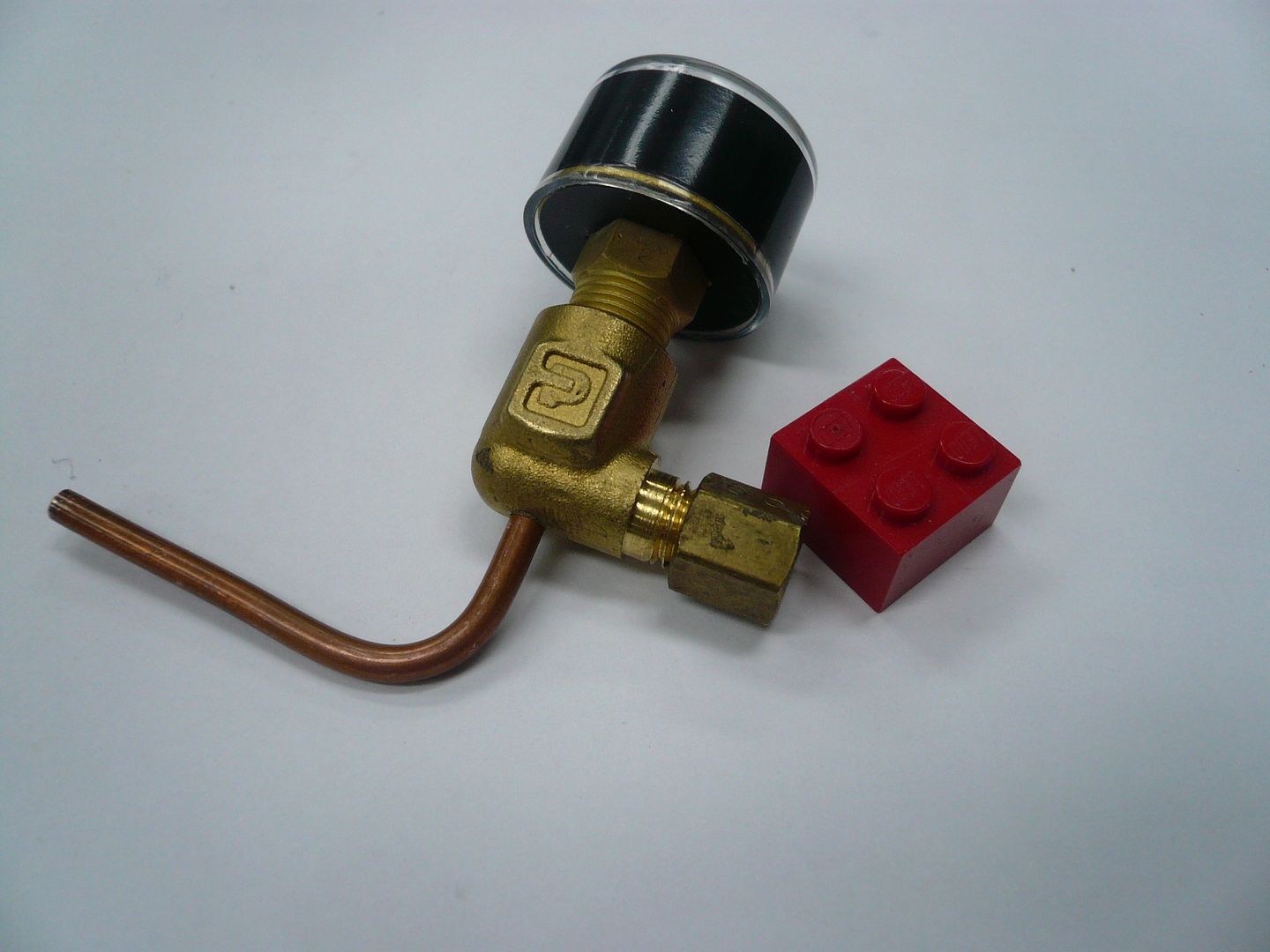
The pressure gauge Im using is a Live Steam Miniature Pressure Gauge that I got from AK Enterprises (
www.livesteamsupplies.com). About $10 as I recall. Its 0-60psi and has a 1dia. face instead of the usual 1 1/2. Theres room for a 1 1/2 dial, but its a tight fit. The elbow is 1/8-NPT to 1/8 compression.
I made one modification to the plumbing that I hope will simplify operation. The tractor is designed to have a pre-measured amount of water pumped into the boiler via the test valve fitting. It seems like thats less than ideal because youre trying to push water into a sealed vessel. Some guys loosen the pressure gauge fitting at the boiler to vent it and then pump water in until it comes out of the pressure gauge fitting. Im taking this a step further and adding a vent valve at the end of the pressure gauge line. It's made by drilling a hole in the elbow and silver soldering in a piece of tubing.
The tubing will have a screw-in plug attached to it and will extend out under the right coal bunker. In operation, Ill remove the plug and pump water in the test valve side until it comes out of this tube, then close the test valve and replace the vent plug. (It should be noted none of this happens with the boiler hot or under pressure!)
The pressure gauge assembly also needs a mounting bracket. It's silver soldered to the side of the elbow. The bracket and the tube were soldered in the same heat.
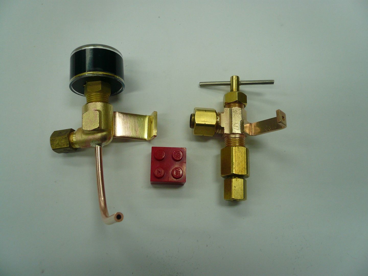
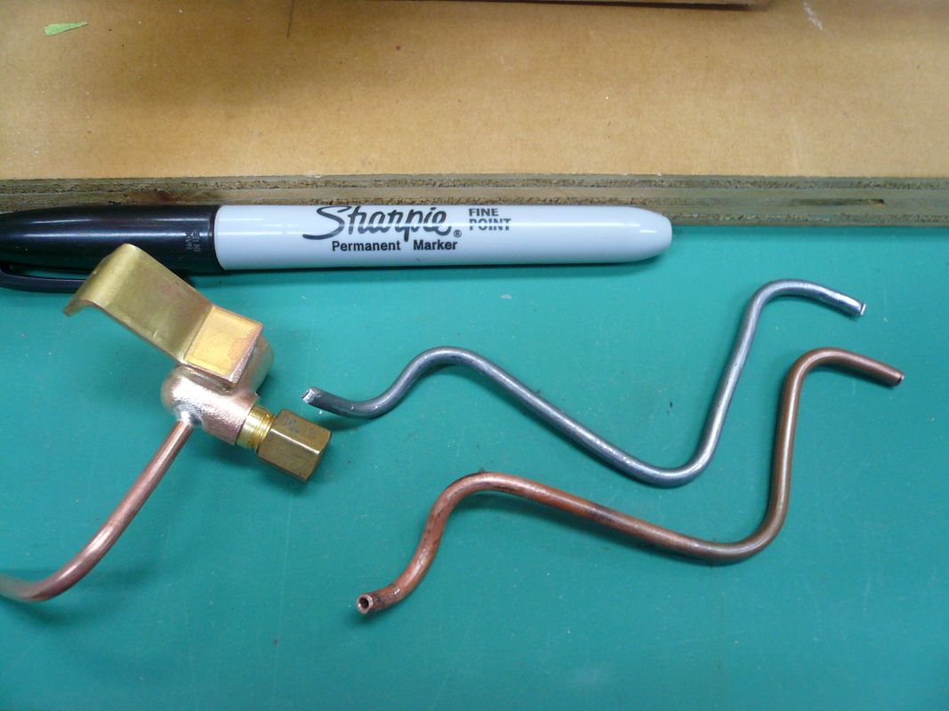
Here are the two finished assemblies less the outlet plug on the pressure gauge assembly.
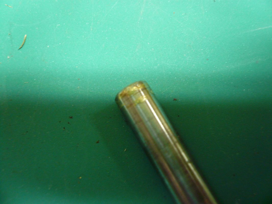
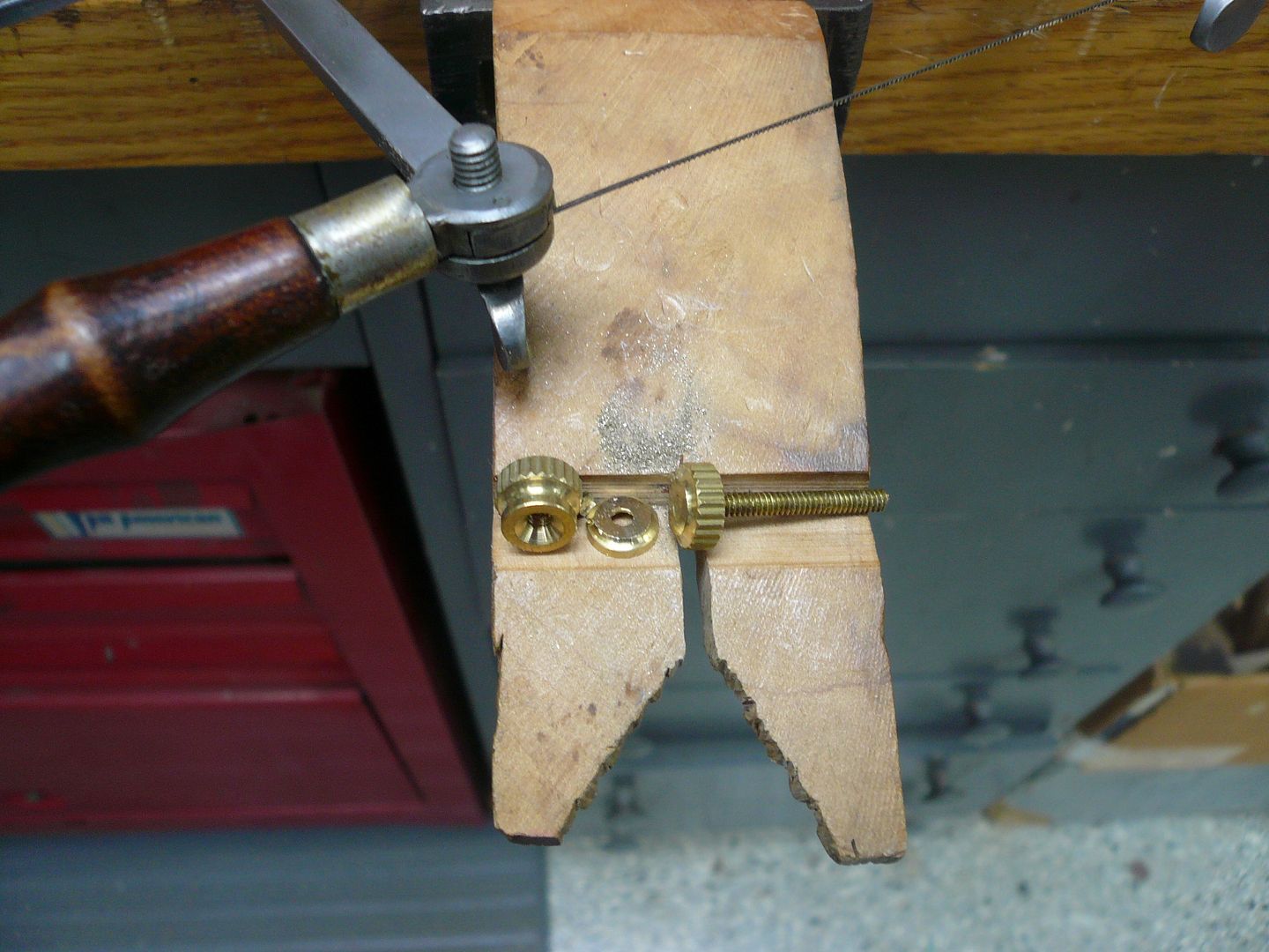
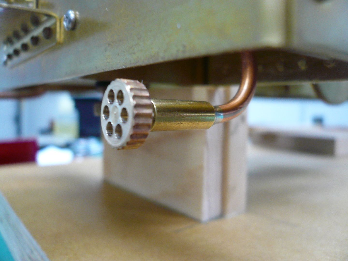
The outlet plug sleeve is a piece of 3/16 brass drilled 1/8" dia. halfway through with the other half tapped 4-40 to accept a threaded plug. The plug is made from an electrical terminal nut with the bottom cut off
and a pointed piece of 4-40 threaded rod. The rod is silver soldered in place, the top is faced in the lathe and six decorative holes added. I used a piece of threaded hex stock in lieu of a rotary table to drill the holes. The point of the plug seats in the end of the piece of copper tube.
The test valve and pressure gauge assemblies were then mounted in the coal bunkers. I used 1/8 soft solder to lay out the pipe locations.
The solder is a lot easier to manipulate than the tubing and its easier to bend the copper against a pattern.
I used the groove in a round piece of stock method to bend the tubes, but the first thing Im going to do once this tractor is finished is make one of George Britnells tubing benders.
Heres a view showing everything snugged up and in place.
Ill need to add some wooden dowel sleeves to the handle of the test fitting to avoid burnt fingers.
Regards,
Dennis


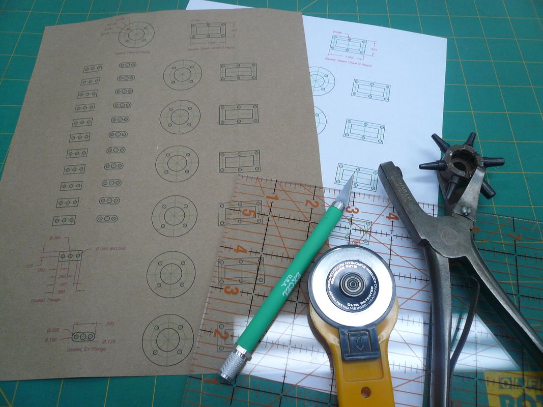
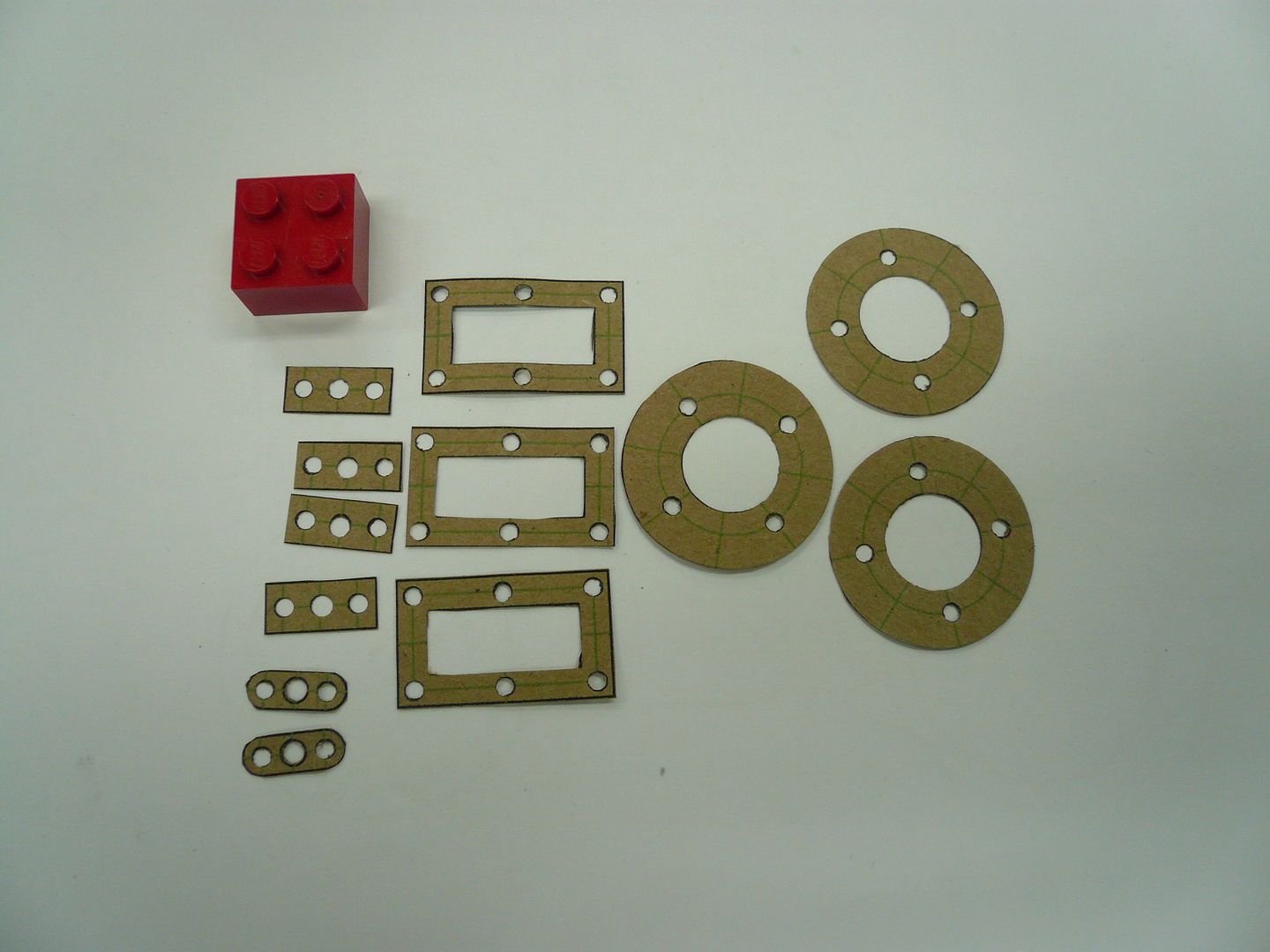
") ). This required gaskets. I used a piece of kraft paper shopping bag (Thank you, Doug Lanum) run through my printer to make mine. Here are my tools of choice.
). This required gaskets. I used a piece of kraft paper shopping bag (Thank you, Doug Lanum) run through my printer to make mine. Here are my tools of choice.