Building Rudy's Steam Tractor

Home Model Engine Machinist Forum

Help Support Home Model Engine Machinist Forum:

This site may earn a commission from merchant affiliate links, including eBay, Amazon, and others.
Excellent work Dennis :bow:

Kind regards, Arnold
 
Jeff, Jack & Arnold...Thank you.

there HAS to be a way to incorporate engine reversing and a clutch mechanism to those dummy levers
Jim,
I'm with you. It's a shame to have those levers there not doing anything.

Post #47

Throttle Linkage

The throttle lever and throttle are connected by a 1/16” rod. The plans are silent about how the ends are attached, but from the photos it looks like Rudy used “L” bends on his. I’m going to use a light clevis on each end.

I made the clevises by starting with a piece of 1/8” x 3/16” 0.014” wall tubing and then drilling 1/16” holes for a clevis pin and the throttle rod.
P1060953.jpg


After drilling the pieces are cut off 3/16” long.
P1060954.jpg


The hole for the throttle rod wasn’t actually necessary, but it helped locate the piece for soldering.
P1060957_edited-1.jpg


I used silver solder paste and a third hand for holding. Note the top end is already soldered on.

After soldering, the end of the rectangular tube was ground off and rounded to form the clevis.

The clevis pins are made from 1/16” rivets drilled #60 (0.040”) for a cotter pin.
P1060977.jpg


P1060985.jpg


The cotter pins are made using 0.020” copper wire formed around a piece of 0.041” wire.
P1060989.jpg


They didn’t all turn out. Here’s a shot of some good, bad, and ugly ones.
P1060997.jpg


I also discovered that it’s tough to get two 0.020 wires through a 0.040 hole, so I ended up flattening one side of the wire by drawing it under a file held on a hardened steel plate and then forming the pin. Same as real cotter pins.

Anyway, here’s the rod in place.
P1070221.jpg


For now, the pins are just held with a piece of wire. Now that I look at this picture, I can see that the heads of the pins are way out of scale. I’ll have to grind them smaller. That’s one I’ll add to the list of things to do later while I’m waiting for the paint to dry.

That’s it for today. Sorry about the short post, but not much shop time this week.

Dennis


It's great, Dennis. Thanks for showing how you made the cotters.
What a sweet machine it's becoming.

Dean
 
Very neat idea on how you made the clevis's Dennis.

And to say the least, its looking really fine.

JimN
 
Dean, Jim, Speedy...Thanks for watching.

Post #48

Dummy Pressure Gauge

Rudy’s model has a purely decorative dummy pressure gauge mounted on the steam dome. It’s made from 7/16” diameter brass and mounted on a 3/32” standard.

I turned the OD first and then cut a 3/8” diameter recess to represent the dial.
P1070022.jpg


Then cross drilled it 3/32” for the standard,
P1070034.jpg


parted it off and silver soldered in the standard which is a piece of 3/32” rod drilled and tapped 0-80.
P1070048.jpg


Rudy stopped at this point, but I thought I’d kick it up a notch using this photo.
222159377_o.jpg


I cleaned it up a bit in Photoshop to get this.
222159377_ocopy.jpg


The Photoshopped picture was then printed so the dial face diameter, as printed, was 3/8”.
P1070052.jpg


The dial was then cut out using a punch made from a piece of 3/8” ID steel tube. I printed multiple copies of the dial because I assumed (correctly) that it would be tough to get the punch exactly centered.

I had left a slight burr when I cut the recess for the dial, so I just popped the dial in and it seems to be secure.

P1070240.jpg


If anyone wants a higher resolution copy of the dial jpeg, PM me and I’ll send you one.

Happy Easter everyone!

Regards,
Dennis
 
Beautifully done Dennis. And here I thought sure you would have put a stop valve plumbed over to a faux governor at the steam chest in that spot. :big: That is one of THE nicest TEs I have seen in a long while.

BC1
Jim
 
That looks perfect, Dennis!
You have such a great eye for detail.

Dean
 
Beautiful work, Dennis. Thm: Thm:
All the detail work you do really sets it off.
Gail in NM
 
I love the gauge, actually I am impressed with everything, the rivets look great also. well done. Tad
 
Really nice job you're doing here Dennis. This is going to be a lovely steam tractor when finished.

Chuck
 
Great work Dennis - your attention to detail is amazing!

Kind regards, Arnold
 
WOW!!!! Dennis.

Your work is just beautiful. I especially like the detail on the levers and then to top it off with the gage.

You are at the top of your class in model building.
 
Dean, Zee, Gail, Bernd, Chuck, Arnold & putputman...Thank you for your kind comments.

Thayer...I'm going to you for future Photoshop work.

Jim,
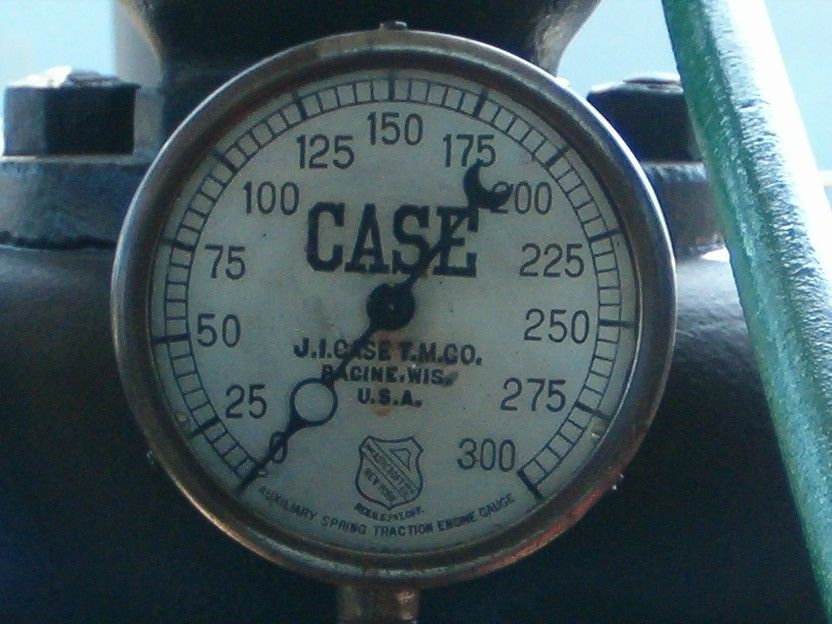
A "stop valve plumbed over to faux governor" crossed my mind, but this is a representational model AND I'd like to finish it in my lifetime! :D

Post 49

Steering

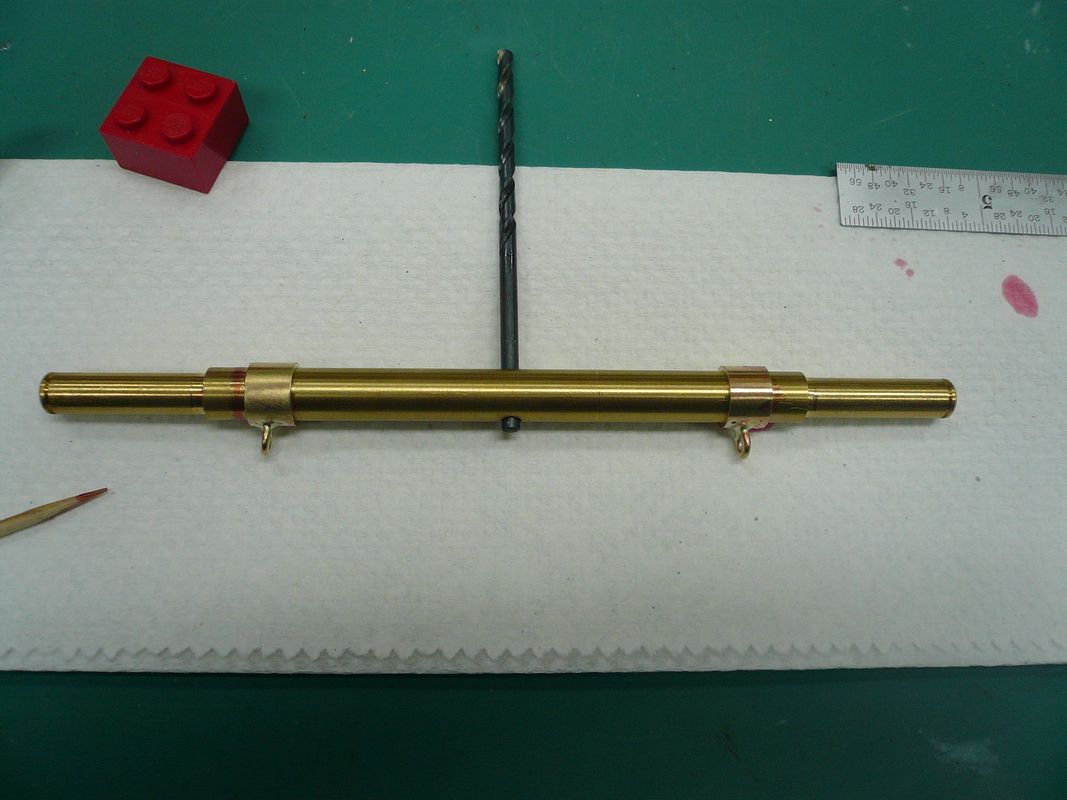
I made the front axle much earlier in this build, but hadn’t provided for a way to attach the steering chains.
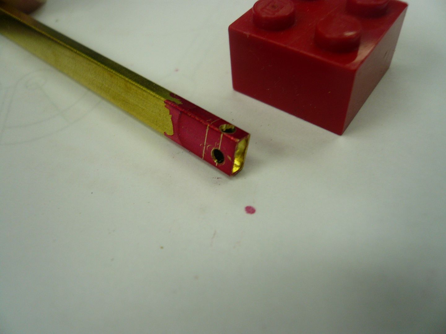
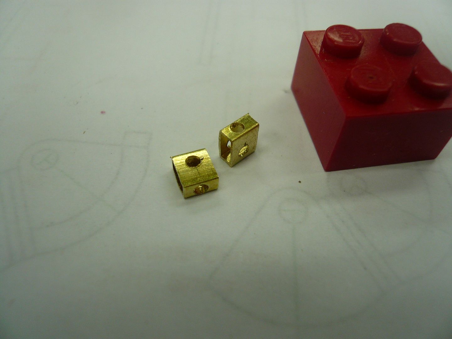
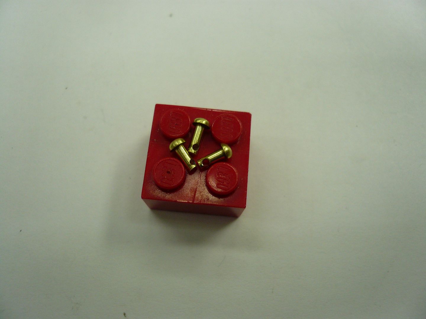
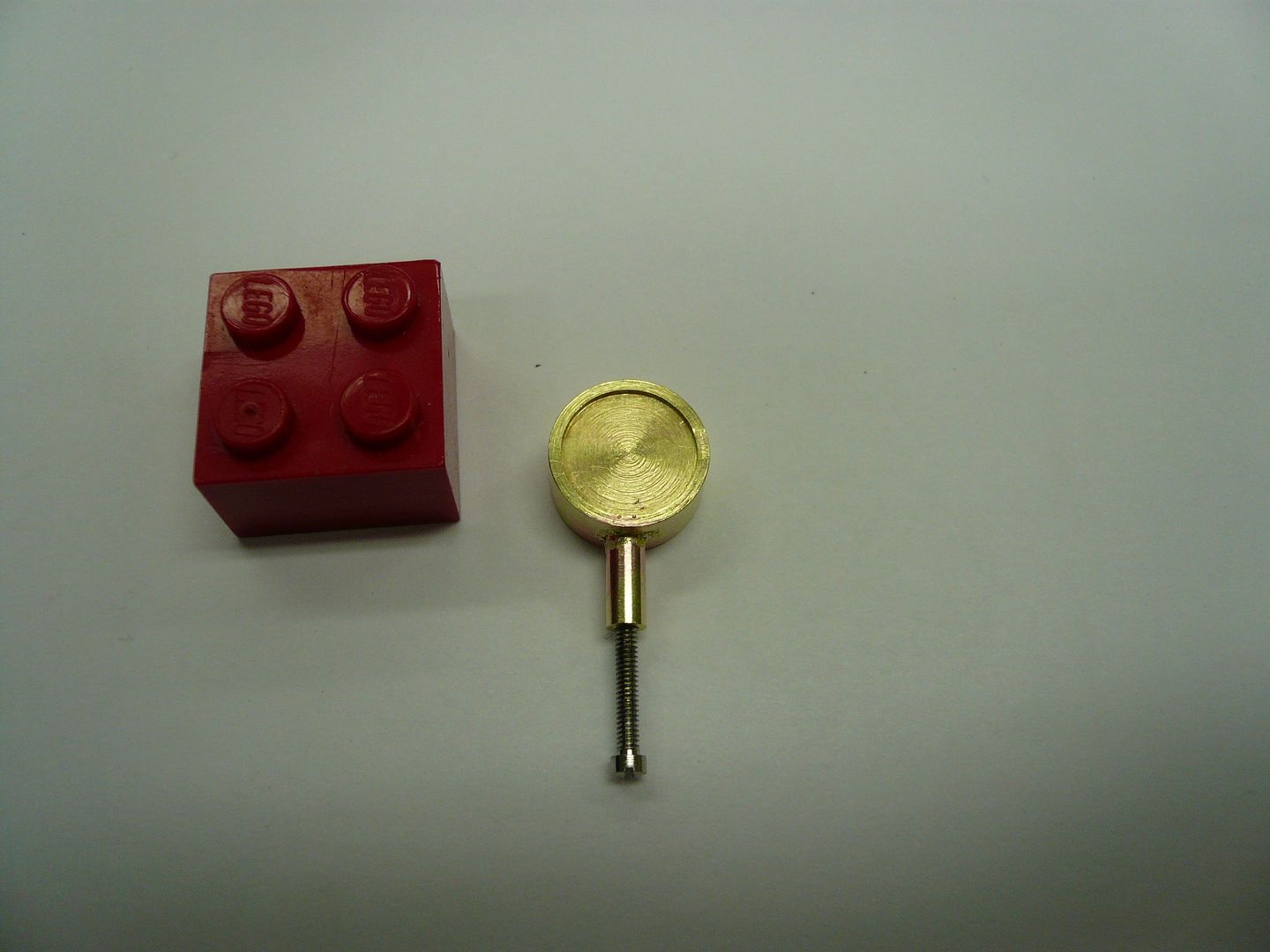
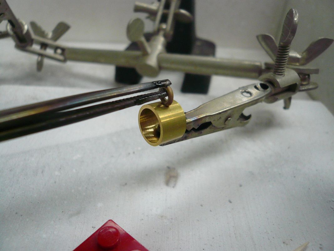
The first step is to cut two 1/4” long pieces of 3/8” tubing (5/16” ID) to use as attaching collars. These slip over the axle. Next bend two small rings to serve as chain attachment points and silver solder the rings to the collars.
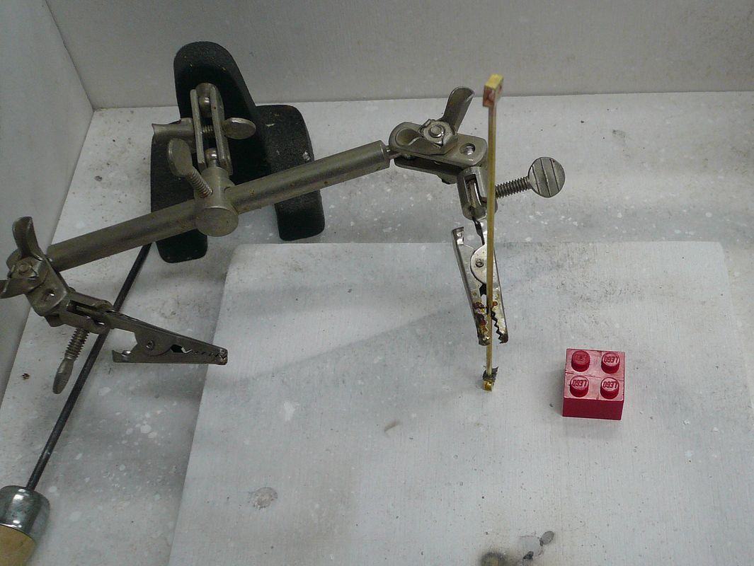
P1060966.jpg


It took two “Third Hand” devices to hold things in place.

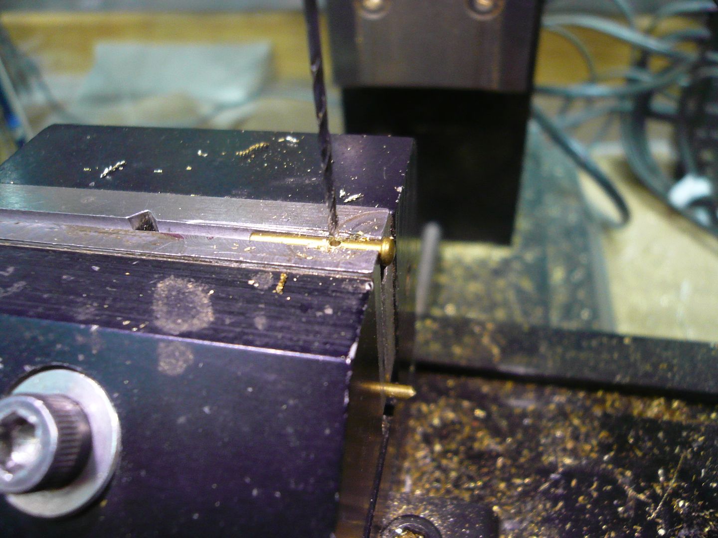
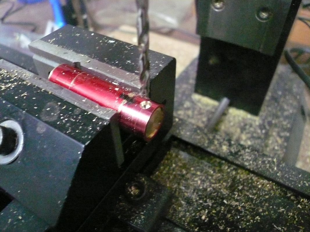
Then position the collars on the axle and Locktite them in place.
P1070245.jpg


The drill bit helps get the orientation right. As you probably know, any Loctite not in the joint wipes off cleanly after the joint cures.

Finding steering chain I was happy with was a real ordeal. I don’t know how many samples I bought from various craft, beading and jewelry supply stores. They were all either; too shiny, too small, too large or too weak. About the time I was ready to compromise, I noticed that Gary Hart (ghart) had what looked like exactly the right chain on his tractor. I PM’ed him and he said he used clock weight chain. Bingo! Don’t know why I didn’t think of that.

So, off to the nearest clock repair store. I told the guy what I was looking for and he brought out his junk drawer and let me dig through it. I found exactly what I needed. He said if I wanted more to ask for “No. 1 Cuckoo Clock Chain”. Link dimensions are 0.145” wide, 0.290” long and it’s made from 0.033” wire. Six feet for $3 bucks, plus he let me take whatever I wanted from the junk drawer. He was an older gentleman and said mechanical clock repair is a dying business and he would never use up the pieces. Depressing.

In Gary’s email he also pointed out that he had added a guide “spring” to the steering chain roller to keep the chain from tangling. It’s a nifty enhancement. Thanks, Gary.

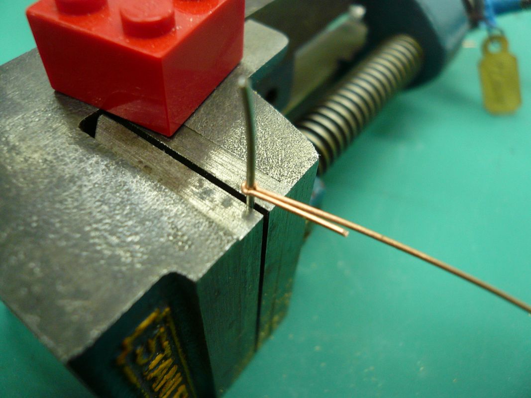
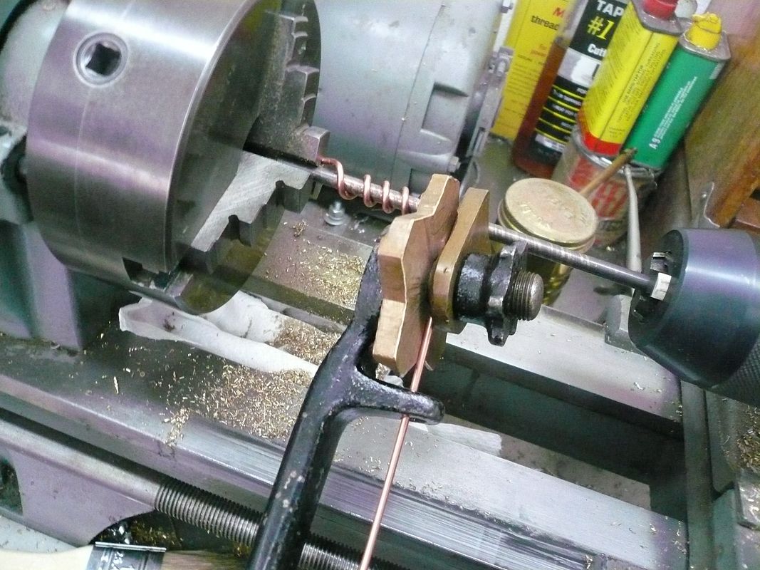
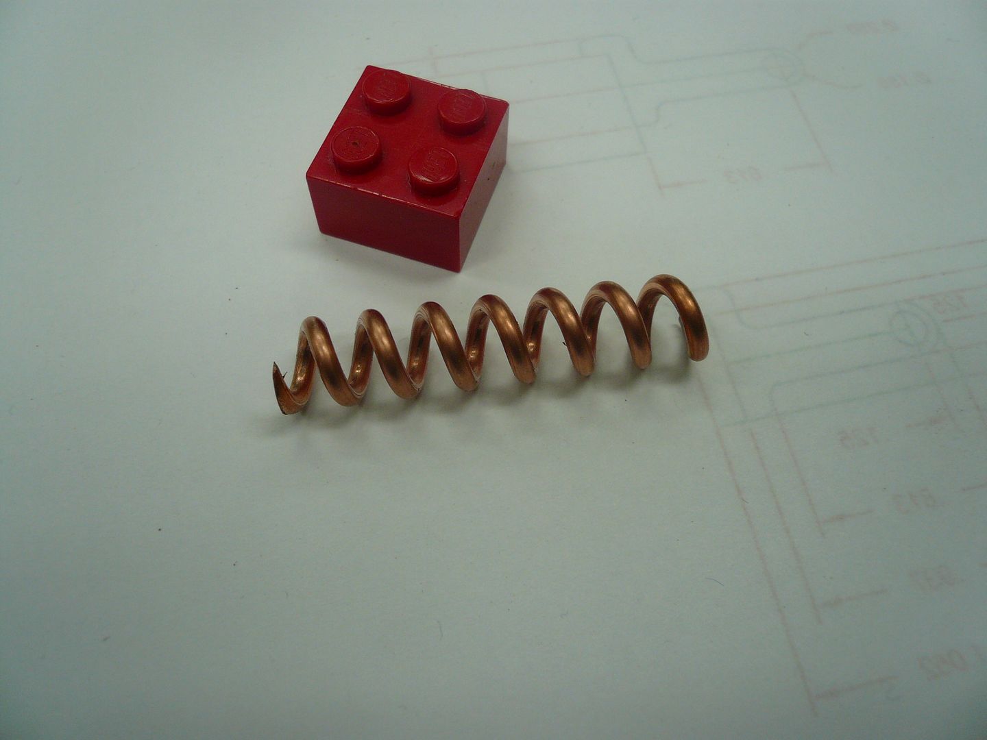
I made my guide out of a piece of 12AWG copper wire. Probably should have been brass, but I didn’t have any.
P1070243.jpg


(Note: The spring shown is a right hand one. To steer properly it needs to be left hand. All of the following photos except the last one show right hand springs. Sorry, but by the time I figured this out and how to wind a left hand one, I was too frustrated to retake the photos.)
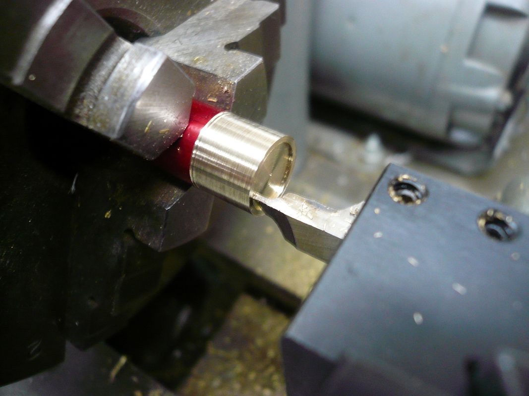
The spring is wound around a 3/16” mandrel. I turned the lathe by hand…no power (although it could be powered if you know what you’re doing).
P1070248.jpg


The tool I’m using is a “Hojarth Perfection Spring Winder” patented in 1907. I’ve had this for years (I collect old tools) and never had occasion to use it before. It seems to work very well.

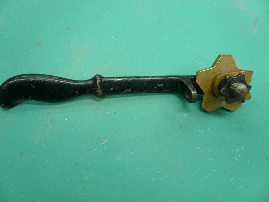
The tool consists of a handle, a tension adjusting nut, clamp (brass) and a spacing guide (brass). The spacing guide has various thickness lands and it controls the spacing between turns. I picked a land that matched the link width on my chain.

In use, the wire is threaded through guide holes in the handle and between the two brass plates. Feed enough wire through to hook on the chuck and turn the chuck to wind the spring. The amount of tension you put on the star nut determines how tight the spring gets.

Here’s an overall shot of the winder.
P1070374.jpg


This one is about 9” long. They came in several sizes. If you’d like to know more, Google patent 861,283.

To wind a spring without a Hojarth, check out Deanofid’s excellent thread, “Springs and Things" here

But I digress…

It took me numerous tries to figure out that I needed a left hand spring and that turning the lathe backwards doesn’t get you one. To get a left hand one, you have to wind from the tailstock chuck toward the headstock. If there’s another way, please tell me. At this point, I get a headache just thinking about it.

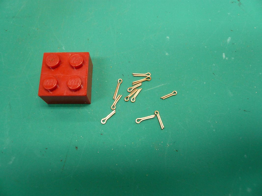
Anyway, after winding the spring/guide, grind the ends perpendicular to the axis.
P1070242.jpg


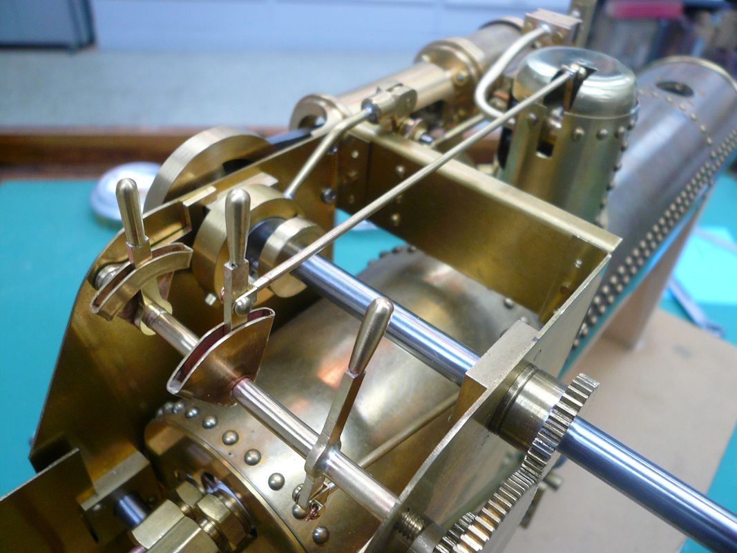
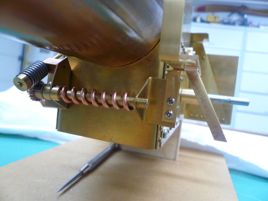
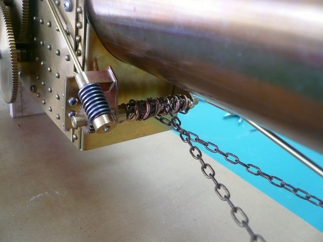
and install it on the steering chain roller and wind on the chain.
P1070251.jpg


This is the first photo with a correctly wound guide. Also note that the chains cross. The guide and the crossed chains are similar to the real Case tractor.

Regards,
Dennis


As always Dennis, really nice looking work.

JimN
 
Another great write up and nice clear pics from you, Dennis. I'm starting to sound like a parrot;
"looking good, looking good", but, you know... Looking good!

That's a neat old winder. I wouldn't have known what it was at first sight, but would have bought it, just because of the shapely handle.

Dean
 
Deanofid said:
That's a neat old winder. I wouldn't have known what it was at first sight
Dean

Me neither. :eek:

Great work Dennis :bow:

Best Regards
Bob
 

Latest posts

Back
Top