Building Rudy's Steam Tractor

Home Model Engine Machinist Forum

Help Support Home Model Engine Machinist Forum:

This site may earn a commission from merchant affiliate links, including eBay, Amazon, and others.
Post #45

Ladder

The ladder is purely decorative and is made from 3/16” brass pieces silver soldered and riveted together. There’s really not much machining. The tricky part is holding the parts for soldering. I silver soldered mine, but soft solder would work equally well.

I positioned the steps at the correct angle and used a machinist vise to hold them in place while I tied on binding wire. The binding wire needs to be pulled pretty tight.
P1070001.jpg


With the binding wired on, the part can be moved to the soldering hearth where it’s held in a third hand. The third hand lets you position the ladder for good access for soldering. I positioned mine so the solder bits would be on the underside of the finished ladder.
P1070004.jpg


Here’s the completed ladder sub-assembly.
P1070007.jpg


The ladder is soldered at 60 degrees to the running board. I found the easiest way to hold it in position was to use binding wire and form a tripod.
P1070013.jpg


P1070015.jpg


The ladder assembly also has two brackets that are riveted to the running board and bolt to the engine. They’re made from .032” brass and fabricated using paper patterns glued to the brass.
P1070017.jpg


Here’s the completed ladder assembly with the brackets riveted in place.
P1070038.jpg


The notch on the upright is to clear a rivet on the cylinder mounting bracket. Smaller rivets or countersunk rivets might be in order. If these were scaled up to full size they’d be a definite tripping hazard. :D

And here’s the ladder mounted on the tractor.
P1070046-1.jpg


The mounting hole on the cylinder bracket is not shown on the plans. It was tricky to drill with the cylinder in place so you may want to make the ladder earlier in your build so the hole can be located and drilled with the bracket off.

Sorry about the short post, but I’m at the stage where what’s left is a lot of fiddly fitting and fabricating. Lots of time consumed, not much to show.

As of this week, I’ve been working on this project for one year. I’m ready to be finished, but still have a lot of little bits and pieces, not to mention painting, to go. I’m hoping the 80/20 rule doesn’t apply here (80% of the effort in the last 20% of the project).

On the bright side, I’ve learned a lot over the year, both from you guys and from experience.

Has anyone else taken over a year to build this tractor?

Regards,
Dennis
 
4156df said:
Post #45

On the bright side, I’ve learned a lot over the year, both from you guys and from experience.

Has anyone else taken over a year to build this tractor?

Regards,
Dennis

Dennis,

I have been in awe of your workmanship and progress. I am also in the process of building Rudy's tractor and have been working on it for almost 18 months. I am currently working on the wooden roof and after that will tackle the steps, and last few fiddly parts. If it wasn't for your posts, I do not think I would have ever finished the steering mechanism or some of the other parts. Thank you for sharing your work and your thoughts.

Harold

 
Beautiful work. I know I've said it before. Can't add much more. Just beautiful work.
Worth how ever much time is spent on it when it comes out looking so good.
 
I am sure you are just sick and tired of hearing this ;) but your work is just wow! The difference between this and the stuff that I am turning out (I'm just learning) is sort of the difference between Mt Rushmore and a small piece of gravel!!!

I have a process question for you if you do not mind. The shot of the ladder after soldering is all blah looking with discoloration and solder/flux yuk everywhere and then the next shot it appears to be a piece of gleaming jewelry. I would not mind to find out a little about your clean-up/polishing process if you would be so kind.
 
Sweet, another Lego guy!

Rudy's Tractor is on my to-do list and you're making a really nice one for lots of inspiration.
 
Cheer up guys,
Mine has been on the back burner since 1975. That was when Rudy first published is plans in Poplar Mechanics

Maybe one day

The time spent building is just as important as finishing
 
Dennis, :bow: :bow: ;D

A year seems to me to be a short time for your progress; from the little experience I have I know how much time it takes to try and get each little part as well-finished off as you make yours. As to the 80/20 rule... It seems that that is unfortunately true ;), but it will be oh-so-worthwhile in the end!

Kind regards, Arnold
 
Doug, Harold, Zee & georgeseal...You guys have made me feel a whole lot better. Always nice to have company. :D

I have a process question for you if you do not mind. The shot of the ladder after soldering is all blah looking with discoloration and solder/flux yuk everywhere and then the next shot it appears to be a piece of gleaming jewelry. I would not mind to find out a little about your clean-up/polishing process if you would be so kind.

compressor man
The only thing done to the ladder from the after solder shot to the following one is about a half hour in citric acid pickle and then a good brushing with a brass bristle brush dipped in water and dish washing detergent. This is the brush I use.
P1070214.jpg


It's a fine bristle and is available on line from jewelry supply houses.

HOWEVER, the ladder is not a representative example of my parts after pickle. Because I wasn't sure if I was going to paint it or not and I knew I wouldn't be able to get to the parts after they were soldered together, I sanded them to the final stage before soldering. All edges were sanded smooth using wet-or-dry paper lying flat on my table saw. I use it dry and went from 320 to 400 and finished with 600.

Normally I wouldn't finish a part this early. If you look closely at the pictures, you can see little nicks and dings from the binding wire and riveting. These will all have to be taken out somehow before painting.

If you search this board for "bling" and "polishing" you can find all kinds of good info from guys who really know what they're doing. Bogstandard's posts were particularly helpful to me.

Dennis
 
If you search this board for "bling" and "polishing" you can find all kinds of good info from guys who really know what they're doing. Bogstandard's posts were particularly helpful to me.

Dennis

From guys who really know what they are doing?! I believe that you are in that lofty group yourself you humble fellow. ;)

Thanks for the reply. Citric acid pickle...is the stuff found in the canning section of the grocery store?
 
Yep, the stuff you get in the canning department, although I get mine online at Bulk Foods. They've got the best prices I've found.

There's a good thread on pickle here.

Dennis
 
Control Levers

Real engines had three motion control levers: reverse, throttle and clutch. This model only has a throttle. However, I’m adding dummy levers to represent reverse and clutch.

They mount on a 1/8” shaft that runs between the horn plates. The levers are made from 1/16” brass.
P1060879.jpg


The upper hole is for a 1/16”D control rod. At this stage I drilled both holes 1/16” so I could use them as locating points when milling the lever sides.
P1060885.jpg


When one side is finished, it’s a simple matter to flip the part over and mill the other side using the same depth setting.

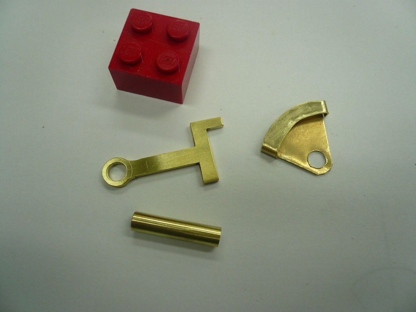
There are two lever types.
P1060893.jpg


The top of the lower lever will be cut off. I left it long so I’d have more widely spaced holes to use as locators in the mill.

The next step is to round the lower end.
P1060901.jpg


and drill it out to 5/32”.
P1060904.jpg


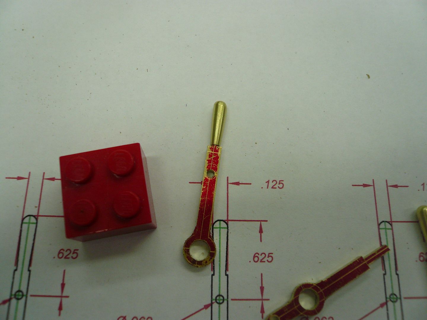
The upper end of the lever is rounded with a file to accept a handle.
P1060909.jpg


The handle is a piece of 1/8” rod with the end drilled 1/16” and tapered with a file.
P1060915.jpg


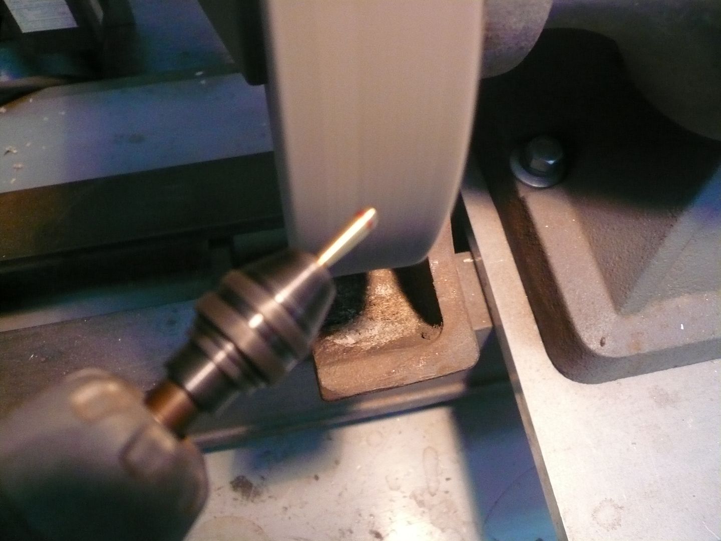
The top of the handle is rounded by inserting a slightly knurled piece of 1/16” rod into the handle and mounting it on a Dremel. The spinning part is then held against a 3-M deburring wheel to round it.
P1060917.jpg


The handle slips onto the lever and is soldered in place.
P1060926.jpg


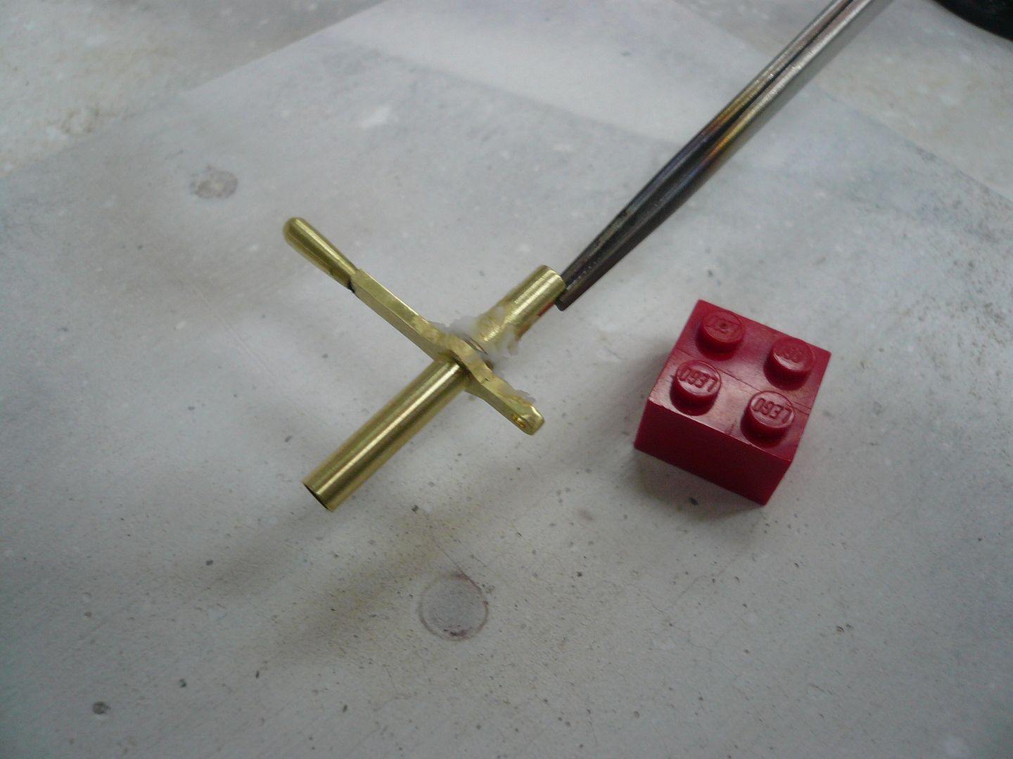
The movement of two of the levers is limited by what on a real tractor is a latching mechanism. I don’t know what their correct name is. I simulated them from a piece of .016” brass.
P1060931.jpg


P1060932.jpg


The levers and latches were soldered to a piece of 5/32” tube (1/8” ID) so they could be mounted on the shaft between the horn plates and have some stability.
P1060935.jpg


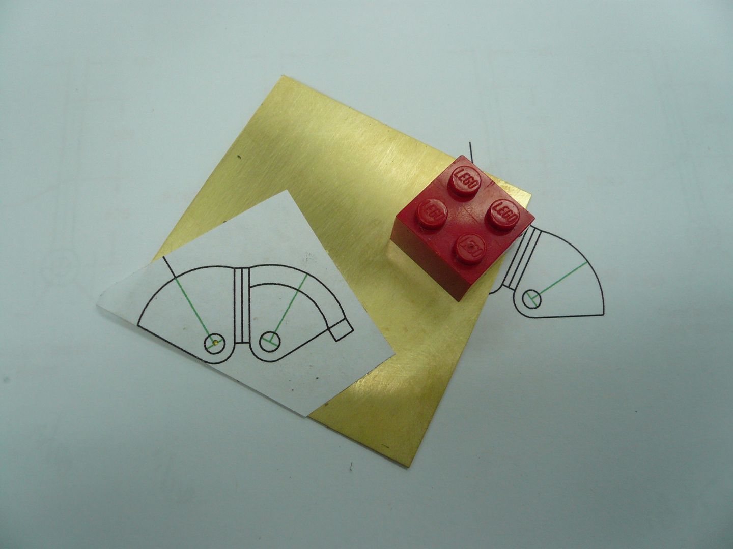
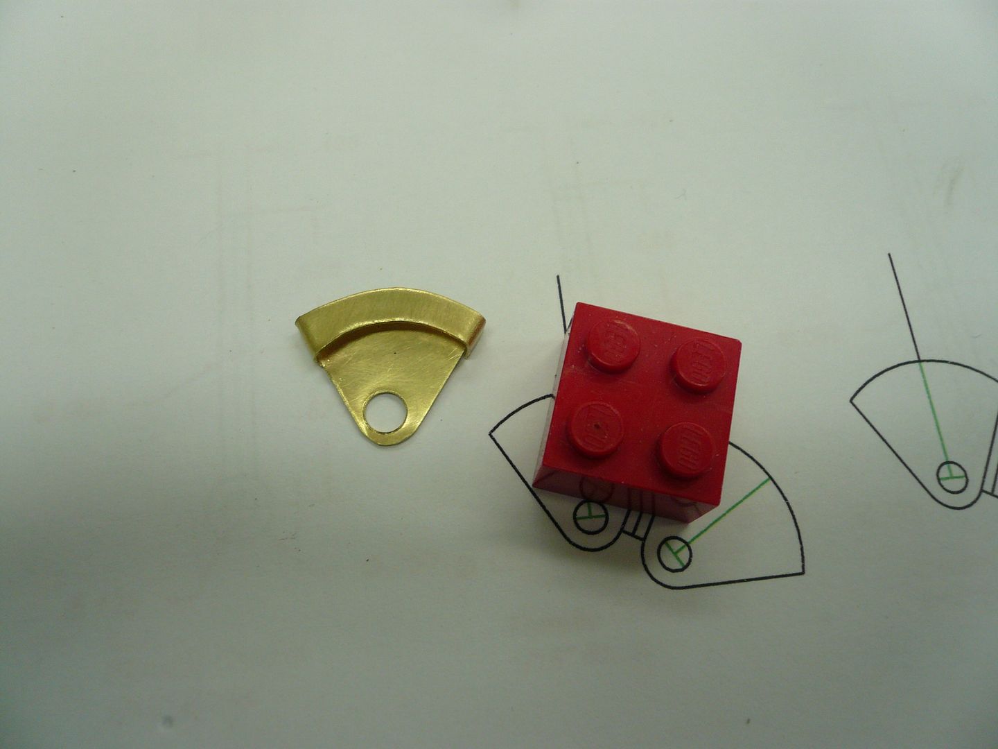
One additional piece was necessitated by poor planning on my part. The reverse lever needs to be held in position on the 1/8” shaft. If I’d have thought this through earlier in my build I would have drilled some holes in the horn plate to do that. As it is, the only way I could come up with to hold the left (reverse) lever upright was the odd piece shown below.
P1060937.jpg


It and the simulated latch are soldered to the tube. The odd shaped piece then locks on one of the bearing blocks.
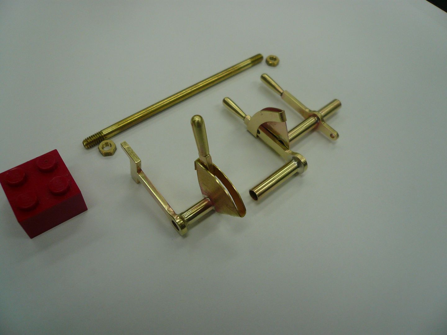
Here are the lever parts the way they’ll be mounted.
P1060940.jpg


The reverse (left) lever moves freely but doesn’t do anything. Its movement is restrained by the latch mechanism which is anchored to the bearing block. The throttle (center) lever actually controls the throttle and is restrained by the latching mechanism which is soldered to the clutch (right) lever which will be restrained by a rod attached to the lower end. Whew!!

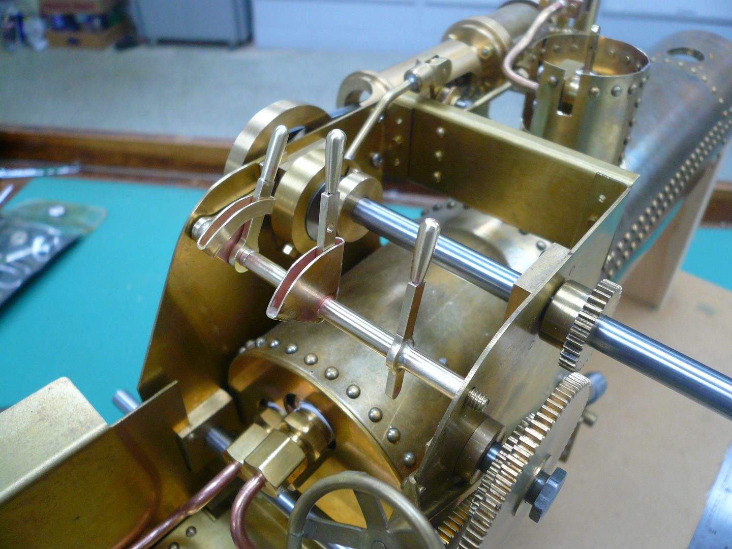
Here they are in place.
P1060943.jpg


Thanks for following along.

Dennis
 
Hi Dennis,
Once again I must say how nice and clean your work is. Is the right lever stationary so that it holds the quadrant for the middle lever?
George
 
Aw gee Dennis...that last photo is a winner. That should be seen in a book.
Wonderful stuff. I hope someday to produce that kind of work. Just awesome.
 
You are such a good modeler, Dennis. Very fine work!

Dean
 
Zee & Dean...Thanks.

Is the right lever stationary so that it holds the quadrant for the middle lever?

George,
Quadrant!! Thank you. It was really bugging me that I couldn't remember the name of that part. And yes, the right lever and quadrant are stationary so they limit the movement of the throttle control.
Dennis
 
THAT. is extremely beautiful work on display, Dennis. It seems that there HAS to be a way to incorporate engine reversing and a clutch mechanism to those dummy levers but I am too mentally challenged to come up with any ideas. :'( Whenever I see this title in the new posts section it is the very first one that I go to just to see get a glimpse of what you have done. VERY nicely done.

BC1
Jim
 
Hi Dennis
I have been looking through the thread at your build. It is excellent.
Jack B
 

Latest posts

Back
Top