Building Rudy's Steam Tractor

Home Model Engine Machinist Forum

Help Support Home Model Engine Machinist Forum:

This site may earn a commission from merchant affiliate links, including eBay, Amazon, and others.
Thanks for the gear info. "Ghart3" also modded his tractor to slow it down. He was kind enough to check the ratio on his (check his posts, lots of good info) and PM it to me. Here are some data points for you:

Overall Gear Ratios flywheel to wheel (if I've done the math right!)

23:1 Rudy's as built
37:1 DougLanum
43:1 ghart3

Gears are pricey, so it's good to have some flexibility when you go to order them. Check different combinations because the prices can vary a lot with only a slight change in pitch diameter. If you can design to use discontinued (but still in stock) gears they're really cheap.

Dennis

 
So, Ghart3, if you read this, could you supply us with the gear teeth and PD of the gear sets that you used in your build? As has been stated, gears are pricey and finding a better, read: more commonly used gear(s) is a much better alternative, not to mention the scaleness factor. ;D
 
Bearcar1, sorry not much help. Having gear cutters I just cut the gears according to Rudy's plans and just cut a couple more for more reduction. Mine was a change after built. Think Dennis's plan of hunting around for the best deal on gears and then fitting them to the tractor might work for you also.

Still have short piece of tubing with case "cast" on it that could be used for fake heat exchanger. Freebie to first person asking for it. Gary
 
Say Gary, I would be interested in that faux heat exchanger tube. I read the thread and liked the way it was arrived at but like so many other things, would have had to procure several other items in order to fabricate the end results. I'll be more than happy to reimburse the postage and whatever else in order to compensate for your hard work.

Jim B.
 
Flywheel

Finished the flywheel. I’m pretty stoked because I was able to use this surplus fitting.

P1030466.jpg


That I found here.

IMG_0121.jpg


A buddy turned me on to a local marine salvage yard. All of the above fittings are either brass or bronze and are sold by the pound for not much over scrap prices. Sweet. If you’re near water, it’d be worth scouting out any boat salvage places.

Forgive the diversion, back to the build.

The scrap fitting yielded a flywheel OD of 2.460” and an ID of 2.200”. Rudy’s plans call for 2.250” and 2.125”. Rudy’s plans also call for 1/8” diameter x 1/8” long tenons on the end of the spokes that fit into the hub. I eliminated those and inserted the 3/16” spokes into 3/16” holes in the hub. Worked fine.

The flywheel uses the same build process and fixtures as the wheels only with the templates modified to reflect six spokes. After soldering and trimming the spokes, true the flywheel on the lathe. Rudy suggests doing this on a mandrel between centers, but I don’t have a faceplate, so I turned a snug fitting 1/4" arbor and did all the truing operations without moving the arbor in the 3 jaw. The flywheel is held in place with the mounting set screw.

P1030563.jpg


Sequence was: true the outside, then first edge and then inside. Remove flywheel from the arbor and reverse. True the second edge and inside.

I’m less than thrilled with the appearance of the solder on the hub, but the balance is so good that I hate to mess with it.

P1030571_edited-1.jpg


Dennis
 
Dennis,

Very nice Flywheel.

I too cut my own gears.
It became part of my learning process of working in a machine shop while in college.

More photos to follow soon.

Doug
 
I'm jealous of you guys who can make your own gears. I'd like to see a thread on this sometime.

Here's where I'm at on the build.

Boiler Outer Casing

It feels like progress to finally be finished with wheel assemblies.

The boiler outer casing is the biggest part on the tractor and will push the limits of my equipment. Because of that I decided to use brass instead of Rudy’s suggestion of steel. The casing uses a 10 11/16” piece of 2” nominal pipe. Fortunately the local plumbing supply was willing to sell just a foot.

P1030575.jpg


The brass is 2.375” OD and 2.067” ID. The same as the specified steel pipe.

The pipe had to be cut to length and the ends faced off. As you can see, this was all my lathe could handle. Another 1/32” OD and the pipe wouldn’t have fit in the steady rest. Slow and easy was the way to go.

P1030605.jpg


P1030604.jpg


Rudy suggests marking out four longitudinal, equally spaced lines on the outside of the casing to use as reference lines. I did this by mounting the casing in the lathe and using its indexing ring and the carriage to lay out the lines. I might have used a little more layout fluid than necessary.

P1030614.jpg


I then layed out all the holes and proceeded to the drill press. The openings for the smokestack and steam dome are 5/8”. I modified the drill bit to drill brass (there’s a thread on this, but I couldn’t find it) and ran the drill at its lowest speed. This is a big hole and brass likes to grab, so I clamped everything in place. No hands. Drilling went fine.

P1030648.jpg


The steam dome opening calls for two 5/8” overlapping holes. I drilled the first hole and then decided I wasn’t comfortable trying to drill the second one.

P1030653.jpg


So I mounted the casing in my Sherline mill.

P1030658.jpg


And milled the opening using a 3/16 bit and very light cuts.

P1030662.jpg


I ended up with a D shaped opening, but it looks okay and it will be covered by the steam dome.

If I had it to do over, I’d chain drill the opening and then finish the edges with the mill. That or find a buddy with a big mill.

Dennis
 
Boiler Casing (Continued)

Rudy’s engine has a row of rivets running longitudinally on the right side and in a ring around the boiler. They’re there for appearance and represent the boiler plate joints on a real engine. Rudy spaced his 0.250” apart. To be a little closer to scale, I decided to use a double row of rivets and to position them at about 10 o’clock. I’ll be using 1/16” rivets, so the holes will be drilled with a #51 drill. Here’s my rivet spacing:

RudysSteamRivetLayout.jpg


In order to keep the rivets in a nice line, I drilled the longitudinal ones on my Sherline mill. I spot drilled first, then through drilled.

P1030736.jpg


P1030737.jpg


The front ring of rivets was done on the drill press. The wood fixture keeps them in a nice line. Again, I spot drilled and then through drilled.

P1030743.jpg


The last step was to cut away the piece of the casing where the firebox goes. A little clean up and the boiler casing is complete and ready for rivets.

P1030761.jpg


Dennis
 
Dennis I don't know anything about the plans you are working from.
Is the outer housing a pressure vessel?
Brass may not be a good choice.

Rick
 
Dennis,

That's an awful lot of very nice work, not to mention the cost of material.........but if that is the boiler pressure vessel then for your safety and the safety of your loved ones, please don't use brass.

May I suggest you get a copy of the model boiler code for your country and follow it religiously as to choice of materials and construction techniques/requirements.

Traction engine boilers are subject to additional loads and stresses due to their carrying the front axle and steering mechanism.

Please be very careful, model boilers can maim and kill as readily as their big brothers.

Sorry if I've spoiled your day.

Best Regards
Bob
 
Gentlemen, what Dennis is working on is merely a 'boiler casing' that is actually window dressing. The true pressure vessel will be fabricated from copper and will be housed inside this casing, it will not be subjected to steam pressure at any time. BTW, Dennis, I like the way you have created the double row of rivets as in full scale production.

Jim B.
 
bearcar1 said:
Gentlemen, what Dennis is working on is merely a 'boiler casing' that is actually window dressing. The true pressure vessel will be fabricated from copper and will be housed inside this casing, it will not be subjected to steam pressure at any time. BTW, Dennis, I like the way you have created the double row of rivets as in full scale production.

Jim B.

That's the answer I was hoping for!
The work is date is far too nice to be scrapped.

Rick
 
Guys,

I appreciate your concern, but as Jim (bearcar1) says, it's just a casing. The Village Press plans I'm using have detailed instructions for the boiler as well as numerous safety cautions. It's a proven design as many of these engines/boilers have been built to these plans since 1971.

That said, when I get to the boiler fab I'll be showing lots of pictures so if you see anything that causes concern regarding safety, please let me know.

Best regards,
Dennis
 
Dennis,

Phew ;D ;D ;D

I'm so glad that's cleared up. :bow: :bow:

On with the show.

Best Regards
Bob
 
Earlier Doug Lanum posted photos of changes he made to his tractor. Recently he sent me some additional photos. I thought everyone should see them and got his permission to post them here. He says he'll be happy to answer any questions. The mods include an improved crosshead design, addition of a whistle and a nifty draft fan.

The crosshead design was changed to match a more prototypical design.
It is close to what Case used and is a more sturdy design.
It is made of brass, and photos will follow soon.

We also made small fans to put on top of the stack while building pressire.
We found that the alcohol burners had flame going everywhere, so the fan keeps the fire going the right direction. It also allows the steam pressure to build much quicker.
once pressure is built8 up, and the engine is running, the engine exhaust provides sufficient draft.
This fan is made with a simple bent blade impeller and a small 1.5 volt. motor.

DougLanum4.jpg


DougLanum5.jpg


Newcamera276.jpg


Newcamera278.jpg


Newcamera279.jpg


Newcamera281.jpg


Newcamera282.jpg


Newcamera284.jpg


Newcamera286.jpg


Newcamera289.jpg


Newcamera292.jpg


Newcamera297.jpg


Regards,
Dennis
 
Continuing my build....

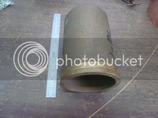
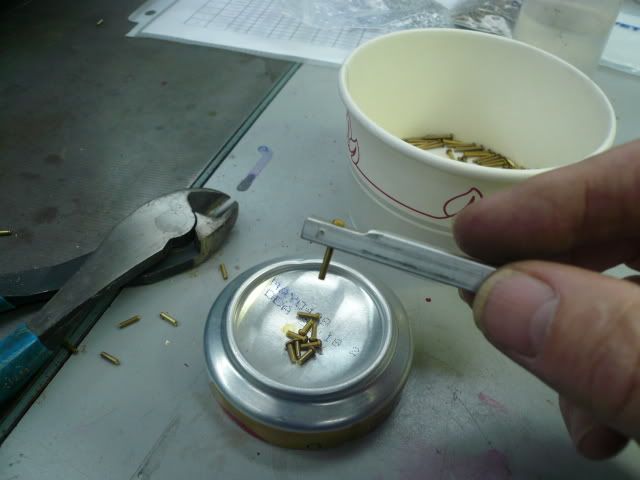
Boiler Casing Rivets
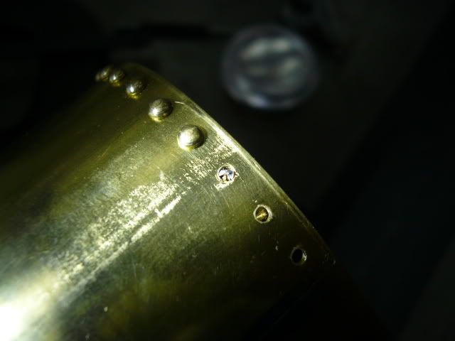
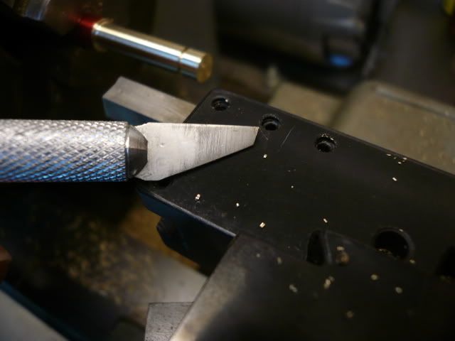
I’m using 1/16” solid brass round head rivets. The rivet place had a 1/4 lb. minimum (about 600 rivets) so I just bought the longest (1/2”) and will cut as needed. To cut, I drilled a hole in an appropriate thickness of material and snipped the rivets with a side cutter. The side cutter leaves a V shaped tip, but that flattens when the rivets are set.

P1030765.jpg


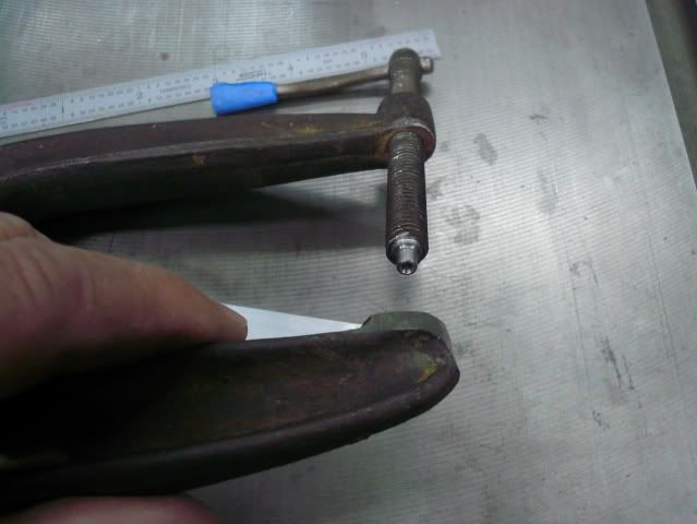
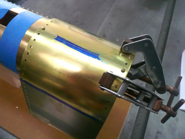
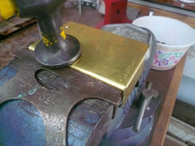
Setting the side rows of rivets requires a tool that can reach in about 4”. To do this, I modified an old C clamp by cutting the handle and foot off and then mounting the screw in the lathe and drilling the end with an 1/8” ball mill.

P1030730_edited-1.jpg


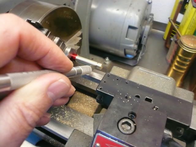
To set the rivets, insert a rivet and screw the clamp down until the rivet is set. It's very helpful to make a stand to hold the boiler casing in place during riveting. It helps on those many occasions where you need three hands.
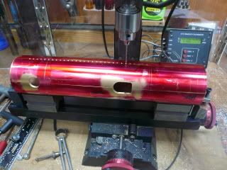
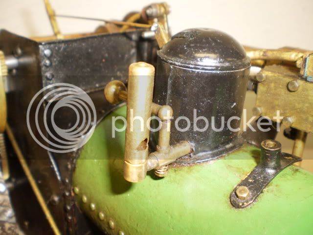
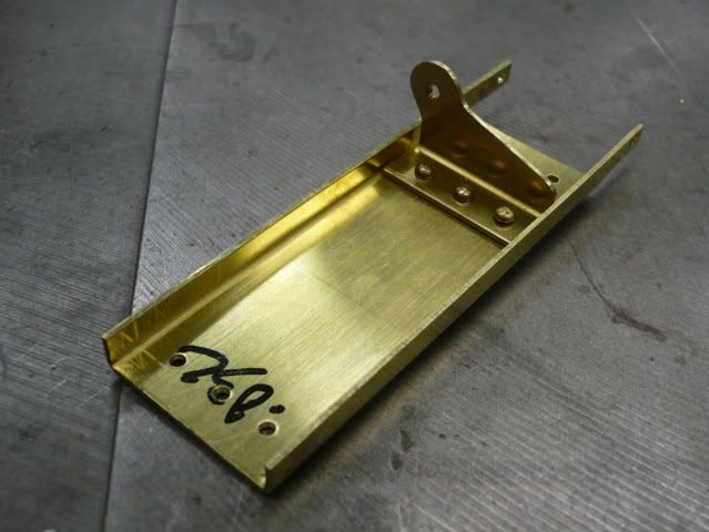
P1030769.jpg


Firebox Wrapper

Rudy’s plans call for 1/32” steel for the wrapper. In fact, he used sheet steel throughout his build. I plan to use brass because I happen to have a nice piece of .032” brass on hand and because I'd rather work with brass than steel.

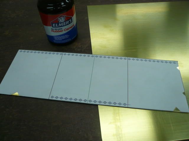
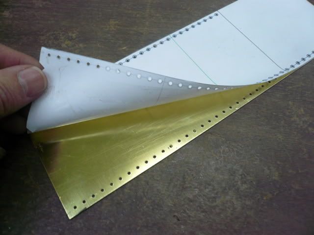
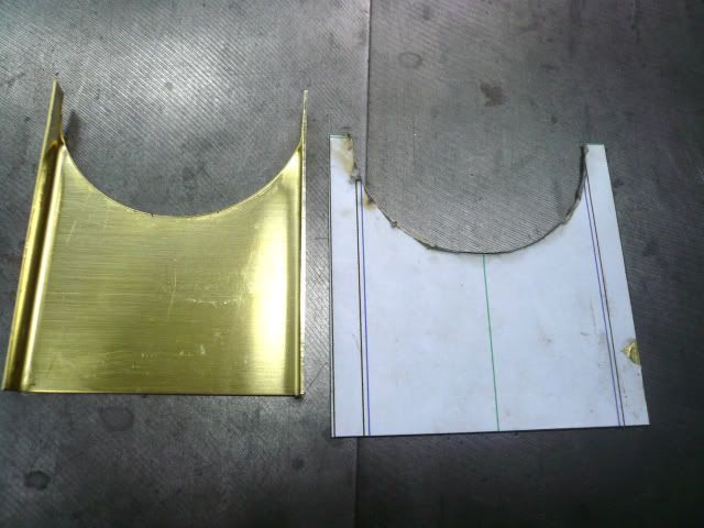
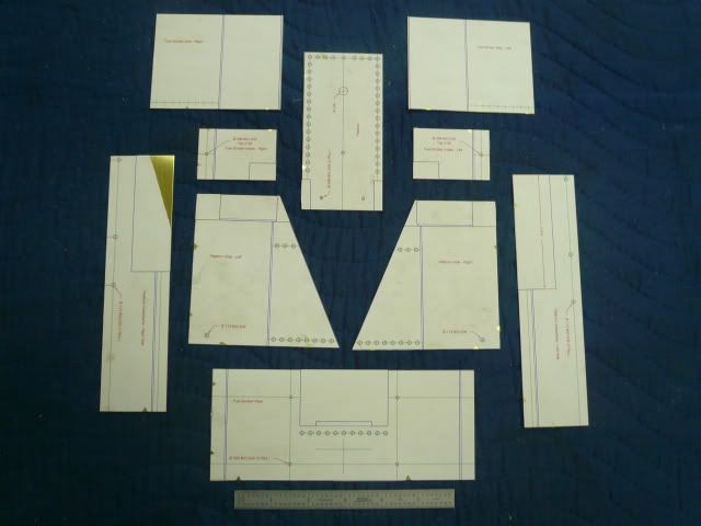
I layed out the wrapper and rubber cemented a copy to a piece of brass sheet, sheared it to size, drilled the rivet holes and prick punched the reference lines.

P1030749.jpg


P1030751.jpg


This paper & glue method might be suspect for precise machining operations, but it seems to work well for sheet metal layout.

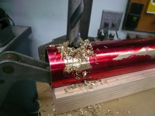
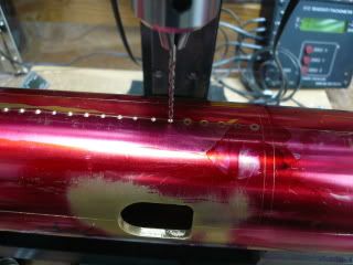
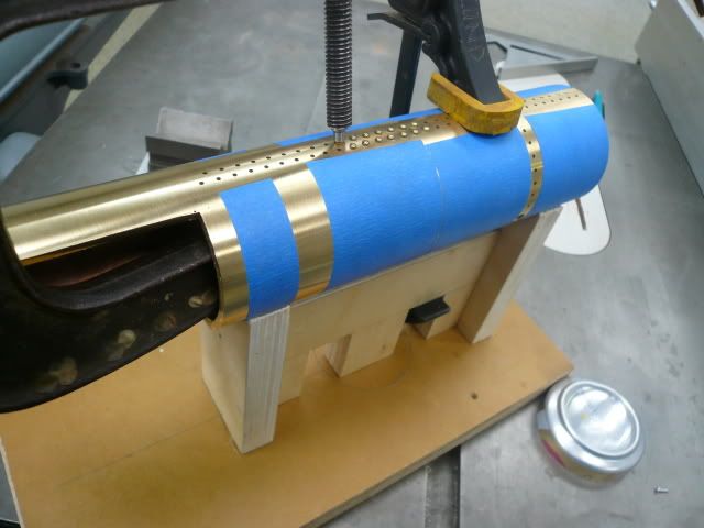
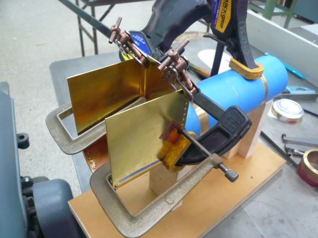
After forming the wrapper, I clamped it in place on the boiler casing (this is where the reference lines Rudy suggested really come into play, because it’s important that the center of the wrapper be at top center of the casing). Then I drilled and set two rivets, moved the clamps down, drilled and set another two rivets and so on until the wrapper was in place.

P1030778_edited-1.jpg


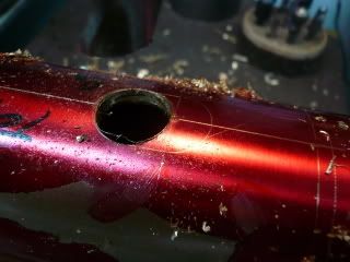
This operation was not without its problems. That’s a broken off drill bit.

P1030784.jpg


I broke two before I figured out my fixture had just enough wiggle to stress the bit. No problems after I fixed it. Fortunately, I was able to get both bits out by grinding a little on the back side and punching them out.

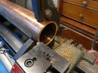
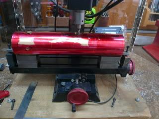
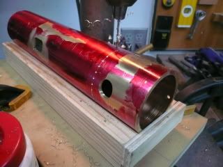
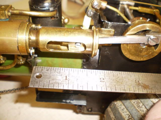
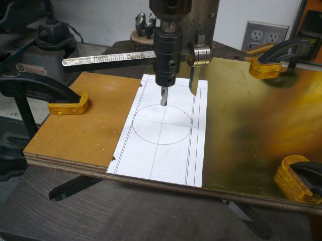
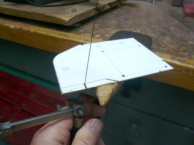
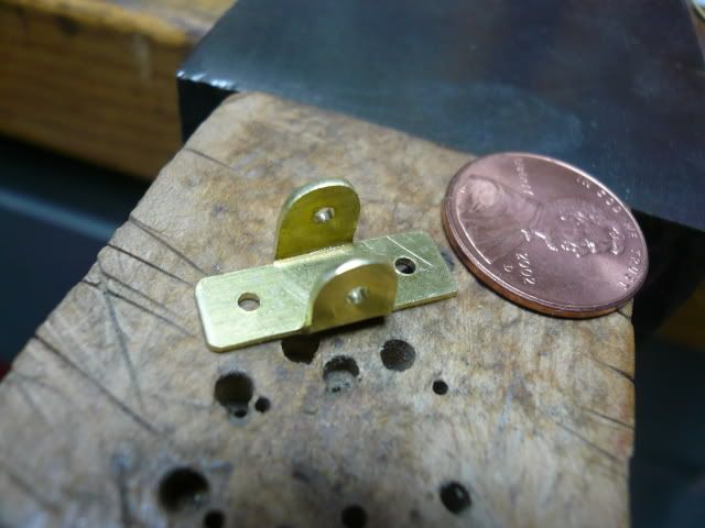
Firebox Throat Sheet

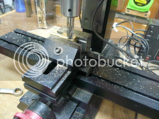
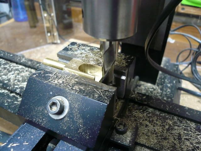
The firebox throat sheet encloses the front of the firebox and is contoured to hug the bottom of the boiler casing. I made it using a fly cutter in the drill press. Note that the pattern is glued to a larger sheet of brass that is in turn clamped to the drill press table. No hands anywhere near the fly cutter or the work for this operation.

P1030755_edited-1.jpg


One advantage of using the fly cutter is that you end up with an extra throat piece (and yes, I screwed up the first one and needed the second).

P1030763_edited-1.jpg


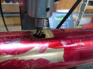
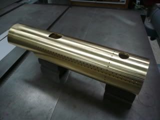
The throat sheet is riveted to the firebox wrapper. I clamped it in place and line drilled and installed several rivets, then removed the clamps and finished up. There’s an old woodworkers saying that you can never have too many clamps. Looks like it applies to model engineering, too.
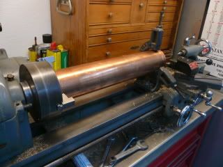
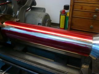
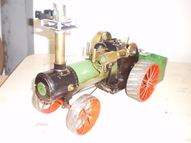
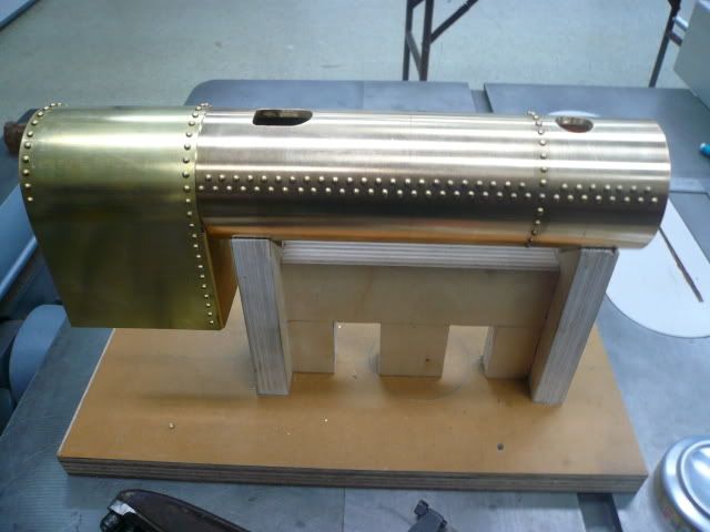
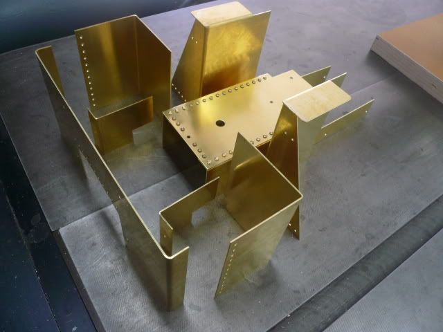
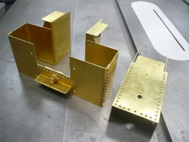
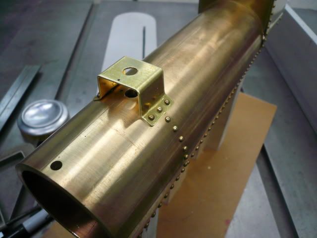
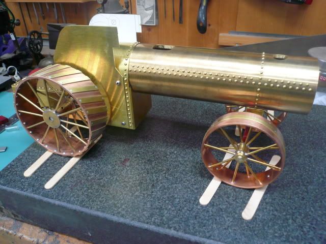
P1030790.jpg


Here’s the finished boiler casing and firebox subassembly.

P1030797.jpg


Dennis
 
Dennis,

Beautiful work. :bow: :bow:

Best Regards
Bob
 
Wow, that's gonna be a FINE looking boiler. Great work.

Chuck
 
I thought I’d posted this earlier, but guess I hadn’t. The original Popular Mechanics (1971) article on Rudy’s Steam Tractor is here. (Kermit, thanks for your post earlier today...I've always wondered how to insert a URL and rename it!)

The sketches do a good job of showing the copper boiler nestled inside the boiler casing.

Sheet Metal Fab

Sheet metal parts are of .032” brass. Here they are sheared to size but without the notches cut out.

P1030807.jpg


The notches need to be sawed out or cut in a way that doesn’t distort the metal. A hack saw, jeweler’s saw and file worked pretty well.

P1030845.jpg


Forming the parts is a matter of finding the right pieces of steel and clamping them in a vise. Fortuneately none of the pieces are overly long and only the platform sides have bends in two directions. This photo shows bending using a body hammer, but I found that a rawhide mallet is a much better tool. The body hammer tends to leave dings and the mallet doesn’t.

P1030827.jpg


Formed sheet metal parts.

P1030833.jpg


And here they are assembled into two of the three major body assemblies (the boiler casing is the third).

P1030850.jpg


The jewelers saw/file work pretty good for the fiddly sheet metal.

P1030800.jpg


P1030805.jpg


This Motion Support Plate is built per print but will be modified as required to implement Doug Lanum’s improved crosshead support.

P1030853.jpg


Here the boiler casing is upside down to show the Perch Bracket (supports the front axle fork). It’s a form and fit part that’s riveted to the boiler casing. A long rod inserted through it and the hole in the boiler casing helps with alignment as you want the fork to be perfectly vertical once the tractor is on its wheels.

P1030851.jpg


I think that’s the last sheet metal for awhile…for a machining site, it seems like a long time since I’ve machined anything. Thanks for bearing with me.

Dennis

 
Front Axle Fork & Front Axle

The front axle fork and front axle are pretty much just straight machining jobs.

P1030889.jpg


The front wheels are held on the axle with external circlips which require a 0.025” groove. I cut the grooves using a modified x-acto blade.

P1030601.jpg


First grind off the blade, then shape the tip. The tool is used freehand using a ¼” tool bit as a T-rest. Manipulate it like a parting tool on a wood lathe. The technique came from a clockmaker’s video. It works great on brass and aluminum for parting off small bits.

P1030592.jpg


The front axle fork is a cylindrical turning with flats machined on each side.

P1030876.jpg


A 5/16” slot forms the fork. I cut the slot full width by taking lots of very light passes.

P1030880.jpg


Once the front axle was complete, I couldn’t resist putting it on its wheels.

P1030856.jpg


Still a long ways to go, but I’m feeling like I have a fighting chance of getting there. Can’t wait to get it running.

Dennis
 

Latest posts

Back
Top