90 degree V-twin engine

Home Model Engine Machinist Forum

Help Support Home Model Engine Machinist Forum:

This site may earn a commission from merchant affiliate links, including eBay, Amazon, and others.
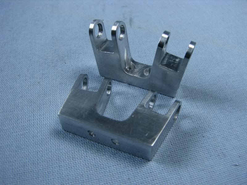
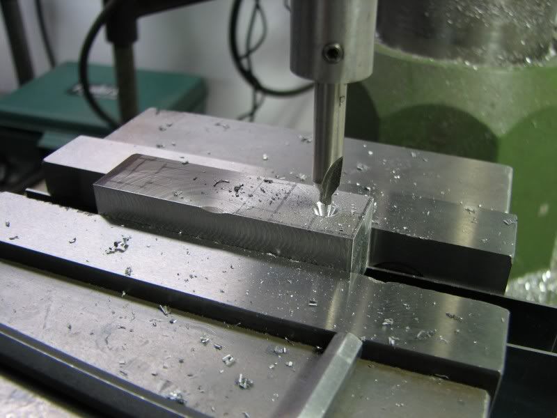
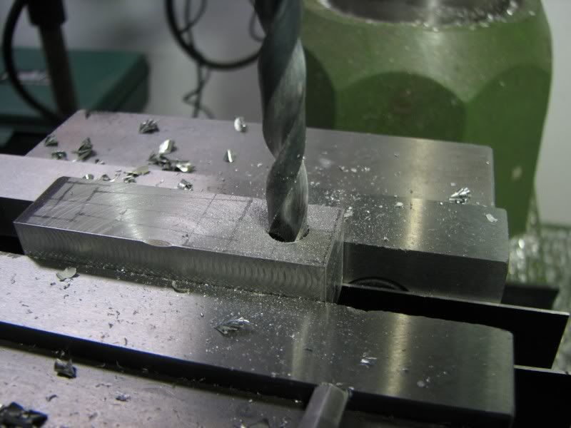
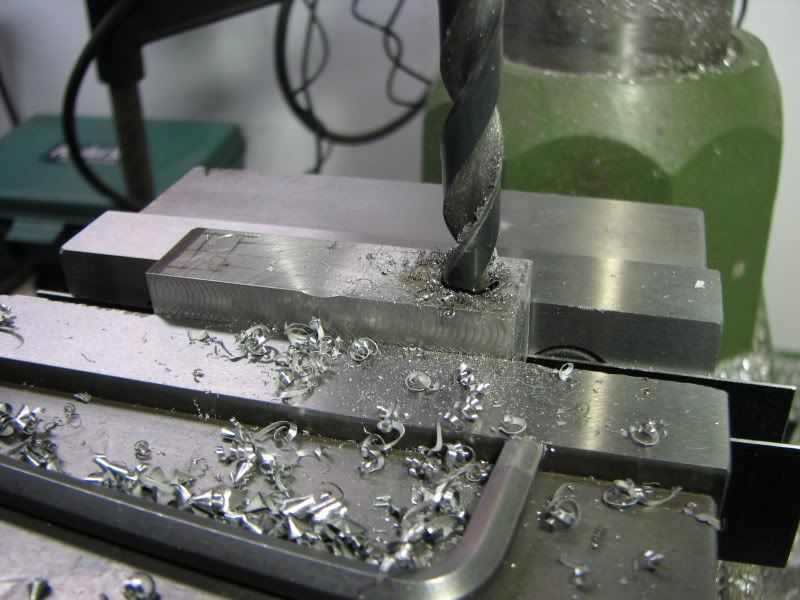
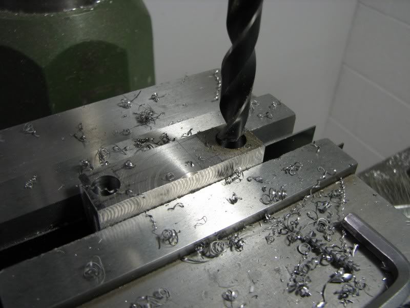
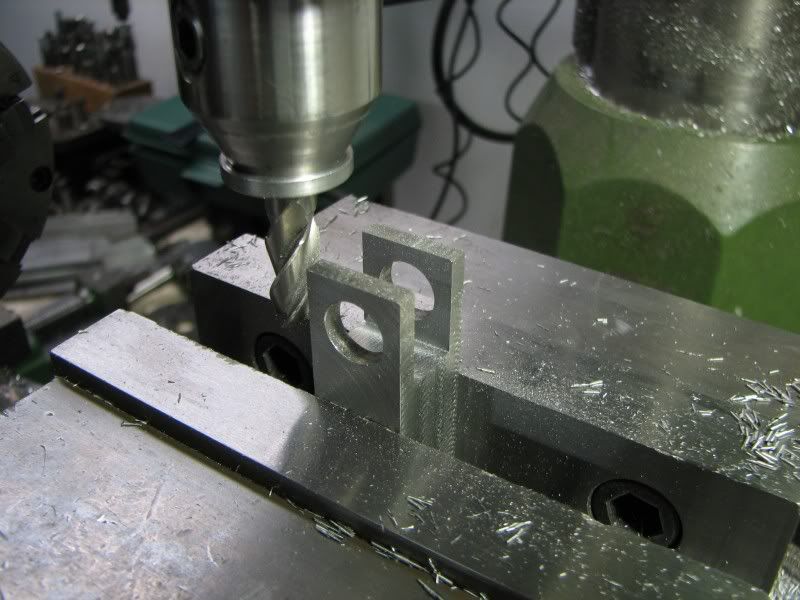
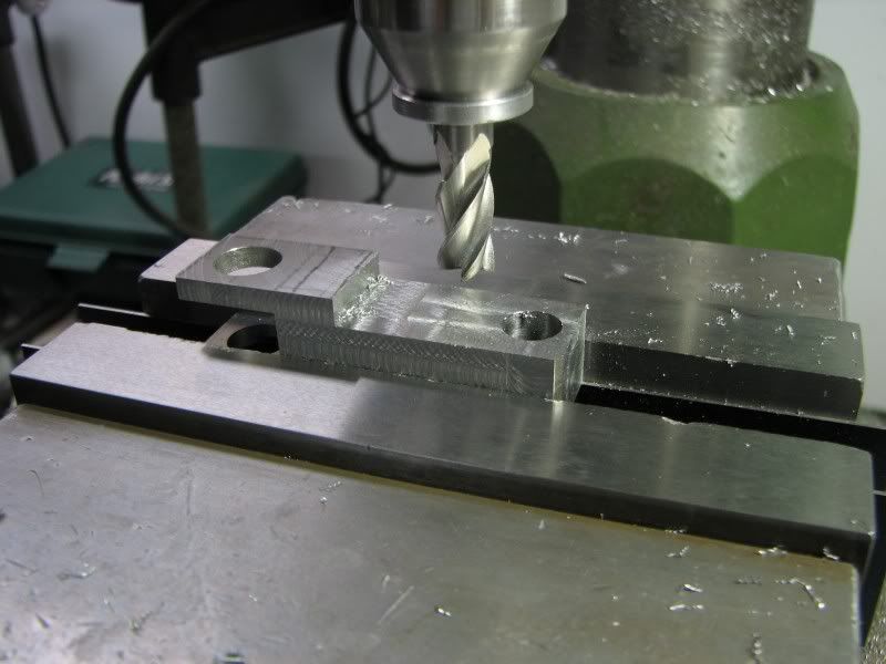
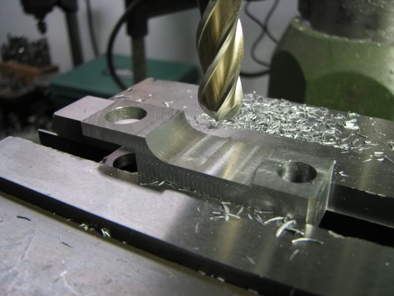
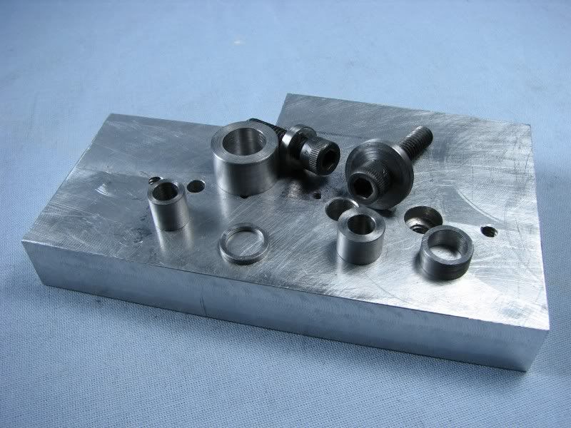
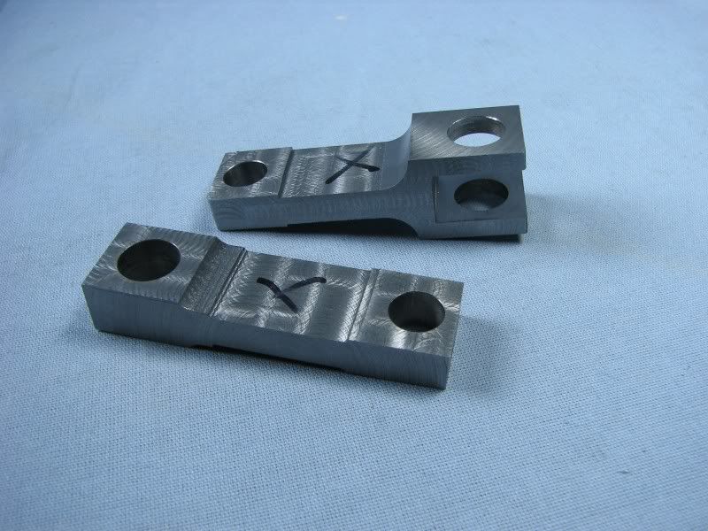
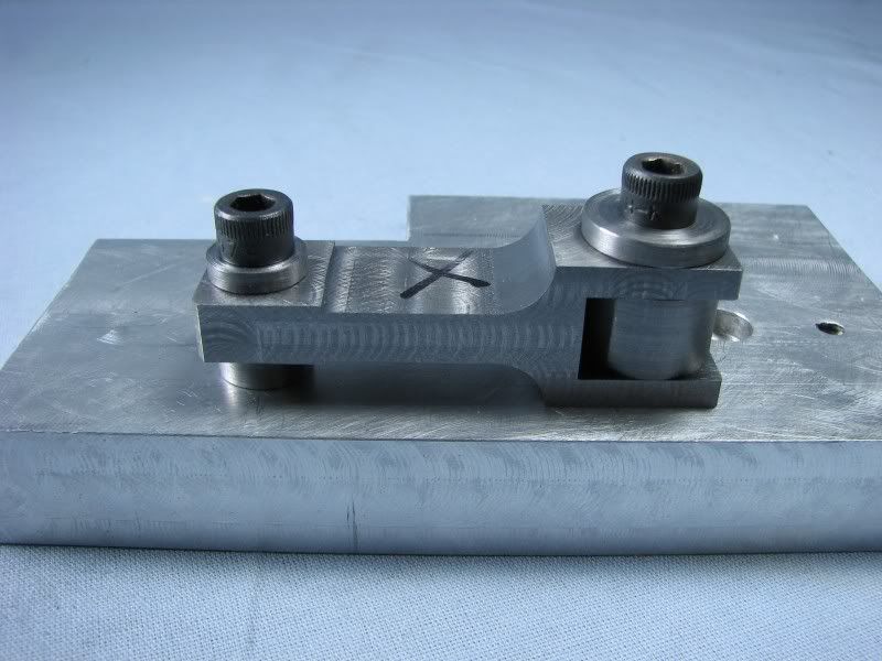
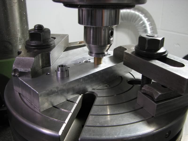
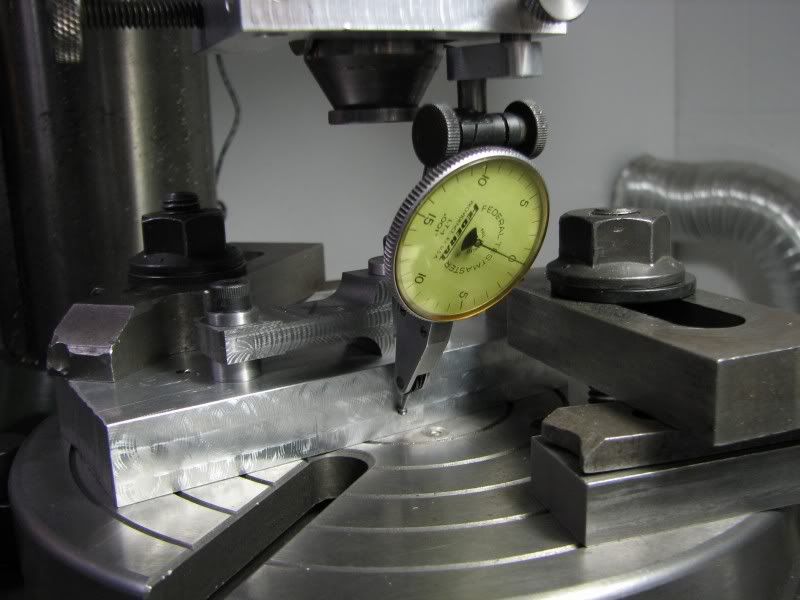
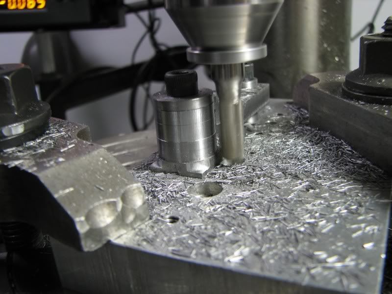
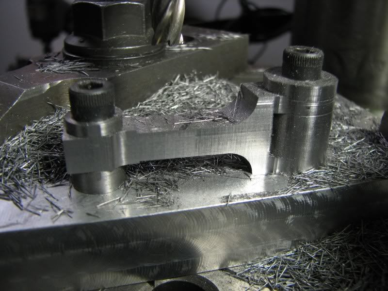
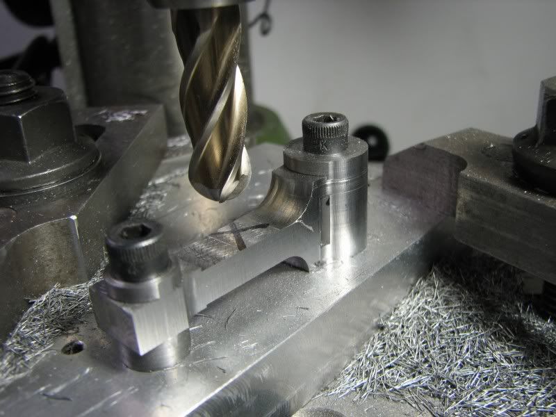
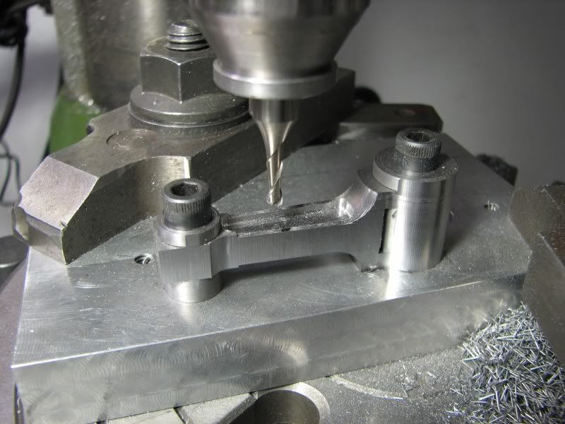
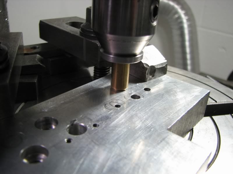
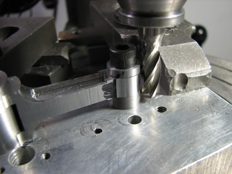
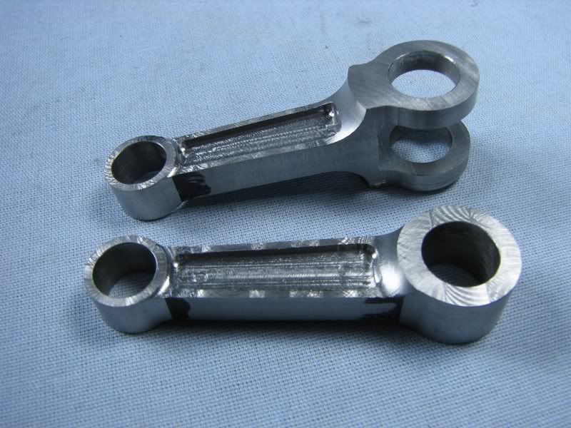
In the last installment I had cut the rocker arms off of the stock. I was getting ready to drill them and I noticed that their proportions were a little different than the drawing. After a quick measurement I realized what I had done. I used a .50 piece of stock and when I flipped it over to cut the large radius on the top I had forgotten to take the extra stock off before cutting the radius. I made up this little fixture to locate the arms for cutting the radius down and also for putting the drilled hole in. I then used the back side of the fixture to put the ball socket in for the end of the pushrod.
EU.jpg

EV.jpg

EW.jpg
 
With that out of the way I turned up a mounting mandrel on the lathe. I then mounted the arms on it and took .031 off of each side. Now the hand work begins. As with the other parts a lot of grinding, filing and sanding to finish them up. Probably about half as much time as all the machining took. Anyway these are finished. I just have to make the bronze bushings but I'll do all of them for the whole engine at one time.
gbritnell
EX.jpg

EY.jpg
 
George, you are truly a master at the "hand work". Your work looks as if you really get a lot of enjoyment from the filing and sanding!

Chuck
 
I love the results of your hand work, George.
These look great!

Dean
 
Just can't believe the amount of work in those! :bow:
 
I just got two pieces made up today. A lot more work than meets the eye. I made the profile in one piece and when I had the rest of the machining done I cut them in half and then cleaned them up. Tomorrow I should get the pivot bolts, nuts and adjusters made up. That will take care of the upper valve train.
gbritnell
EZ.jpg
 
Sensational, Beautiful handiwork.

I try to stay away from the forums as much as I can, (during a project) so I can spend more time on my projects, or else I get swallowed up browsing in the variety of great threads on these forums, and spend less time actually building,

However I visit this thread for educational purposes, you inspire me to start learning how to make, barstock material parts look like castings, professionaly finished and polished, as if they came out of a mold, because I only work from bar stock, (scratch), that's my endever in this hobby, scratch building, and your thread is a

WEALTH of instructional educational material, that is guaranteed to make us all better at our hobby.

Thanks for doing an excellent job on sharing your methods with this build thread.

 
Hobby
You just said a mouth full....LOL. You and me, both.

Steve
 
Those two pieces look like a great deal of work to me, George.
They look great.

Dean
 
Gentlemen, here's today's installment. It's quite lengthy so hang in there. In this section I am machining the connecting rods. They are a fork and tongue type. I am making them out of 12L14 steel and they will have bronze bearing inserts.
I had a piece of 3 inch round stock that had a slice taken off of it. I needed .75 and luckily it was .79. I layed out the rods on the surface and then bandsawed the stock off. The first couple of pictures are center drilling and progressively drilling up to the desired size.
FA.jpg

FB.jpg

FC.jpg

FE.jpg
 
The next operation was to cut the material out of the forked end of the one rod. As I progressed I figured I wouldn't have anywhere to hold it securely so this step came next.
FF.jpg


I then started taking the rods down to the finished thicknesses. I am only showing the forked rod in these sequences as the machining is the same for both.
FG.jpg

FH.jpg
 
I had a machining fixture from another job and it still had room on it so I drilled, tapped and counterbored the required holes for this job. You can see the plate, bushings, spacers and screws required for this job. I have a box with many fixture plates and bushings that I have used over the years. Most of them I don't even remember what they were for but they certainly come in handy for new work.
FJ.jpg


In these pictures you can see the roughed out rods, both forked and tongue and one of them mounted on the fixture plate with the required spacer under the small end.
FK.jpg

FL.jpg
 
At this point I had to take my dividing head and vise back off of the table to set the rotary table up. The usual rough centering with a piece of stock in the spindle then indicating the center hole. I have to make sure I leave enough head room for the longest cutter that will be used or else the head has to be moved and everything reindicated. Darn round column mills! The next photo shows me picking up the big end counterbored hole. I have a selection of mandrels that will usually fit the size I need. The second picture shows me indicating the side of the fixture plate. I make all my holes parallel so that I have a reference should I need it. In this case I indicated the side of the fixture and set the dial on the table to an even number. I will need to rotate the rod to cut the side at about 2 degrees.
FM.jpg

FN.jpg


I started spinning the big end being careful not to go to far to the inside. After getting the radius to size I then rotated the table and started reducing the sides, sneaking up on the tangent point of the end radius. Even if the radius is heavy I can go back and rotate it a little farther until I get a nice corner. When I'm close I put marker ink on it so I can see where my cut is and how it's blending with the previous cut.
FO.jpg

FP.jpg


With that step finished I put in a .50 ball mill to spin the tangent radius on the top.
FQ.jpg
 
The next step was to cut the relief in the face of the rod. I used a .125 cutter with an .03 radius on the corner. I made an initial cut with the rotary table squared up, working down to the .05 depth and establishing the end dimensions. I then rotated the table back to the 2 degree angle for each side and cut till the outside rib was .05 thick. Once that was finished I squared the table back up and cleaned up the end cuts to match the angular walls. On this type of job there is no quick way. To get it right you just have to take your time and pick away at it.
FR.jpg


In this picture you can see the progress of all the work.
FS.jpg
 
With the same procedure carried out on both rods it was time to move the fixture plate to the small end counterbore. The same steps were required as the first hole with the exception that I didn't need to indicate the side of the fixture. Spinning the small end and cleaning up the beam with a radius cutter are the two final machining steps.
FT.jpg

FU.jpg


The last picture of this series is the fully machined rods. They will now go to the bench for usual filing and sanding. I will post a picture when they are done.
George
FV.jpg
 
Hey George, Thanks for posting that! I might try some of that on the con rods on my Mega Cyclone. I'll be starting those soon. Nice work!!!
 
OOOH nice rotary table lesson there George! Thanks!
:bow:
 

Latest posts

Back
Top