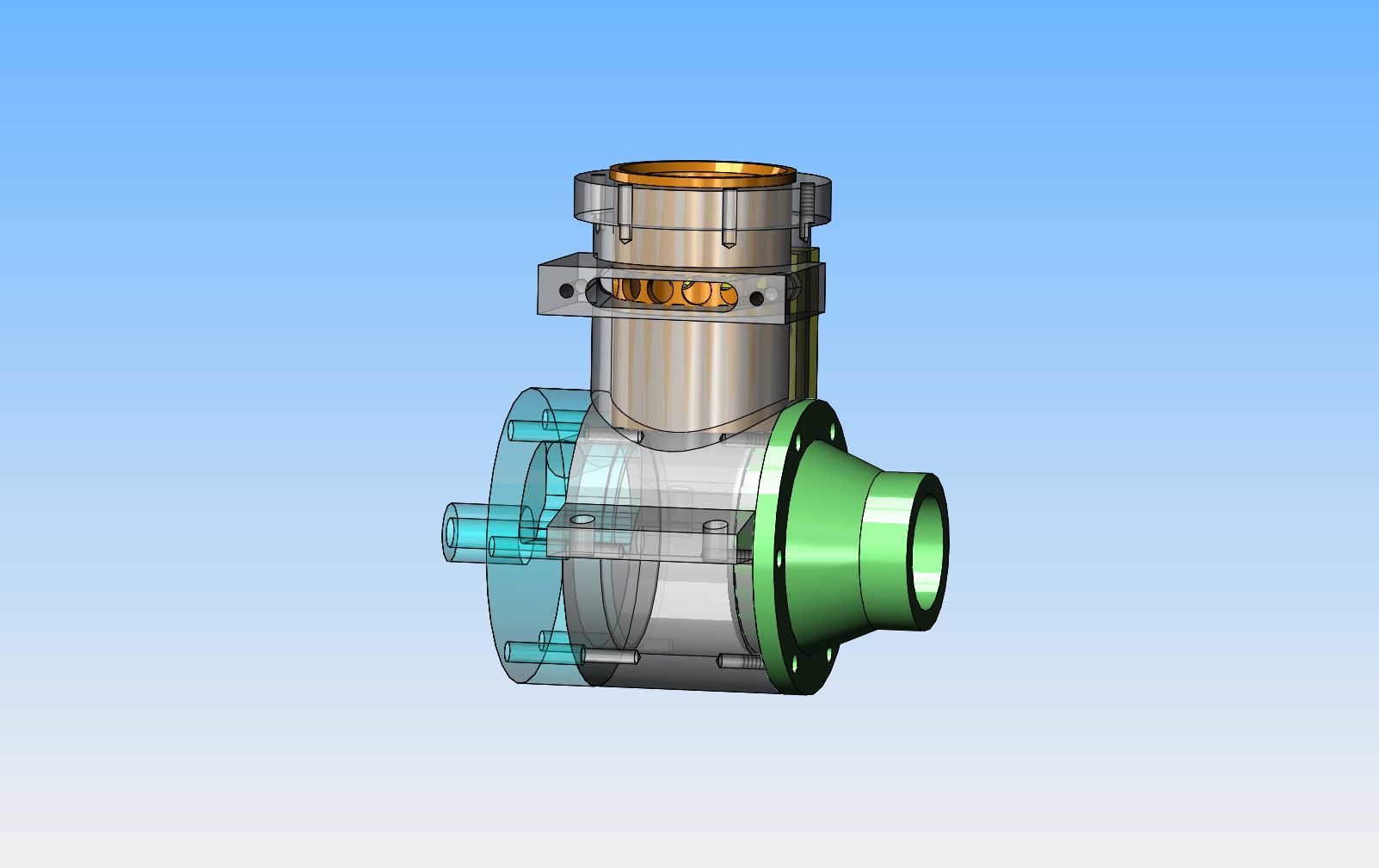
I am going to attempt to design and build a 2 cycle engine from bar stock, which uses no castings. I have spent a couple of days searching the internet for a 2 cycle engine which has a relatively low compression ratio, spark ignition, and can be machined using a conventional lathe and mill. I have found what I have been looking for, thanks to a member in the U.K., and although it is made from castings, it is a proven design so I know that the port layout positions are correct. The engine which I will be using as my reference is the "Wombat", originally designed by Edgar T. Westbury in the 1930's or 40's. My design is going to be a radical departure from the original designers, so I am not concerned about copyright infringement, however, I want to give credit where credit is due. This engine will have a 1" bore, X 3/4" stroke single cylinder configuration with ball bearings on the crankshaft. It will be machined from aluminum with a cast iron liner, and have (gasp) cast iron rings. It will have rotary valve induction. I am in no rush at all to get back into my machine shop, as I need some recovery time from 4 months of building my twin opposed i.c. engine. Stay tuned--This could be fun!!!---Brian
You are using an out of date browser. It may not display this or other websites correctly.
You should upgrade or use an alternative browser.
You should upgrade or use an alternative browser.
2 Cycle Engine from Bar Stock
- Thread starter Brian Rupnow
- Start date

Help Support Home Model Engine Machinist Forum:
This site may earn a commission from merchant affiliate
links, including eBay, Amazon, and others.
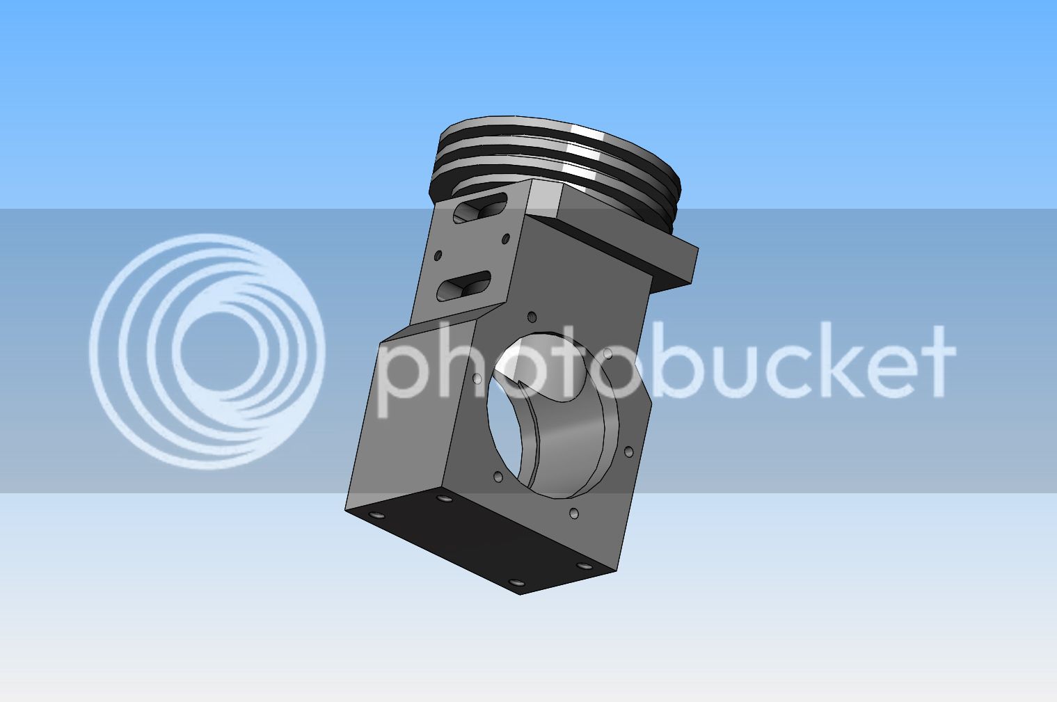
Yes, I know--looks pretty strange doesn't it!! This is "more or less" what the original casting would have looked like without the fins on it. It is correct in terms of bore, crankcase i.d. and size and positioning of ports. Now, I wouldn't try to machine this shape from solid in a million years. However, I have to model this main body, and then all the parts that fit into it as accurately as I can, just to determine to my own satisfaction how everything fits together and how all the parts interact with each other. After doing that, I will be able to determine how I can modify the body shown here to make it more "machineable friendly".


There!!! That'll do me for today. All of the other parts which I am modelling, although they too have the same critical dimensions as the cast and machined parts, are being greatly simplified as I model them. This is to make them easy to machine from solid. I have to enter all the math data as I model the parts, so I will pull my detail drawings directly off the parts when I get ready to detail them. Some of the parts may get a bit of cosmetic work if I think they look too "blocky" but I won't really have a good overview of that until everything is modeled. I have found one error on the old original drawings. The dimension from the top of the cylinder down to the center of the exhaust port on the cylinder is 21/32:. The dimension on the liner is 11/16" but it is taken from the top of the liner, not the underside of the 1/16" thick liner "lip". This puts the exhaust ports in the liner offset from the cylinder port by 1/32". I have changed the hole position in the liner to match the port in the cylinder.


canadianhorsepower
Well-Known Member
- Joined
- Oct 22, 2011
- Messages
- 1,671
- Reaction score
- 324
lohring
Well-Known Member
- Joined
- Aug 6, 2011
- Messages
- 440
- Reaction score
- 157
I built an engine like that in high school, but used a casting for the crankcase. Bar stock engines have been built by serious model car and airplane racers for years. Jim Allen's gallery shows his efforts with high performance 15 cc engines. (Sign in required) The late Wayne Trivin built his small engines from bar stock. Here is a description on how he does it.
Lohring Miller

Lohring Miller

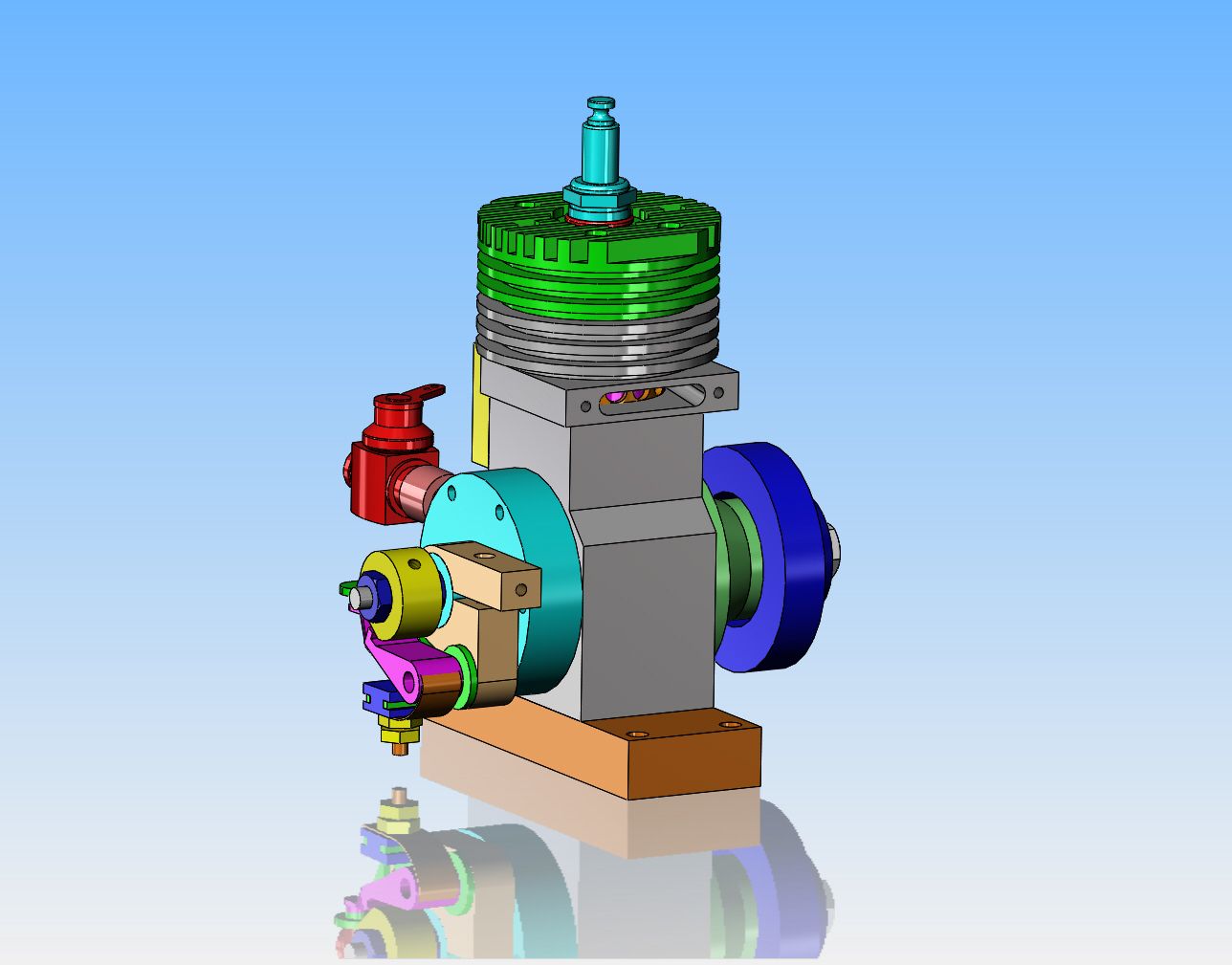
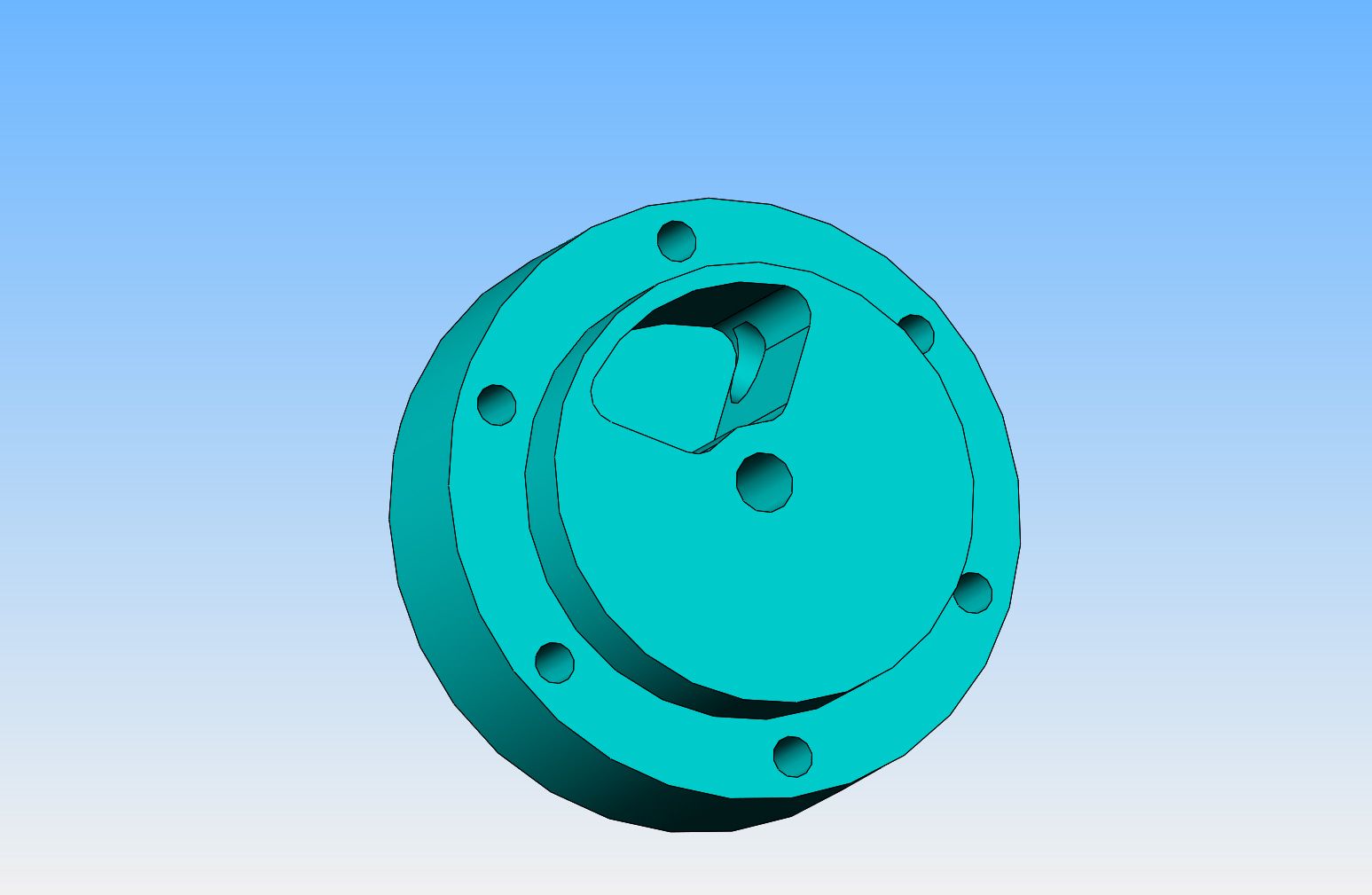
At this point I am beginning to get a much better understanding of how this two cycle engine works. The rotary valve is a new concept (for me). I still haven't redesigned the main body to make it more "machining friendly", but I have redesigned all of the ancillary parts to something that can be carved from bar stock on my lathe and mill. I haven't looked too closely at the ignition cam or points yet. I have an idea of how I am going to modify the cylinder head to match the upswept contour of the piston top--I just haven't done it yet.


This is what it looks like with the cylinder in "super simplified" form. All of the ports, bores, and bolt holes and mating surfaces are the same as the original model, and I have managed to squeeze in a few cooling fins. I can't make it any simpler than this and still make it from one piece and still have a chance to cool it somewhat. I did take the mounts away from the sides of the cylinder and add a separate baseplate to the bottom.


You may be right. However, this is exactly how Edgar Westbury designed it. If it doesn't work, aluminum is cheap and my time is free.---Brian
Brian, Westbury made the 1/4" circle recess about 3/16" deep and then blended the inlet hole into the bottom of the recess to give a much smoother airflow. Yours will be very turbulent.
Also look at your port heights as I mentioned elsewhere, you look to have them both the same height, normal practice is to have the exhaust higher than the transfer.
Also look at your port heights as I mentioned elsewhere, you look to have them both the same height, normal practice is to have the exhaust higher than the transfer.
Okay---I'm hung up!! The original Westbury drawings I am working from seem to have a discrepancy on them related to the port positions. In a cut-away assembly drawing, he shows the exhaust ports quite clearly as being closer to the top of the cylinder than the upper inlet port. In his detail of the cylinder, he dimensions the exhaust port and top inlet port as being directly in line. Something is not right, and I have no other frame of reference to clarify which is correct. Since the port positioning is critical to the function of the engine, this project has come to a halt until I can either get clarification or abandon this project.---Brian
canadianhorsepower
Well-Known Member
- Joined
- Oct 22, 2011
- Messages
- 1,671
- Reaction score
- 324
In a cut-away assembly drawing, he shows the exhaust ports quite clearly as being closer to the top of the cylinder than the upper inlet port.
This doesn't make sense,
In his detail of the cylinder, he dimensions the exhaust port and top inlet port as being directly in line.
assuming that this is not a high RPM engine you can go with 120 degrees (60/60) on the transfer port (s)
and 160 degrees (80/80) on the exhaust port (s)
This doesn't make sense,you have a rotary valve on the intake you cant see the intake port int's in the crankcase
I think brian means the top transfer port through the wall of the liner
http://modelenginenews.org/etw/2s/images/2s-fig20.jpg
I have sent Brian a typical 2-stroke timing diagram which would agree with your figures and is why the exhaust needs to be higher so it is open for longer than the transfer
canadianhorsepower
Well-Known Member
- Joined
- Oct 22, 2011
- Messages
- 1,671
- Reaction score
- 324
I have sent Brian a typical 2-stroke timing diagram which would agree with your figures and is why the exhaust needs to be higher so it is open for longer than the transfer
according to this drawing exhaust and transfer port are at
the right place. I would scale this drawing and use the dimensions
I get. What do you think ??

I have suggested to Brian that he uses his CAD drawing and turns the crank around noting the angles at which points the piston comes level with the top of exhaust and transfer and see which dimensions give the correct sort of timing. The liner drawing also has the two transfer ports closer together than the holes in the crankcase which adds to the problems.
Whichever dims are wrong the exhaust should be higher than the transfer.
EDIT, just looking at the drawing you have blown up and I notice the two transfer ports are not symetrical above & below the screw holes for the cover which suggests the 1/2" dimension given on the crankcase drawing is wrong and the 7/16" on the liner drawing more likely to be right
This is where the errors are likely to be I would not mind betting that the 5/8" and the 11/16" dims are the wrong way around


canadianhorsepower
Well-Known Member
- Joined
- Oct 22, 2011
- Messages
- 1,671
- Reaction score
- 324
This is where the errors are likely to be I would not mind betting that the 5/8" and the 11/16" dims are the wrong way around
that is one of them
but assuming the rod is 1.74 long that would give 132.5 transfer OK
but only 133.95 exhaust :wall::wall:
Rod is 1.563" stroke 0.75"
- Joined
- Feb 17, 2008
- Messages
- 2,326
- Reaction score
- 440
Brian,
You may find ETW's design series on 2 stroke engines useful.
http://modelenginenews.org/etw/2s/index.html
http://modelenginenews.org/etw/2s/index.html#A4
First link is to the series and the second link to the start of the section on port design.
Gail in NM
You may find ETW's design series on 2 stroke engines useful.
http://modelenginenews.org/etw/2s/index.html
http://modelenginenews.org/etw/2s/index.html#A4
First link is to the series and the second link to the start of the section on port design.
Gail in NM
Similar threads
- Replies
- 11
- Views
- 1K
- Replies
- 148
- Views
- 20K
- Replies
- 27
- Views
- 3K


