Philip Duclos "Odds N Ends" hit and miss engine

Home Model Engine Machinist Forum

Help Support Home Model Engine Machinist Forum:

This site may earn a commission from merchant affiliate links, including eBay, Amazon, and others.
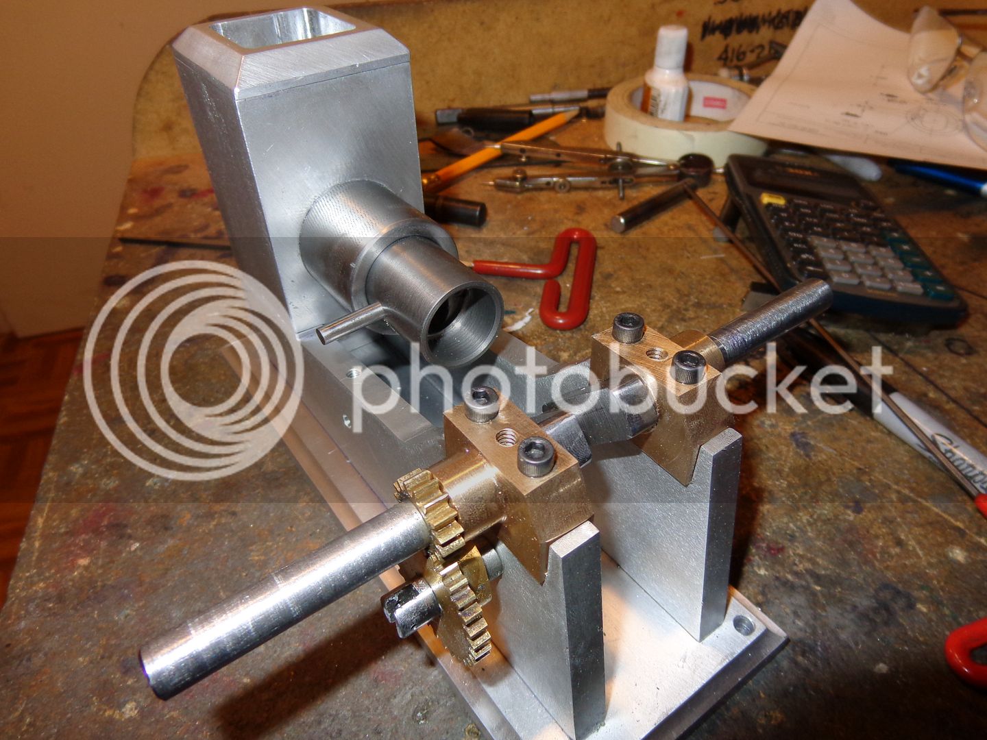
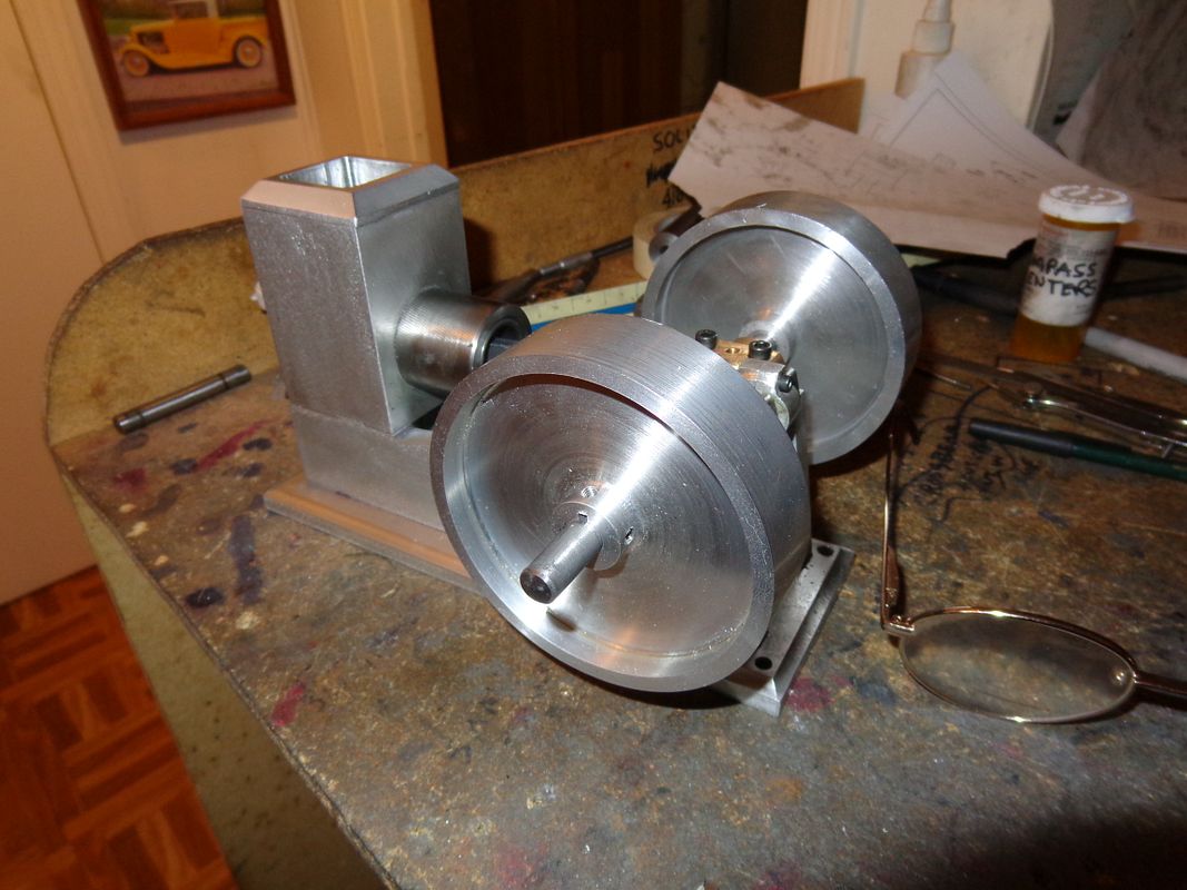
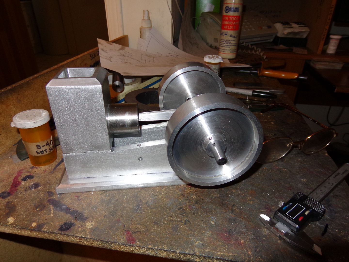
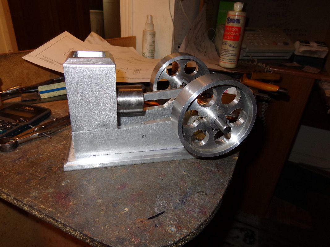
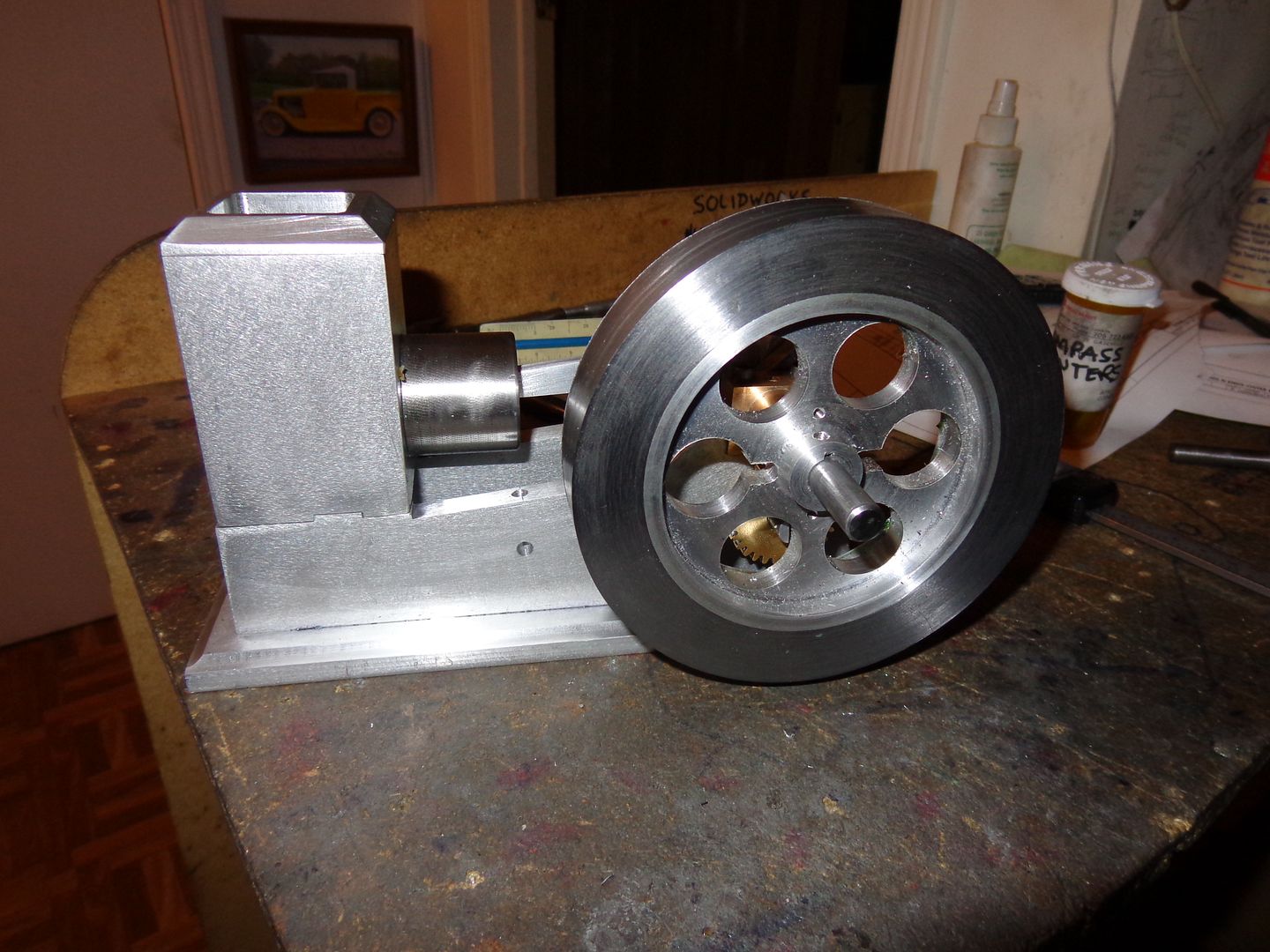
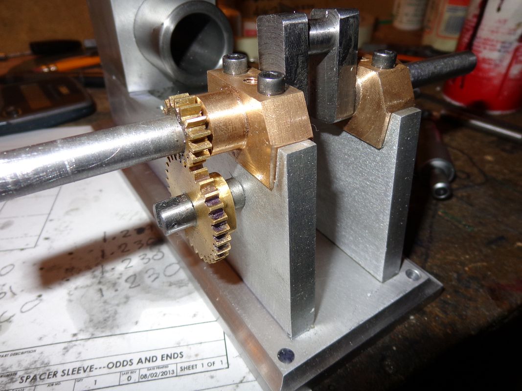
It doesn't look like much, and its not a great photograph, but two little parts were made and fitted this afternoon. The cam shaft, which passes thru the large gear and anchors in the engine sideplate, and the spacer that sets the distance from the sideplate to the side of the gear. I have to approach building these small engines the same way you would eat an elephant----one small bite at a time. If you consider ALL of the pieces, you would throw up your hands and find a different hobby. As a side note, when I built the gears and drilled a test block with the correct hole centers for a pair of dummy shafts, the gears meshed perfectly, as can be seen in the video clip at the beginning of this thread. Once I got them installed on the engine however, they wanted to bind very badly. After a lot of head scratching and measuring, I determined that "somehow" I had drilled the hole in the engine sideplate .020" too close to the crankshaft gear. Since the camshaft is locked in the sideplate with a set screw, I was able to "stretch" the hole .020" farther away from the crankshaft, and the gears mesh fine now.
Brian
CAMSHAFTANDSPACER001_zpsb0e01a0d.jpg
 
Thats some kind of nice work Brian !! Im in awe and envy of your build... Mainly envy :D !! Keep the pics comming, I learn so much from them you would not believe...Especially pics with work jiged up and ready to cut ! Bill
 
Ahhh, nothing nicer than a finely finished solid crankshaft! Truly a piece of art. Heck, Brian, looks like you'll have this thing running in a couple of days!

Chuck
 
How do you stretch a hole? Endmill?
Thats it---Used a 1/4" endmill which cuts marginally less than .25" (as tested on a scrap piece of aluminum).--First I clamped the engine to an angle plate, put a piece of 1/4" cold rolled in the milling machine chuck, then cranked things around untill it would slide into the previously reamed hole. Then I offset the table .020" in the right direction, plunged thru with the 4 flute endmill, and finished up by running a .25 reamer thru. It worked fine. The thing that saved my butt is the fact that the camshaft doesn't rotate. The cam is silver soldered to the side of the gear, which does rotate.
 
I woke up this morning feeling a bit "pistonish"---so thats how I spent my day. The other half of that piece of grey cast iron that I made the cylinder from was setting around in my shop, so I grabbed it and after about 4 or 5 hours I had a piston and I even scrounged up a bit of 3/16" cold rolled to make a piston pin from. I think this time around I may try cast iron rings. I have always used Viton O rings in the past on my I.C. engines, and they perform very well, but I would like to try using cast iron rings this time to see if there is any difference in the way the engine performs. I know of "Coles power Models" because they are mentioned in the Philip Duclos book, but if any of you guys know of a good source of cast iron rings in North America, please let me know. Don't suggest that I make them myself please. My machining abilities are not up to it yet.
PISTON-2001_zpsc4717f59.jpg
 
Accomplished a little bit today----but only a little bit. Layed out the con rod this morning, then goodwife and I took our grand daughters up to winter carnival in Orillia. Beautifull sunny winters day, watched a bunch of lunatics take the "Polar Bear Plunge" into Lake Couchiching thru a hole cut in the ice. Brrrrrr!!! When we got home I shaped the con rod cap, drilled it, tapped the main con rod body, and bolted them together. I will shape the main body of the con rod tomorrow and put in the holes for the wrist pin and crankshaft journal. Oddly, Philip Duclos doesn't call for any bushings at either end of the aluminum con rod, but then again, these are only demo engines that don't see any real working life, so probably bushings aren't needed.----Brian
CONRODLAYOUT001_zpsb886e5dd.jpg
 
Phewwwww----Had a little heart spas going there for a minute!! I got everything together, and the crankshaft wouldn't go all the way around. It hung up at just about when the piston was getting to top dead center Oh No!!! What did I do. Did I make the con rod too long? Did I make the crank throws too long??? Did I misread the drawing of the piston when i made it? Oh wait--lets shove the vernier down thru the spark plug hole and measure how far it is down to the top of the piston. 0.465"--That can't be right!! Whats going on??? Tear things all apart and sure enough---A Big glob of Loctite has oozed out when I pressed the cylinder into the water jacket and "froze' on the inside of the cylinder. With a little "scrapy, polishy, cursy" the Loctite is gone. The crankshaft goes all the way around now. I'm ahead!!! I'm going to quit for the day!!!
 
Last edited:
Today I ordered a pair of cast iron rings from Coles Power Models in Texas. This will be "breaking new ground" for me, as I have only used Viton o-rings before now.
 
Started a bunch of "flywheel foolishness" this afternoon. Both aluminum saw cut-offs were turned to 1/16" greater than finished diameter, faced on both sides to .100 greater than finished thickness, and drilled and reamed to finished size, which is .375". I have to be carefull now not to get ahead of myself, as there are a lot of steps to what I am doing, and if I get out of sequence, it can mean wasted material and starting over.
FLYWHEELFOOLISHNESS001_zps95f3e4fd.jpg
 
Nice chunk of steel pipe laying there. I assume that will be a flywheel rim? Should be nice and heavy and make for a good runner.

Chuck
 
So there we have it!!! With a lot of help from my friends, two nice flywheels, turned to size, recessed, keyseated, and set screwed. They are still 1/16" wider than the drawing calls for, so that when I mate them to the steel outer rims I can do a clean up pass on both sides. There is a tremendous lot of work in those two buggers---Its 4:35 now, and I started at 9:00 this morning. I still have to add the holes in the webs, but thats a job for another day.
FLYWHEELSONENGINE001_zpsa24d2b9c.jpg

FLYWHEELSONENGINE002_zpsf42147ce.jpg
 
The place I use for cast iron rings is at www.ringspacers.com. Dave Reed is a real agreeable gentlman and I have gotten many rings from him for models and large engines. He is in Maryland. TJ
 
I've has a very "rotary table" morning!!! My little mill runs out of power at any drill much larger than 1/2" diameter and blows its $3 glass fuse, which is a royal pain in the keester. The solution---drill all the holes thru with a 3/8" drill, then go around and plunge mill them thru with a 3/4" endmill, then go around again and plunge mill them thru again with a 7/8" endmill. This works, but it makes for a lot of cranking. Now, on to the exciting part---turning the sections of steel mechanical tubing to finished size and facing them. The maximum capacity of my lathe chuck is 5 3/8" diameter with the reversed jaws in it. The steel tubing is 5" o.d.
FLYWHEELSDRILLEDANDMOUNTED001_zpsef9651c1.jpg
 
This is how I turned the steel outer rings in the 3 jaw chuck. First operation is to set one of them against the jaws, clamp them, turn half the o.d., face the exposed face, and bore the center all except for the last 1/32" closest to the jaws to finished size. Mark the part to correspond with one of the jaws, flip it around in the chuck, set it tight against the face of the jaws, match the mark you just made up to the same jaw, machine the other half of the o.d. to match the first half, machine away the remaining exposed face untill you've eaten up that remaining 1/32 that wasn' bored. Keep on machining the face untill you are within 1/32" of finished thickness.
MACHININGFLYWHEELRINGS001_zps40b9fa97.jpg
 
Good Lord, these things look monstrous when on the engine!!! I have worked all day, hoping to get both flywheels finished and Loctited to set up overnight, but I've simply ran out of steam!!! The one on the engine is finished. The other one still needs about an hours work before it can be Loctited. After they have set up for 24 hours, I will mount them on a 3/8" arbor with a keyway so that nothing slips, and do the final finish cuts on both sides and the outer diameter. These will be very light cuts, with a newly ground tool, just to merge the aluminum and steel better visually at the parting line. The outer diameter of the steel and the outer corners need some finish work to avoid cutting fingers. The one in the picture was a perfect fit. Couldn't have machined the steel outer rim any better to fit the aluminum flywheel!!! The steel rim still on the lathe---its ended up being what I would deem a "slop assed" fit.--Its about .003 oversize. Thats what I get for not having a micrometer large enough to measure 3.625". Verniers do it to me every time. Its not really a big deal. I will take my automatic punch and punch around the o.d. of the aluminum flywheel. This will upset the metal enough that it will go from a sloppy fit to a "snug" fit, which I try to obtain, but only achieve about half the time.....
FIRSTFLYWHEELWITHRIM001_zps5d935af9.jpg
 
Last edited:
Back
Top