Philip Duclos "Odds N Ends" hit and miss engine

Home Model Engine Machinist Forum

Help Support Home Model Engine Machinist Forum:

This site may earn a commission from merchant affiliate links, including eBay, Amazon, and others.

Brian Rupnow

Design Engineer
Project of the Month Winner
Joined
May 23, 2008
Messages
14,971
Reaction score
8,254
Location
Barrie, Ontario, Canada
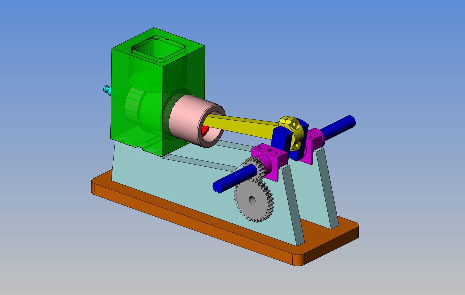
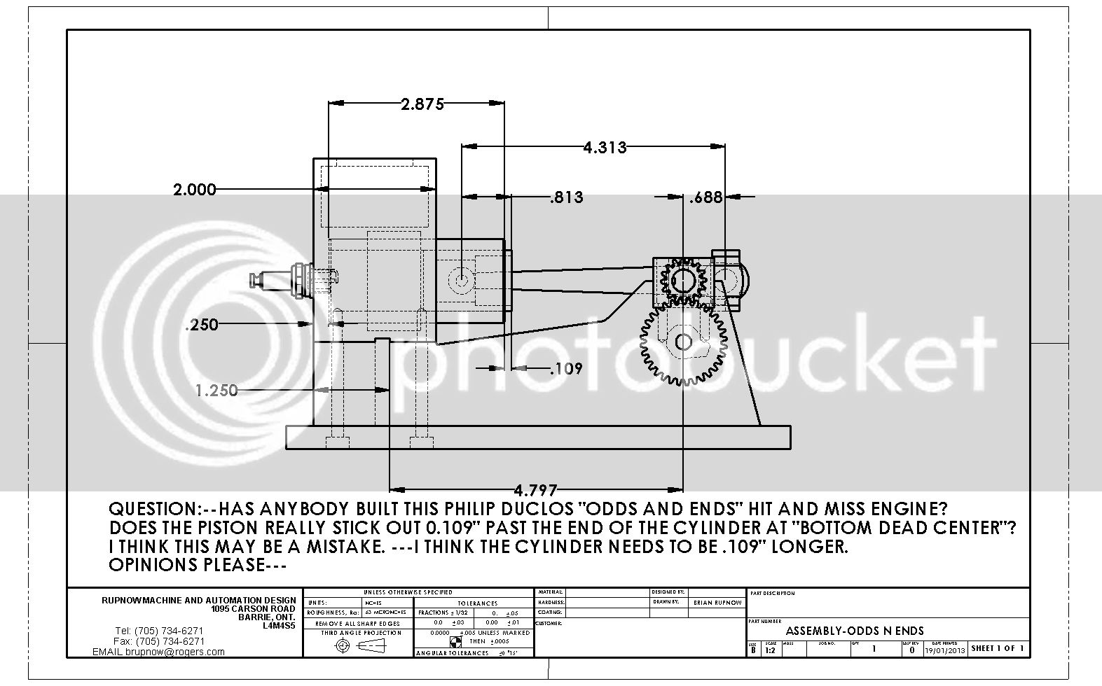
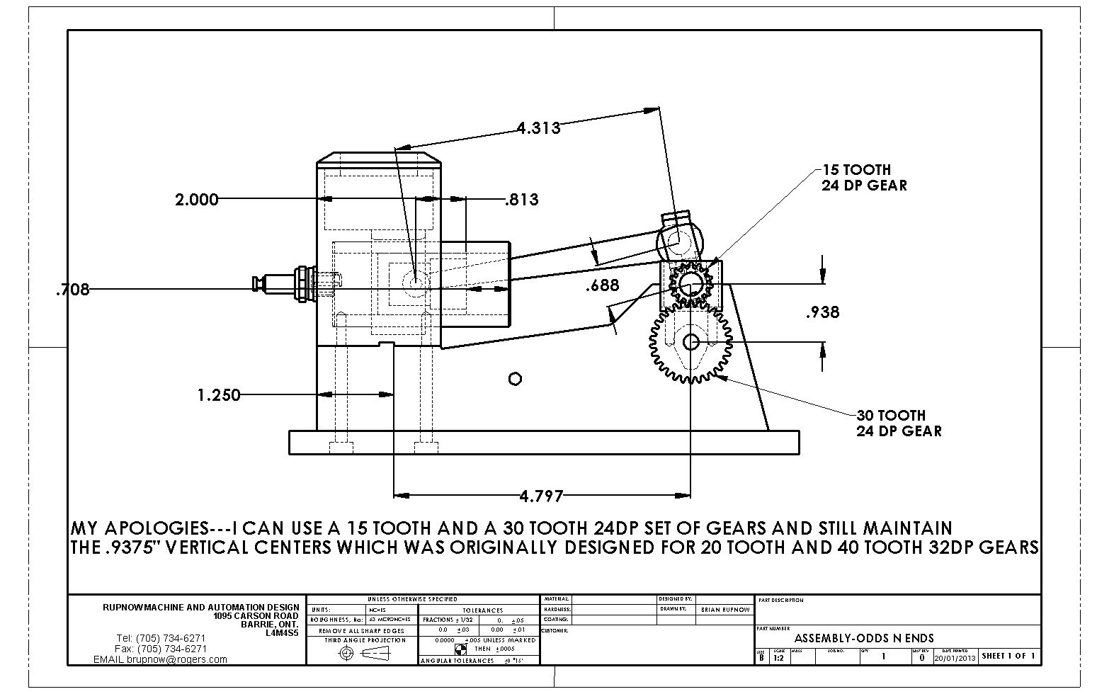
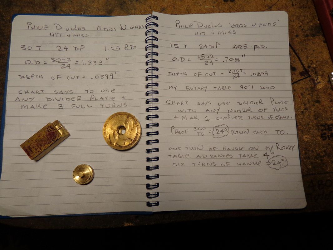
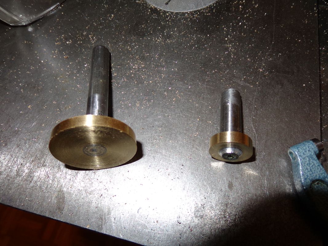
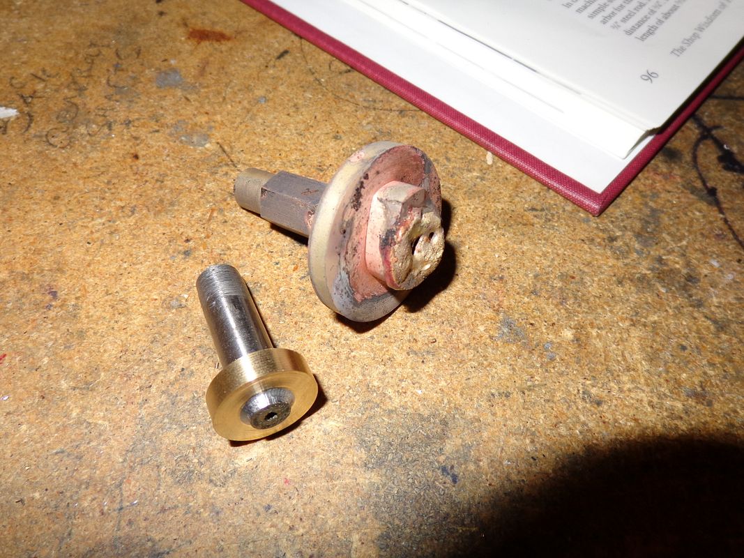
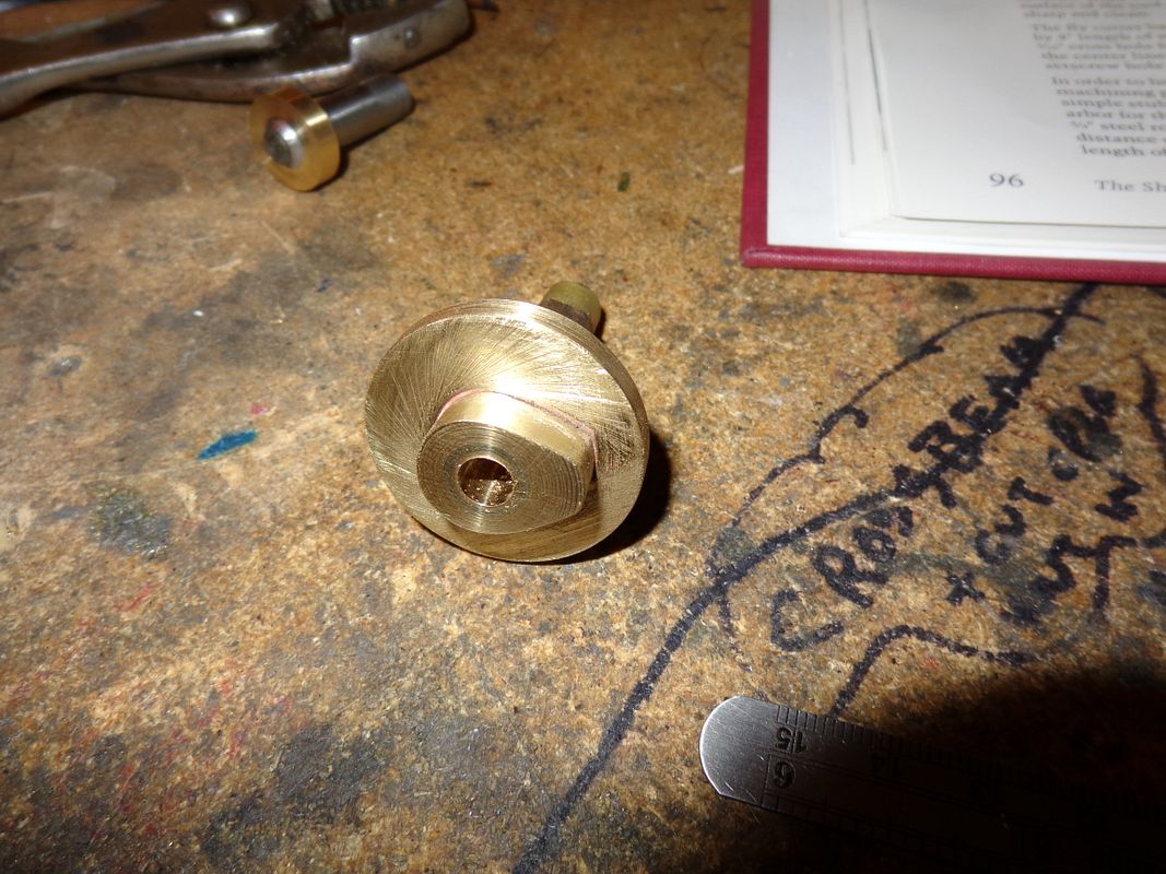
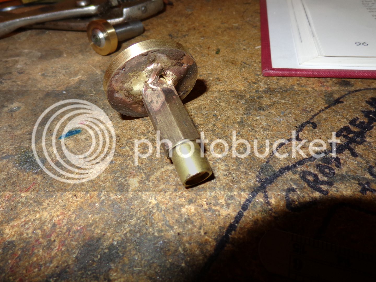
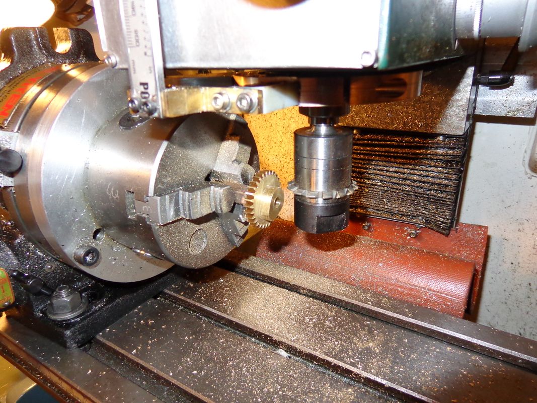
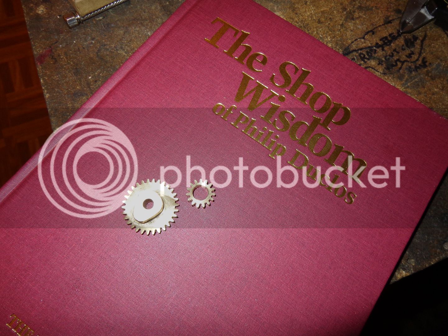
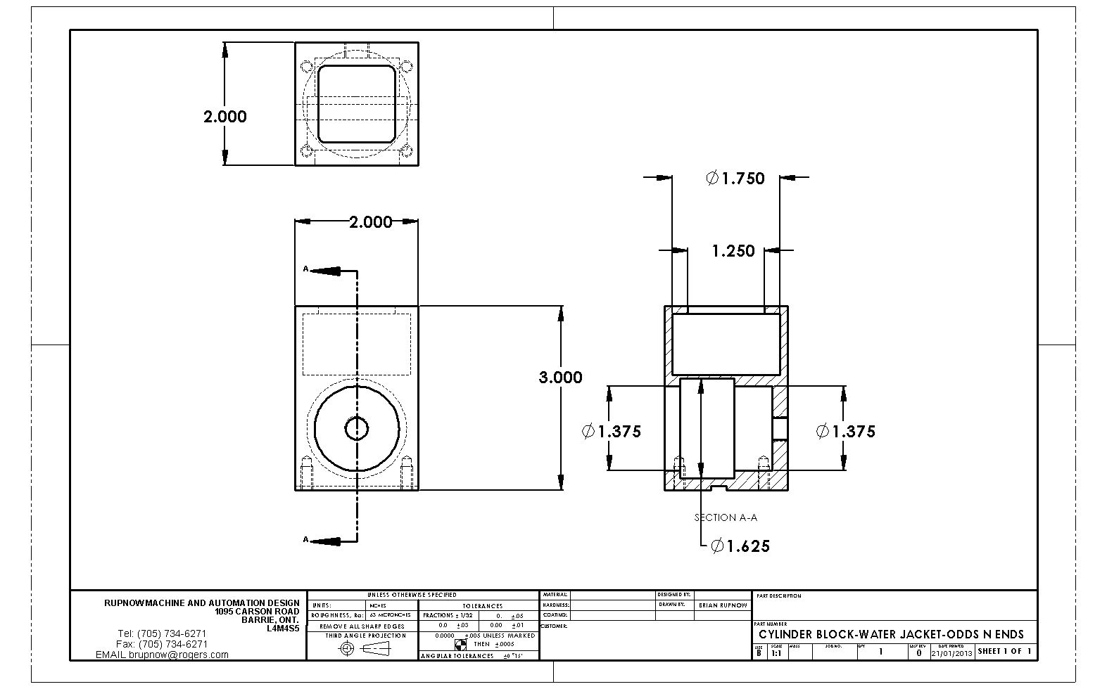
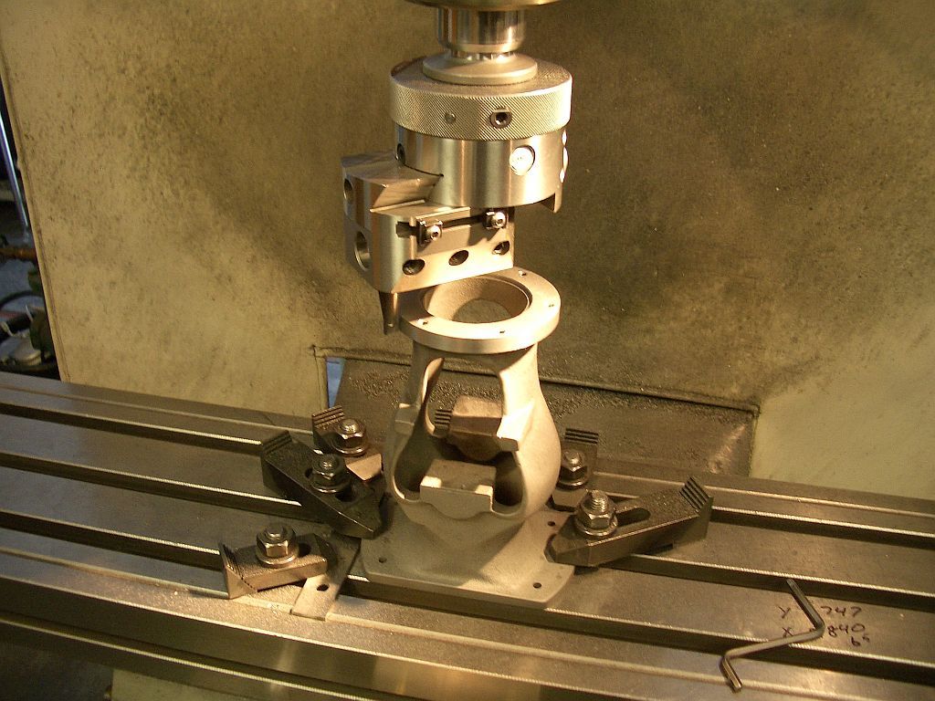
This morning I'm just setting around messing with Philip Duclos' "Odds N Ends" hit and miss engine. I have his book with the plans in it, but he calls for 32 DP timing gears while I have only 24 DP gear cutters. A little research shows me that a 16 tooth and a 32 tooth 24DP gear should work fine, and doesn't change anything except the vertical position of the cam shaft mounting hole and the rocker arm pivot hole.
ASSEMBLY-ODDSNENDS_zps9836a6da.jpg
 
The first gas engine I ever built was based on Phil's Odds'n'Ends plans. I departed radically from his design on the cylinder and the head. Actually, I guess the only thing I retained was the engine base, frame, crankshaft and overall size. It's a great little engine as are all of Phil's designs.

Chuck
 
A question for anyone who may have built this engine. Does the piston skirt REALLY stick out .109" beyond the cylinder when the piston is at bottom dead center? This doesn't seem right to me. Be aware that I have changed the left hand end of the sideplates to come out flush with the back side of the cylinder water jacket, but I haven't changed any of the mathematical relationships given in the drawings in Philip Duclos' book.---Brian
ASSEMBLY-ODDSNENDS-DRAWING_zps69d503f4.jpg
 
I may have answered my own question. I've just watched half a dozen videos on youtube of this engine running, and yes, it does seem that the piston skirt does come out of the cylinder by about .100 at bottom dead center. This seems a bit strange to me, but the engines seem to run fine, so I guess no harm is done by it.
 
Brian, This engine is on my to do list. I will be following with intrest

Dave
 
Thanks Brian for starting this thread on the odds n ends. I just finished the base and have the cylinder sleeve ready to drill out.I also have the cylinder cut out and ready to size and make it.I'm kinda new at machining and am learning as I go. I'll be looking forward to any info you have. One question if you don't have a press how do you press the sleeve in to the cylinder block? Ed
 
Ed--I have, in the past, just used a large vice. I have also (shudder) used a block of wood and a bfh. (Big Hammer). Well, truth be known, I had too much interferance fit when I built my Kerzel hit and miss. I started out squeezing the liner into place in my vice, with the liner coated with 638 Loctite, and when it stuck half way, out of sheer desperation I walked over and got my 6 pound sledgehammer and took it over to my anvil to finish the insertion. (I do not recommend this)----However I was at the point where both pieces were ruined anyways if I couldn't finish the insertion. Amazingly enough, it worked fine and has never leaked a drop of cooling water, but it was more panic stricken good luck than good management.
 
Last edited:
I was mistaken. The small gear doesn't need a keyway and setscrew. It gets pinned to the shaft with a 1/16" dowel. That means I can use a 15 and 30 tooth gear with 24 DP and still keep the 0.9375" vertical centers. I have learned something new. I didn't know that gearsets with different diametral pitches can still be configured for the same ratio and center distance. I don't know if thats true in all cases or if I just got lucky here.---Brian
ASSEMBLY-ODDSNENDS-DRAWING_zps4caeac73.jpg
 
I haven't cut any gears since I built my Steam Donky Winch over a year ago. I just got out all my paperwork and my gear cutters out for a full review. I found a few bits and bobs of brass in my brass drawer and came up with enough material to make two gears and the cam. In the original plans, the cam is machined right on the face of the larger 30 tooth gear, however I will have to solder the cam to the large gear. Here is a picture of the bits of brass I came up with, and the calculations I just made to set up my mill and rotary table, and to turn the blanks in preperation for cutting the gears. If anyone has questions, go ahead and ask.
GEARCALCULATIONS001_zps8d86a08c.jpg
 
Thanks Brian for starting this thread on the odds n ends. I just finished the base and have the cylinder sleeve ready to drill out.I also have the cylinder cut out and ready to size and make it.I'm kinda new at machining and am learning as I go. I'll be looking forward to any info you have. One question if you don't have a press how do you press the sleeve in to the cylinder block? Ed

Another method is to use a threaded rod, probably at least 1/2" for this sized project. Thread the rod through the cylinder and the liner with large washers on each end. Best if the washers are turned with a shoulder so they keep the rod centered in the work pieces. Then us a nut on each end and tighten to pull the sleeve through the cylinder. Oil the rod and nuts to minimize friction.

Chuck
 
This first picture shows the two gear blanks turned to the correct outer diameter and thickness. To do this I first drilled and reamed the center holes by mounting the pieces in my lathes 3 jaw chuck and using drills and reamers mounted in the tailstock chuck to get the 3/8" center holes in them. I then Loctited them onto short lengths of 3/8" cold rolled shaft so I could hold the cold rolled in my lathe chuck and finish the o.d. and thickness of the parts. The 3/8" bore will be the finished bore in the small gear. The large gear will get the cam and a 3/8" diameter piece of brass silver soldered to it for "further processing".
TIMINGGEARSSOLDERED002_zps1a9003f3.jpg
 
This is the large gear blank with the cam and a piece of 7/16" hex brass turned to 3/8" and all silver soldered together. Messy looking brute isn't it!!!
TIMINGGEARSSOLDERED003_zpse371e1c3.jpg
 
This is the large gear with the cam soldered to it "cleaned up" on the face side. The back side is still uglier than sin, but I will hang onto that hex shank to cut the gear teeth, then cut the shank off and clean the back side up as well. Both the gear blank and the cam had a .075 x 45 degree chamfer around the bore to hold a good solid ring of silver solder after everthing is cleaned up.
solderedcamcleanedup001_zps180fe724.jpg

solderedcamcleanedup002_zpsd81530d1.jpg
 
Last edited:
So, after almost a whole day fiddle-fartin around, I have a set of gears and a cam. Its a good thing I don't charge myself by the hour---I couldn't afford this!!! Seriously, I don't do enough of this to really be comfortable with it. Its not like learning from scratch each time I do it, but it certainly makes me refer to reference notes I have made in the past when making gears. That book that I showed in an earlier post with my gear calculations in it is a real treasure. I have a new note to put in it this time.---Use longer stub arbors to keep the gear blank farther away from the rotary table chuck, or there won't be clearance for the gear cutter and the chuck jaws. I had to scab extensions onto both stub arbors today to achieve this clearance.---We learn, we learn!!!
GEARSFINISHED001_zps4781a46b.jpg

GEARSFINISHED003_zpsaaac0215.jpg
 
Looks great Brian. I cut some gears several years ago. You are right if you don't do it a lot it takes a while to get back up to speed.

Dave
 
Yes, I do write notes to myself!! At least on something like cutting gears, which I don't do very often. Its amazing how much this helps the next time I have to do this.
timinggearsmeshing002_zpsfdcf0077.jpg
 
And last but not least, the gears mesh properly at the correct center distance. I notice that I have inadvertantly rounded off the outer corner of the cam during my clean up filing and sanding. That won't effect the way it works though, as the cam follower rides on the portion of cam which is right up tight to the gear face.
 
I just learned something new this afternoon. I always thought that anything that could be bored on the lathe could also be bored with a boring head on the mill. I'm pretty sure I was wrong. Take a look at the bores in this water jacket. Neither could be made with a boring head on the mill. Why?? Because to do the larger internal bores, you have to be able to advance the radius of the tool while the tool or the part is turning under power. That is easily done with a boring bar in the lathe. With the lathe running and the cutting tool on the boring bar part way into the smaller finished bore, you can back out the cross slide and increase the tool radius. You can't do that with a boring head. Son of a gun, I like it when I discover something new!!!
CYLINDERBLOCK-WATERJACKET-ODDSNENDS_zps30bb0e51.jpg
 
Hi Brian

I depends on the boring head; I have two of them that will allow the cutter to advance while it is turning. Here is a picture of my larger one in use as a fixed diameter on this setup. Holding the knurled ring at the top causes the tool to move out a little bit each revolution. This one has three feed rates.

Body_007.jpg


They work great for facing; I have machined hundreds of air cooled VW heads over the years with this head.

Dave
 
Back
Top