I have spent enough hours this summer frittering away my shop hours on flame-sucker engines, Sterling engines, and clutches. My plan for the coming winter is to design and build a side-shaft hit and miss engine from bar-stock. I have built enough engines now that the only really "new" thing will be the gears that run the side-shaft, and the governor that controls the "hit and miss" action. I hope to purchase gears, bearings, etcetera from commercial dealers so that when I eventually have a running engine, other people will be able to buy the same parts from the same dealers. The engine will be water cooled, with a horizontal cylinder, 1" bore and 1 3/8" stroke. The intake will be an atmospheric valve with no cam to actuate it. Probably about 90% of this engine will be similar to parts I have machined before on the Kerzel and the "Odds and Ends" engine from Philip Duclos. I don't plan on using a Viton o-ring for a piston ring, because although they create a wonderful seal on the piston, I think they have enough residual "drag" that they prevent the engine from having very many "miss" cycles. In fact, I hope to use no rings at all, but will lap the piston into the cylinder for an air tight fit like I did on my marine engine. I hope to aim for a compression ratio of about 4.5:1. Ignition will be the Dodge points and condenser that I have used on all of my other i.c. engines. Both piston and cylinder will be grey cast iron, and the flywheels (2-of) will be 6" diameter. I am still doing research on the cam and governors, and haven't fully decided what I will use. Whatever it is will no doubt be a copy of someone else's successful design.---Brian Rupnow
You are using an out of date browser. It may not display this or other websites correctly.
You should upgrade or use an alternative browser.
You should upgrade or use an alternative browser.
Design and build side-shaft hit and miss engine from bar stock
- Thread starter Brian Rupnow
- Start date

Help Support Home Model Engine Machinist Forum:
This site may earn a commission from merchant affiliate
links, including eBay, Amazon, and others.
Hi Brian,
I will be watching, good luck with it.
Cheers
Andrew
I will be watching, good luck with it.
Cheers
Andrew
George Britnel showed me pictures of how the governor works on a "domestic stovepipe" hit and miss engine, which he has recreated on a very small "tiny" hit and miss engine--It took me a while to get my head around this, but I think I have it. Things are not modelled to any particular scale, but that's okay for "show and tell". Red indicates the flywheel. The light blue indicates the round part which fits over the flywheel with about half a thou radial clearance. The slot milled in the center of that light blue part is long enough to give the offset required. The light blue part has a rod extending from one side of it thru the pink counterweight and thru the spring and thru the light brown bracket. The pink counterweight is firmly attached to the rod. The rod goes thru the light brown bracket with a clearance fit.--Normally, at zero rpm, the spring holds the light blue part centered on the crankshaft. As the rpm increases centrifugal force makes the pink weight want to move away from center, and as it does it pulls the blue part away from center until it is limited by the other end of the slot coming up against the crankshaft. The dark blue eccentric strap and rod which runs out to the bell crank doesn't move at zero rpm. as nothing is eccentric. As rpm's climb and the light blue part becomes more and more eccentric to the crankshaft, the eccentric strap follows it and the rod extending from the eccentric strap moves in a linear motion to operate the bell crank at the far end to lock out the exhaust valve.----Brian
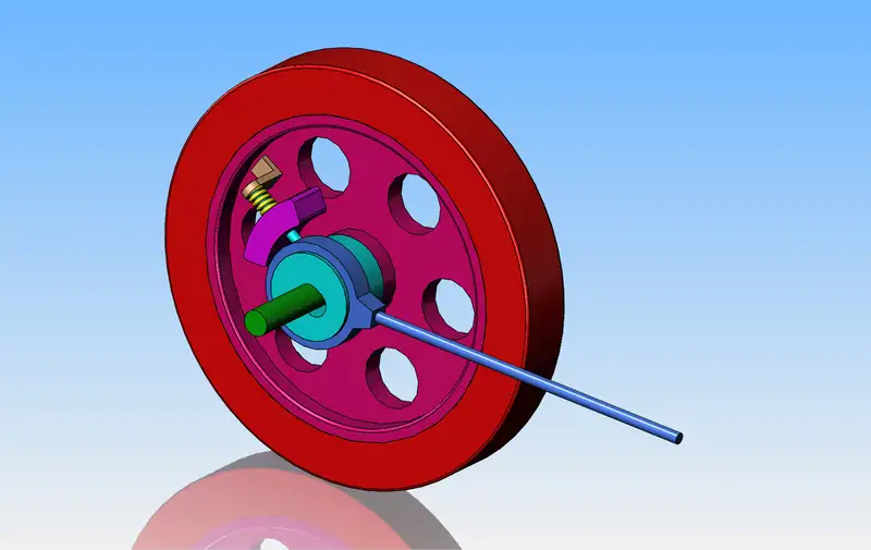

Something about the previous explanation troubles me. Obviously, the counterweight and the light blue part it is attached to have to rotate with the flywheel in order for centrifugal force to pull the light blue part off center. At zero rpm when the light blue part is centered on the crankshaft, the dark blue eccentric strap and attached rod isn't going to move.---But--As soon as the light blue part is pulled off center the eccentric strap is going to follow it, and the rod attached to that eccentric strap is going to move back and forth. Somehow I think that the rod attached to the eccentric strap shouldn't be bopping back and forth to do it's job properly. What am I doing wrong?
Okay--George came thru with an explanation---"You're correct about the strap and lock-out rod moving back and forth. The trick of this is when the rod moves forward it pushes the lock-out lever into contact with the rocker arm but the lock out lever isn't fixed to the lock out rod rather the lock-out rod slides through the lock-out lever so it only pushed it in one direction. There is a stop on the lock-out shaft that moves the lock-out lever. If you look at picture 9422 you will see that the end of the lock-out rod is threaded and has 2 nuts on it. The one nut is for adjusting how far the lock-out lever moves and the other is the lock nut. The travel of the eccentric has to be greater than the required movement for the lock-out lever so that's where the adjusting nuts come into play."
gbritnell.
gbritnell.
I have checked out the two part numbers for the helical gears from "Martin" in USA that are on the engine being built by Craig DeShong. The 12 tooth helical gear is part #BS1612-2 and sells for $38 USA. The 24 tooth helical gear is part #BS1624-2 and sells for $63 USA. That comes out at $101 American money and $133 Canadian money. Ouch!!! Maybe it's a good thing that I'm rich instead of good looking.
And as it unwinds--the part numbers I got from Craig DeShong are for straight tooth bevel gears, not helical gears. I think he may have mistakenly given me part numbers for the governor gears on his engine, not the helical gears. The prices I gave in an earlier post were for straight tooth bevel gears, not helical gears.--I will still probably have to buy those gears, as I do intend to have a governor on the new engine I design. DeBolt has a set of helical gears with the right ratio and a reasonable size, but I can't reach anybody at DeBolt.--I sent DeBolt 3 emails yesterday and they were all answered with an email from Paul at DeBolt with no message nor attachment. I called them this morning and left a message, but I can't do much now until I hear back from them. I don't even want to start the design of the engine till I get these gears figured out.
terryp
Active Member
Wow Brian, Hit and Miss engines have always fascinated me having collected and restored a few. The sideshaft engines are especially attractive because of all the moving and wiggling parts. I am finishing up my second model engine now, working toward I.C. someday. Will be watching with interest and envy. Terry from TexasAnd as it unwinds--the part numbers I got from Craig DeShong are for straight tooth bevel gears, not helical gears. I think he may have mistakenly given me part numbers for the governor gears on his engine, not the helical gears. The prices I gave in an earlier post were for straight tooth bevel gears, not helical gears.--I will still probably have to buy those gears, as I do intend to have a governor on the new engine I design. DeBolt has a set of helical gears with the right ratio and a reasonable size, but I can't reach anybody at DeBolt.--I sent DeBolt 3 emails yesterday and they were all answered with an email from Paul at DeBolt with no message nor attachment. I called them this morning and left a message, but I can't do much now until I hear back from them. I don't even want to start the design of the engine till I get these gears figured out.
Sent from my Moto E (4) using Model Engines mobile app
terryp
Active Member
We're good!!! I just got a phone call from Paul Debolt at Debolt Machine and he is still in business and plans on staying in business. I ordered the helical gears from him, and I also ordered the "Martin" straight tooth bevel gears that will run the governor from the Canadian company I was dealing with. I won't do anymore design work until I have these gears in my hands. --Brian
terryp
Active Member
Almost done, over a year in the making. Building experience toward more complex I.C. engines. Terry


Sent from my Moto E (4) using Model Engines mobile app


Sent from my Moto E (4) using Model Engines mobile app
I'll be watching this one, too.
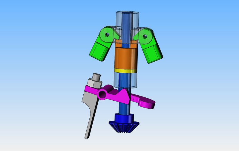
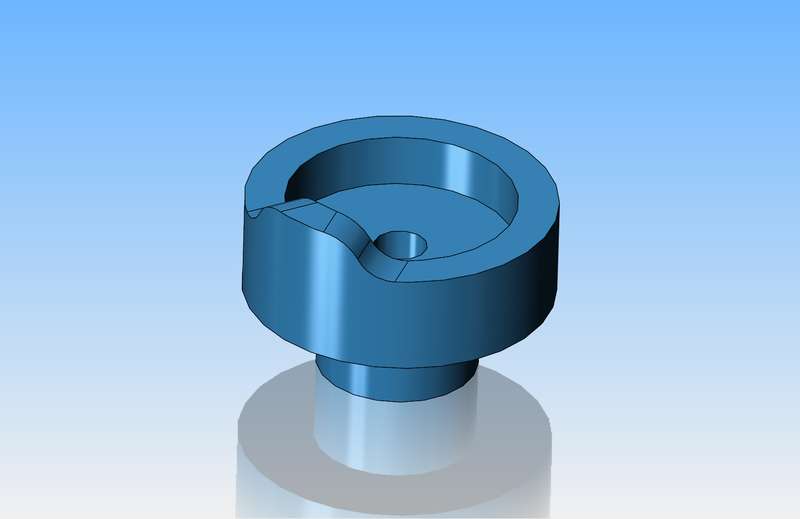
I bought the two bevel gears because I like the style of governor used on the Bob Herder side shaft engine currently being built by Craig DeShong. I want to marry that style of governor to the circular cam disc as used on the Silver Angel engine. This will let my cylinder head be much closer to a "conventional" style of cylinder head rather than having to assemble two piece valves inside the cylinder head as Craig has done. I haven't put a lot of thought into just how I will do that yet, but I think it will be possible.
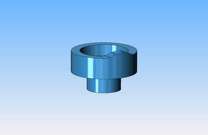


Brian, what program do you model in?
I do my modeling in Rhino and something like that second pic (cam?) would require making an inverse shape to "Boolean" with a flat cylinder. The profile might need to be done freehand.
I do my modeling in Rhino and something like that second pic (cam?) would require making an inverse shape to "Boolean" with a flat cylinder. The profile might need to be done freehand.
Bob--I work in Solidworks, and I am aware that the image of the cam is not technically correct. I just did a quick model so people would be aware of what type of cam I was talking about.---Brian

Last edited:
You're a mile ahead of me, Brian. Which isn't surprising. I didn't know or even think the cam was wrong.
My version of Rhino is now obsolete; they came out with a new one a few months ago. I either keep using it or go on the search for something else - probably Fusion 360.
There are lots of reasons to go with Fusion.
My version of Rhino is now obsolete; they came out with a new one a few months ago. I either keep using it or go on the search for something else - probably Fusion 360.
There are lots of reasons to go with Fusion.
I am going to try and use a CM10 sparkplug on this engine because they are available at any autoparts store. Anything smaller is generally more expensive and can only be ordered from specialty suppliers. With a 1" cylinder, I'm sure I can make it fit, because I have three or four other 1" bore engines, and there is just enough room in the cylinder head for two 3/8" diameter valve heads and the 10 mm sparkplug.
marvin hedberg
Active Member
if you need a smaller plug, these are available http://sparkplugs.morrisonandmarvin.com/index.phpI am going to try and use a CM10 sparkplug on this engine because they are available at any autoparts store. Anything smaller is generally more expensive and can only be ordered from specialty suppliers. With a 1" cylinder, I'm sure I can make it fit, because I have three or four other 1" bore engines, and there is just enough room in the cylinder head for two 3/8" diameter valve heads and the 10 mm sparkplug.
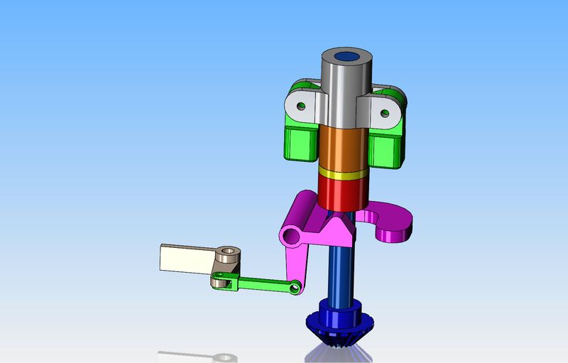
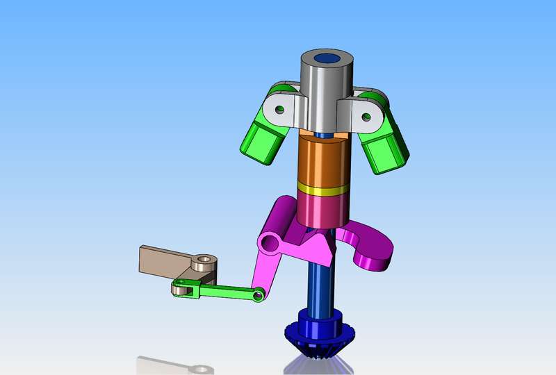
After watching many more videos of full size "Domestic Stovepipe" engines, thigs are beginning to come clearer. The Domestic Stovepipe engines have a circular disc cam, similar to the cam on the Silver Angel. It has a really nice governor set-up which rides on one flywheel and connects to the exhaust valve lockout lever with a long pushrod. The beauty of this style of governor is that you don't have to shell out any cash for miter gears to run the governor shaft. On the Bob Herder hit and miss engine like Craig DeShong is building, the sideshaft, running at 1/2 of the crankshaft speed has a conventional shaped cam to run the exhaust valve. The problem with that is that the pivot point of the rocker arm is rotated 90 degrees from "normal", which leads to a really strange cylinder head into which the valves must be assembled in pieces.---and--It costs an extra hundred dollars for bevel bears to run the governor shaft. However--It looks really neat, with the exposed governor setting up on the side of the engine.
So without worrying about scale too much, we want a model of the Bob Herder hit and miss governor pivoting an exhaust valve lockout mechanism similar to that used on the Domestic Stovepipe engine. This will do it. That green colored link will have to have a spherical rod end on the right hand end to let things move without binding.


Similar threads
- Replies
- 148
- Views
- 24K
- Replies
- 5
- Views
- 2K


