Well Idahoan---Thats impressive!!! I didn't know there was such a tool. It looks to be a tool that would be beyond reach dollarwise for a hobby machinist. Thank you for showing me.----Brian
Hello Brian,
Yes I built this engine back in the eighties and it run great. The piston does extend out like you say but does no harm as it has a fairly long skirt. I modified my engine by making it overhead valve. and the valve gear was placed on the opposite side. It was a sturdy little engine started and run well. I ran short of money back in the nineties and sold it. Have since made another which is basically free lance called "MODERNA" a hit and miss but with more modern lines.
jowen
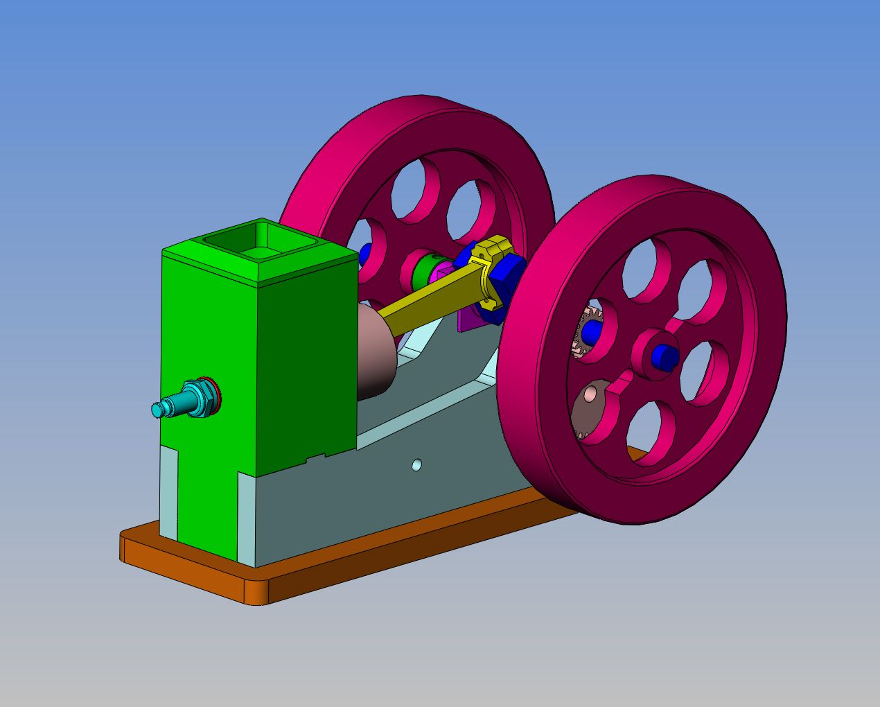
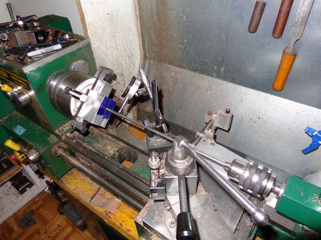
The original plan for this engine used a pair of angles for the side plates, and perched the water jacket up on top of them, leaving a gap between the underside of the waterjacket and the base. The water jacket also hung out past the back of the sideplates. I didn't fancy the overall look of this, so have decided to make the sideplates from 3/8" plate and to "profile" the water jacket to extend down between them to the baseplate. Of course this leaves me with a water jacket which requires a lot of carving and milling on it. I have also decided to make the top of the water jacket from a seperate piece. I have finished the profiling of the water jacket, and am about to set it up in the 4 jaw chuck in my lathe to bore the hole for the cast iron cylinder. I hate using the 4 jaw chuck worse than snakes, but sometimes ya gotta do what ya gotta do. I will post a picture when everything is set up in the 4 jaw. I went over to BusyBee this morning and bought two new boring bars which hold a 1/4" square HSS bit, so this will be something relatively new for me.
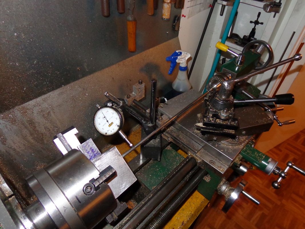
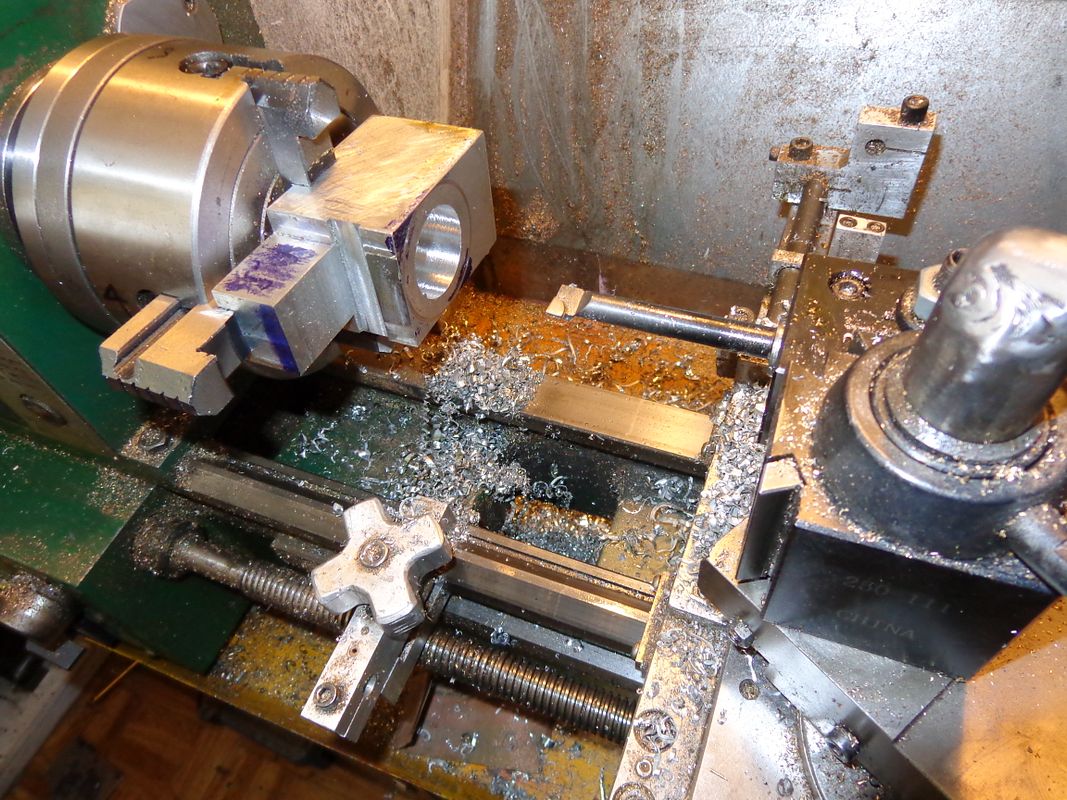
After 20 minutes of tightning and loosening chuck screws, (Thats the part I hate about 4 jaw work) I finally got down to .002" movement of the needle on the dial indicator. I couldn't get any closer than that, so decided to quit while I was ahead and tighten everything up. A couple of good raps on the face of the part with my dead blow hammer to seat the part firmly against the chuck jaws, and its ready to be bored. May the force be with me----
Brian I'm at the same spot as you are. I drilled the hole in the block of steel yesterday up to 1in.now I need to bore it out. I have a home made boring bar. We'll see if it works. I'll try to take some pictures this afternoon and see if I can figure out how to attach them. The largest drill I have is a 1in so have some boring to do. Ed
... it is quite common for the original full scale hit 'n miss engines to have the piston skirt come out of the cylinder a bit. It's been a while since i have run them but I'm pretty sure both my 1-1/2 HP Economy and my 7 HP Galloway do that.
I may have answered my own question. I've just watched half a dozen videos on youtube of this engine running, and yes, it does seem that the piston skirt does come out of the cylinder by about .100 at bottom dead center. This seems a bit strange to me, but the engines seem to run fine, so I guess no harm is done by it.
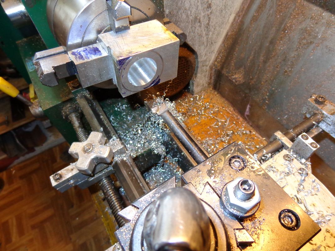
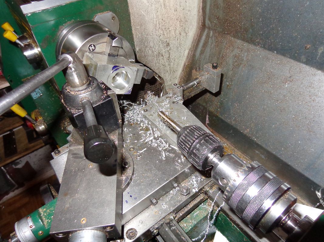
Well, this appears to be as good as it gets with my Chinese brazed carbide boring bars. I first used a center drill in the tailstock chuck to get things started. Then I switched to a 0.341" drill (which is about right for a 10MM x 1 pitch sparkplug thead) and drilled all the way thru the aluminum block. Then I used up to a 3/4" drill in steps, taking great caution not to send the tip of the drill into the block amy more than 1.75". Last step was to send a 3/4" 4 flute endmill down the hole to ensure a totally flat bottom in the hole. I set up my lathe stops to ensure that I wouldn't go deeper than 1.75". Then with my brazed carbide tool I started taking .005" radial cuts at 300 rpm. This worked but produced a very heavy chatter, so I went to my slowest lathe speed, 115 Rpm. after MANY in and outs with the boring tool, I closed in on my final desired diameter of 1.375". after that, I ran the boring tool in and out an absolutely amazing number of times untill it cut "spring cutting"---That is to say, removing material even though i hadn't advanced the tool, caused by "springiness" in the shank of the carbide tipped boring tool. when i finally got to the point where it was no longer removing material, my hole mikes out a 1.379" diameter. This is not a big deal, as i will be turning the outer diameter of the cast iron cylinder to fit the bore. Now I get to set up my new boring bar with the inserted 1/4" hss cutting bit to open up the recess around the 1 3/8" hole to 1 5/8" which provides circulation of water around the cylinder. This is the bore I decided couldn't be done on the milling machine. (At least not with my boring head.)
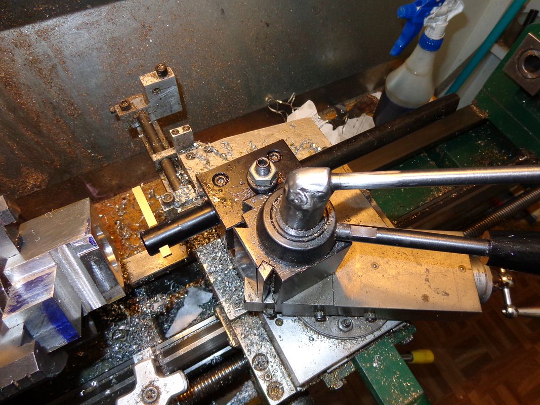
Now, this is a BORING BAR!!! It is 3/4" dia. x 12" long with a square hole through one end and a 45 degree hole thru the far end for a 1/4" square hss. cutting tool. Okay, I know i have to cut the 1/4" cutting tool much shorter. What I don't know, is whether to try cutting/boring with the full width of the 1/4" face. It seems to me that would chatter very badly. My plan at the moment is to grind the first 1/4" of length down to only 1/8" wide, and do the same to the opposite end of the tool, but on the opposite side. This will effectively give me a "right hand tool" and a "left hand tool". I will go to the extreme depth of the 1 5/8" coolant passage and do a plunge cut to the full 1 5/8" diameter. I will then switch ends on the cutting tool, move to the other end of the 1 5/8" coolant passage and do another full depth plunge cut. Remember now, this plunge cut will only be 1/8" deep. Then i can back my tool out and take lighter cuts back and forth between these two annular rings untill the entire coolant ring area is opened out to 1 5/8" diameter. Does that sound about right??
Jeez Ed--You're way out ahead of me!!! I had to drive to a customers this afternoon, and got thinking on the way. I don't need to grind right and left hand ends on my cutting tool. Since I'n not boring up tight against an adjacent face, I only need to reduce the width at one end to 1/8".
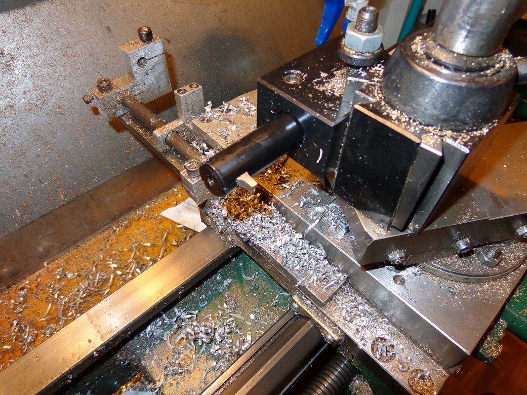
I had to drive to a customers this afternoon, and got thinking on the way. I don't need to grind right and left hand ends on my cutting tool. Since I'n not boring up tight against an adjacent face, I only need to reduce the width at one end to 1/8". This is what I ended up with. I did have really sharp corners on each side of the cutting edge, and was wondering about creating stress risers in the part I was machining. I took a look at picture #7 in Philip Duclos' book and seen that he had a fairly good rad on the tool he shows, so I dismounted the tool after this picture was taken and stoned a small radius on each sharp corner.
Well, that was interesting. In fact---Ah Hell, I'll come right out and say it---It was kinda SCARY!!! However, evrything worked just like the machining books said it was supposed to!! I had set my carriage stops both front and rear so that I didn't have to count turns, I just ran the carriage back and forth between the stops. I could feel a bit of chatter, so I worked with my rpm at 115 and took about .003" to .004" radial cut. I kept squirting oil in periodically, and stopped the lathe a couple of times to pull out chips from the hole with my needle nosed pliers. when I was all finished boring, I put my M10 sparkplug tap in my small chuck, held in the larger tailstock chuck, and manually turned the headstock chuck with the tailstock not locked down. This let the tap pull itself thru and remain perfectly centered. Everything is removed from the lathe now and wiped clean, and I must say it looks awfully good. I haven't used this type of boring bar and tool before, but it all worked as adverised with no disasters.
Now I will ask an opinion. The waterjacket I have been working on also gets a large bore in the top to contain water, and a thru hole to let the water circulate around the cylinder. In Philip duclos' book, he pressed the cast iron cylinder liner into place before putting these other holes in the waterjacket. I would find it much more convenient to put all the holes in the waterjacket first, and press the cylinder into place (with lots of Loctite) as a last operation. Would there be any good reason not to do it the way I prefer?---Brian
Brian Thanks for all the help and directions you are giving me. I could not have gotten as far as I have with out your directions.I will be following your build. Thanks for the pictures they realy help. Ed
I have been warned by other, more experienced heads than mine, to press the cast iron cylinder into place, using lots of Loctite and let it set up 24 hours, before I bore out the water jacket area.
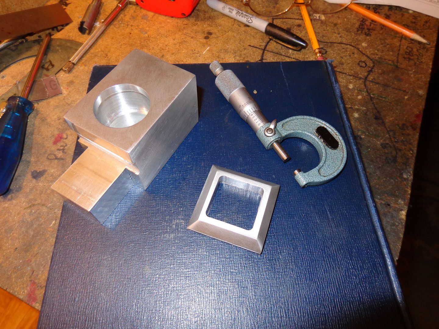
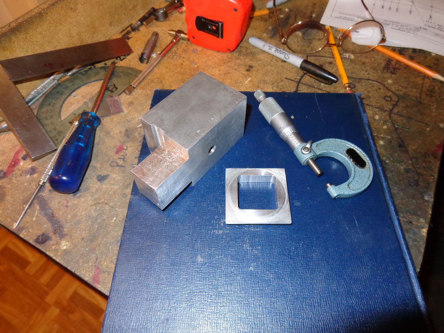
I found a little time this afternoon (actually quite a bit of time) and made the top for the waterjacket. Since I opted to have a "tail" on my waterjacket to fill up the gap between the sideplates, there was no way I could fit the waterjacket into my 4 jaw on the lathe to do the stepped bore for the water container. Not a big problem. I'll do the bore for the water container part of the water jacket on my mill, and Loctite the top on as a seperate piece. Since I had the 4 jaw chuck on my lathe anyways, I decided the top should have a 3/16" long x 1.75" diameter projection on it to fit inside the bored hole--all the more for the Loctite to hold onto.
So, Brian, I'm guessing you are committed to building this engine now???
Nice work, as usual. One question, before you turned the projection on the water jacket top, were you planning to just Loctite two flat surfaces together? Will that work? I thought Loctite only worked with one piece inside another...
Its a trick, Chuck. That was my plan all along. I wouldn't trust Loctite to stick 2 flat surfaces together. Now watch--100 people will jump in and say they use it that way all the time and it works for them!!!
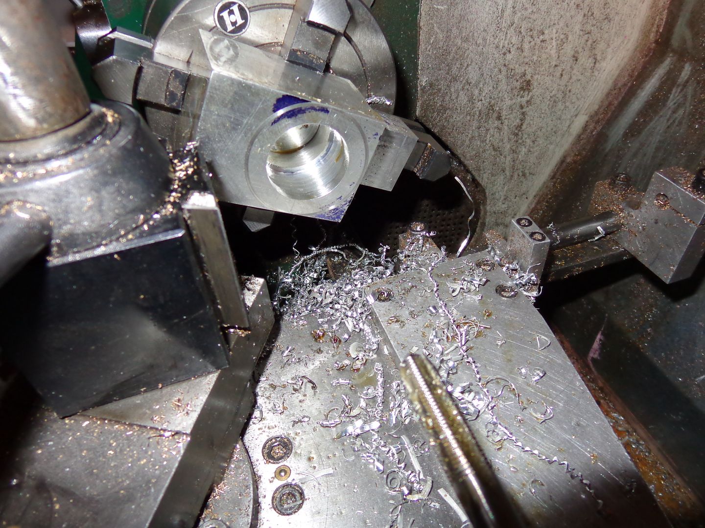
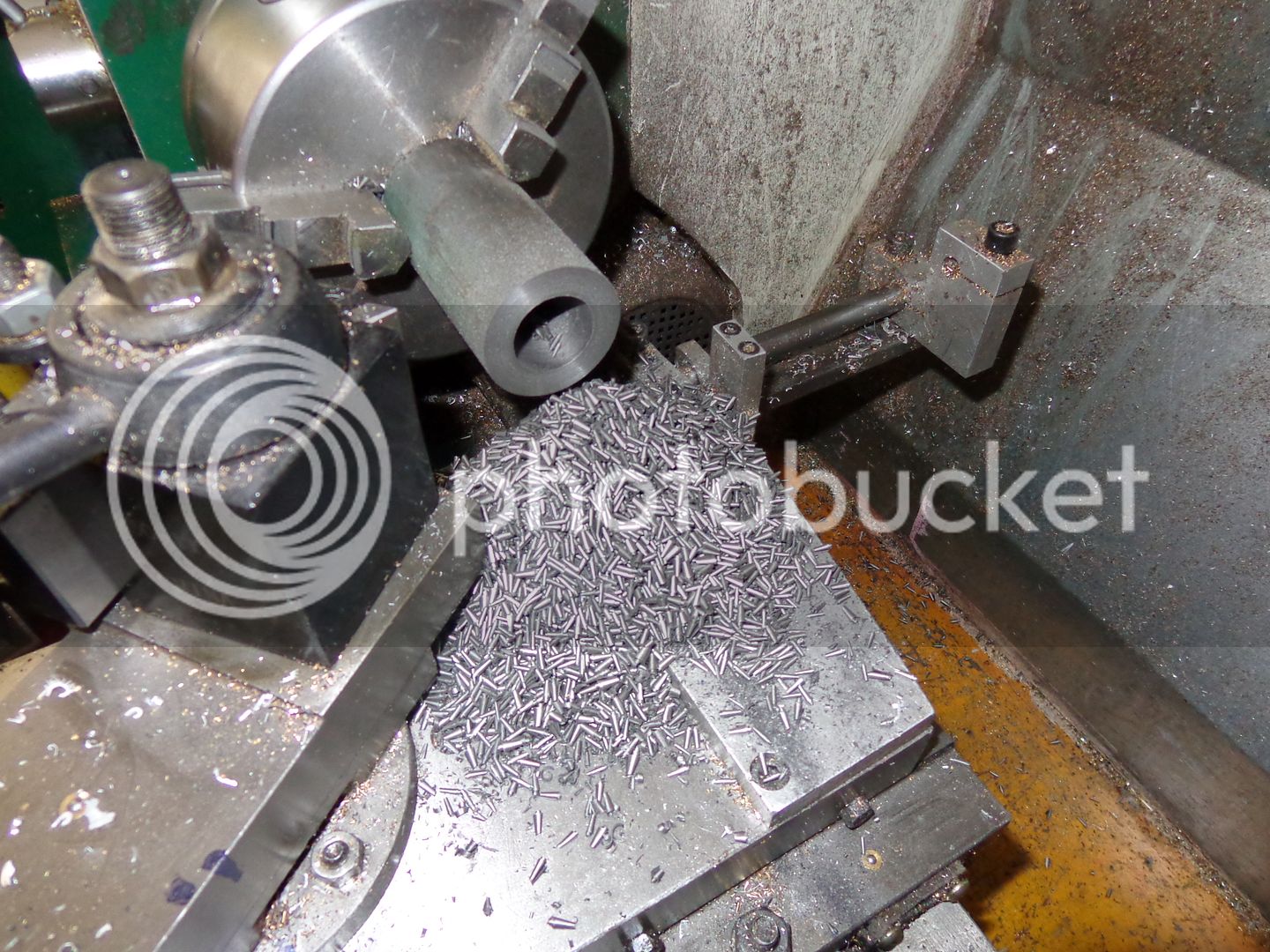
And here we have---"Swarf Mountain"!! I tried to buy grey cast iron that had a hole cored thru it similar to heavy wall pipe, but all my supplier had was 1.5" dia. solid round bar. This, as shown, has a 15/16" hole drilled thru it. I step drilled with 3/8", 1/2", 5/8" and then jumped to 15/16". Now I will mount it on a 15/16" arbor and turn the outside to what I hope/hope/hope is a medium press fit into the aluminum water jacket. Before it gets pressed into the water jacket, I will remove the arbor, hold the outer finished diameter in my chuck, and ream the bore to its finished 1.00" size.