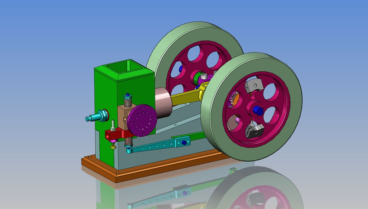
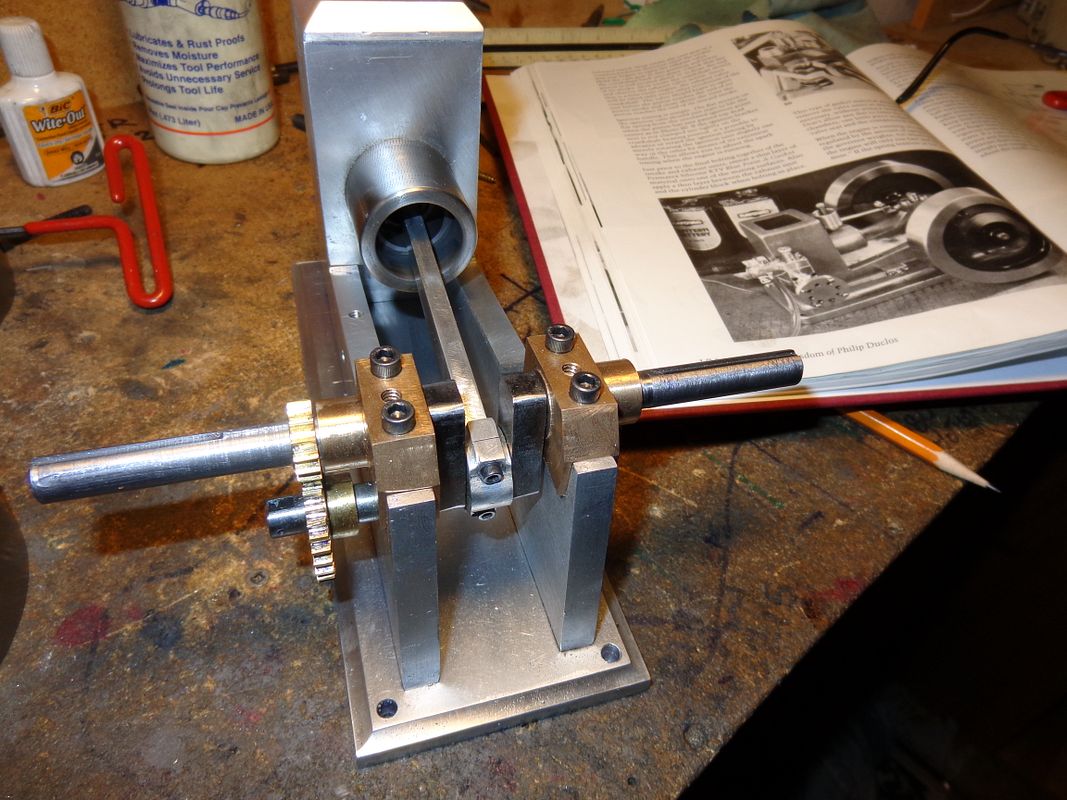
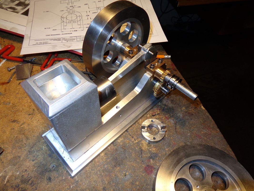
Philip Duclos "Odds N Ends" hit and miss engine

Home Model Engine Machinist Forum

Help Support Home Model Engine Machinist Forum:

This site may earn a commission from merchant affiliate links, including eBay, Amazon, and others.
Keep up the great work Steve!! Looking better all the time... I want to build one of these in the worst kind of way but im going to wait till i see how difficult the centrifugal thing is that keeps the valve/valves open before I lose all hopes that I could ever build one...lol...Great work ...Bill
 
Brian, depending on which Loctite you are using, I don't think you really need a very snug fit. Those big flywheels ought to really make it run slow and smooth.

Chuck
 
Hi Brian

A nerve racking job I know, I turned my crank from 17-4 Stainless and used a 3 jaw chuck chucked in my 4 jaw to get the offset.

Draw-Tech

3 Crank.jpg


DSCN0091.jpg
 
My appologies Brian. I was in the right thread, but i called you by the wrong name. Late night and i was trying to skim thru all the threads real fast.Sorry good sir..Bill
 
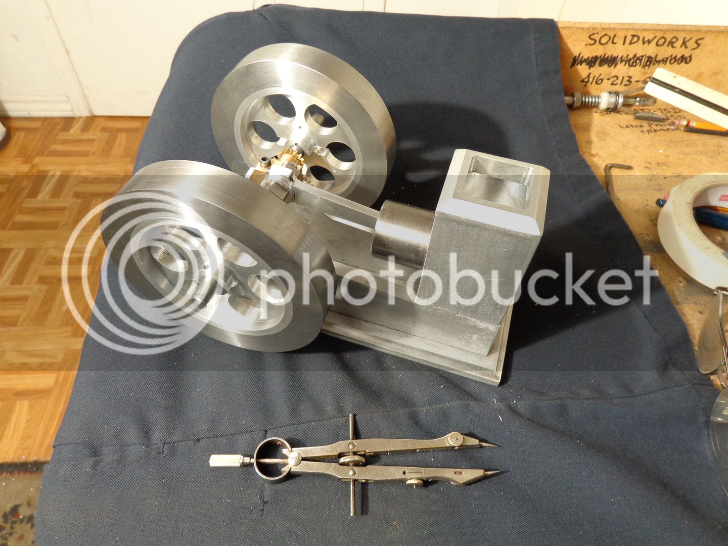
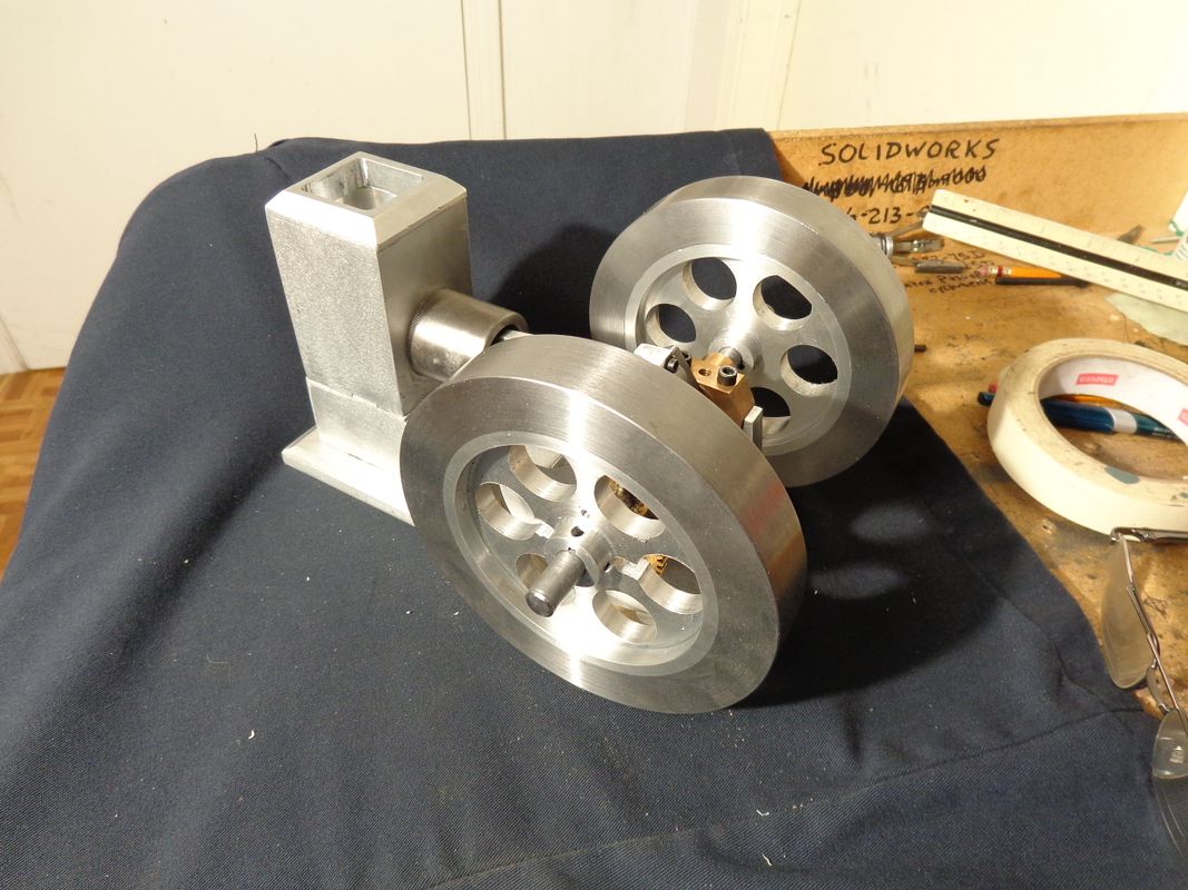
Both flywheels are finished. A ton of work, but they run true and look quite good. The mild steel mechanical tubing is 1018/1020 and is miserable stuff to get a good finish on at that large diameter in my relatively small lathe. However, 180 grit followed by 220 grit emery paper can remove a lot of surface sins. My plan all along has been to paint these flywheels when finished, as the outer rims will eventually rust from humidity in the air if left untreated.My next step will probably be to cut keyways in both ends of the crankshaft.
FLYWHEELSWITHRIMSFINISHED001_zps719b217c.jpg

FLYWHEELSWITHRIMSFINISHED002_zps326a6d30.jpg
 
Hi Brian
Coming along well, Your on the home streach Now :)
Pete
 
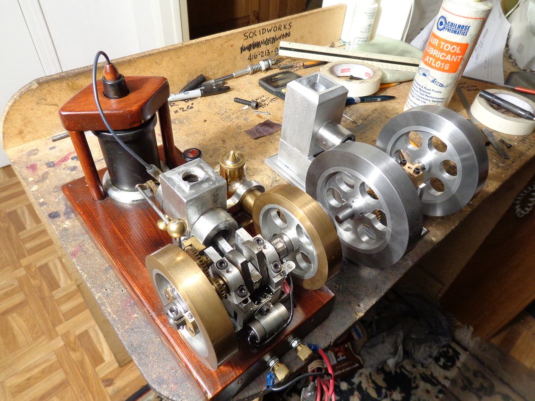
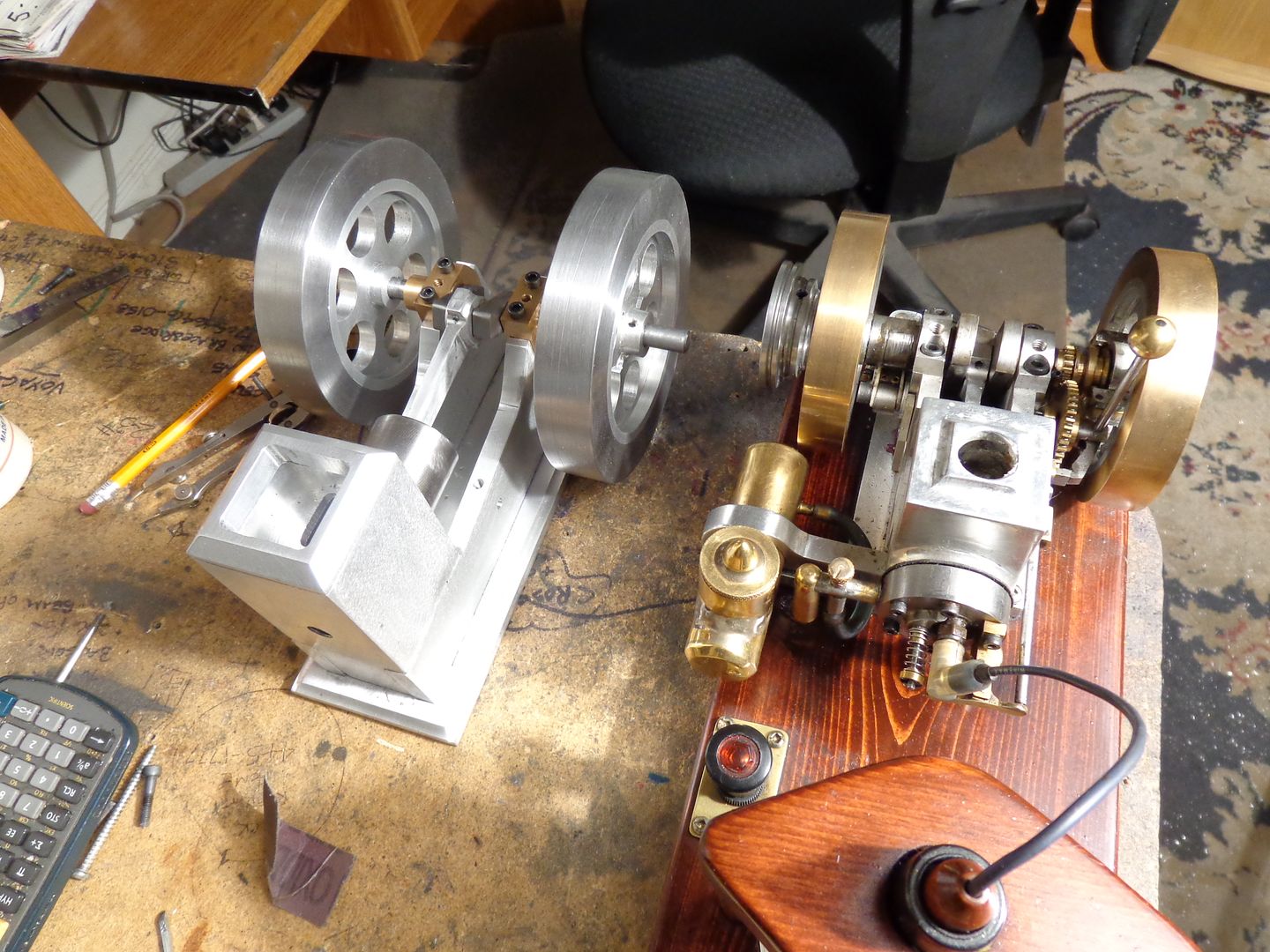
Here is an interesting comparison shot of the Odds and Ends hit and miss engine compared to the Kerzel hit and miss engine. I built the Kerzel 3 years ago, and it has a 3/4" bore and a 0.8" stroke. The Odds and Ends engine has a 1" bore and a 1 3/8" stroke. The Kerzel has 3 1/2" diameter flywheels, while the Odds and Ends engine has 5" diameter flywheels. There is a big visual difference when you see the two engines side by side.
http://www.homemodelenginemachinist.com/f31/brian-builds-kerzel-hit-miss-i-c-10091/
KERZELCOMPARISON001_zps5ea0f055.jpg

KERZELCOMPARISON002_zpsc3e0a4fc.jpg
 
Hi Brian
Coming along well, Your on the home streach Now :)
Pete
Thanks for having a look mate!!! I check out you V8 project every time you post, and your work impresses me greatly. The only casting I have ever done was working with castable resins, about 40 years ago, making car club plaques.
 
Today I am in "recovery mode" from the great flywheel thrash. I have been warned by goodwife to not get all dirty running those "machines in the basement", as we have to attend a birthday party this afternoon for an old friend who just turned 100 years old. Being the sort of guy who can take a hint, I've ran no machines today!!! I have spent the morning doing up the carburetor/exhaust/valve body for this engine in 3D cad. This helps me to figure out what I am going to do next, and gives me a better understanding of how it all fits together.------and keeps goodwife happy.--Don't get very dirty doing cad work.
ASSEMBLY-ODDSNENDS-WITHCARB_zps1fb01dbb.jpg
 
In keeping with my theme of doing at least one thing each day, I came home from the birthday party and did-----one thing!!! I machined the keyways into the crankshaft. This sounds easy, but the problem is, "How the heck do you hold something like this??" You have to hang onto one end in the vice, and machine the other end which sticks out what seems like a mile, unsupported. I don't use an endmill for keycutting. I use a woodruff key cutter, which gives a much more accurate keyway. On the first keyway, I backed up the shaft with an angle plate opposite the cutter to help curb the sideways deflection. This created some problems of its own, so the other end was cut while just sticking out into space. It did deflect a little bit, but I just took 3 or 4 "spring cuts" when I had reached the depth I wanted, and when it quit cutting I was done. They turned out good, and I have already fitted the flywheels and stuck a piece of 3/32 square key in to make sure I had cut deep enough, and its okay. How was the 100 year old guy at the birthday party??--Physically, great!!! Mentally---not so much. He was very pleased to have everyone attend his party, posed for about a thousand pictures, and got a speech from the reeve and a letter from the prime minister. I'm not sure he really recognized anyone there, but he had a great time.
KEYWAYSINCRANK-2001_zps90a2f776.jpg
 
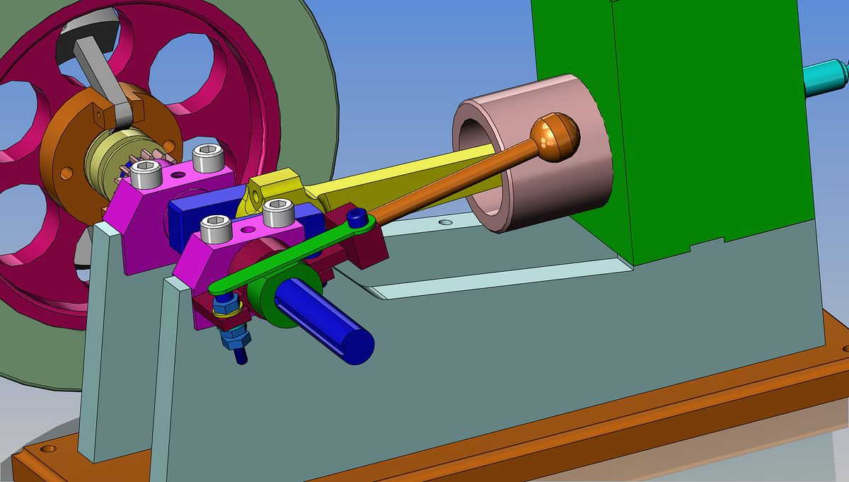
This engine has a rather interesting fabricated ignition point set up on it. It is attached with a clamp bolt to the extended hub of one of the crankshaft bearings. It has an extended handle on it, and by rotating the handle (and consequently the entire bracket) you can alter the ignition timing while the engine is running.---as long as the clamp bolt isn't clamped too tightly. I'm not sure whether this is a good feature, a bad feature, or just a unique feature that doesn't do that much, but its interesting, and I haven't seen that before.---Brian
ASSEMBLY-ODDSNENDS-IGNITIONPOINTS_zps14e3c3ca.jpg
 
When I made this engine, I made the points similar to the drawing. Takes alot of time but sure is a nice feature. I did make one change and that was soldering points from a set of auto points:D to the contacts.
 
Today was one of those "bits and pieces" days. Hiding just inboard from the one mounted flywheel is the ignition cam. At the other end of the crankshaft you can see the sliding spool that the governor arms move back and forth, and laying on the bench next to the other unmounted flywheel is the bracket from which the governor arms pivot. I managed to fit these parts in between taking goodwife out to lunch and having granddaughters over for a sleep-over tonight. The youngest granddaughter shows a lot of promise---she comes down to Poppa's machine shop and wants to know what the different machines are and what they do. The older granddaughter is far more interested in helping grandma in the kitchen.
BITSANDPIECES001_zps672093ed.jpg
 
It's fun having the grandkids in the shop (sometimes). I let my 7 year old grandson turn the cranks on the milling machine while watching the DRO. It's how I taught him about numbers when he was only 5. I also let him polish pieces on the lathe using sanding boards, under very close supervision.

Of course, I make sure he is wearing ear protection and full goggles. At his height his eyes are right inline with the swarf and other flying objects. Today I don't even have to remind him and he will yell at me if I turn the machine on before he feels he is completely ready.

Pat
 
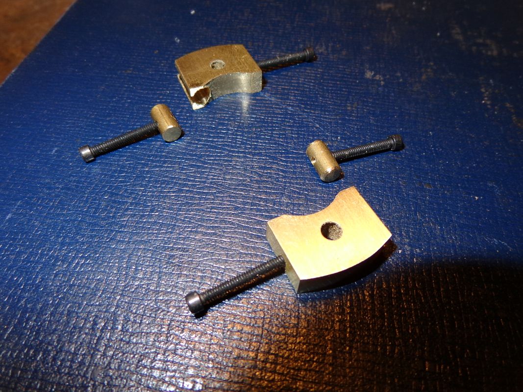
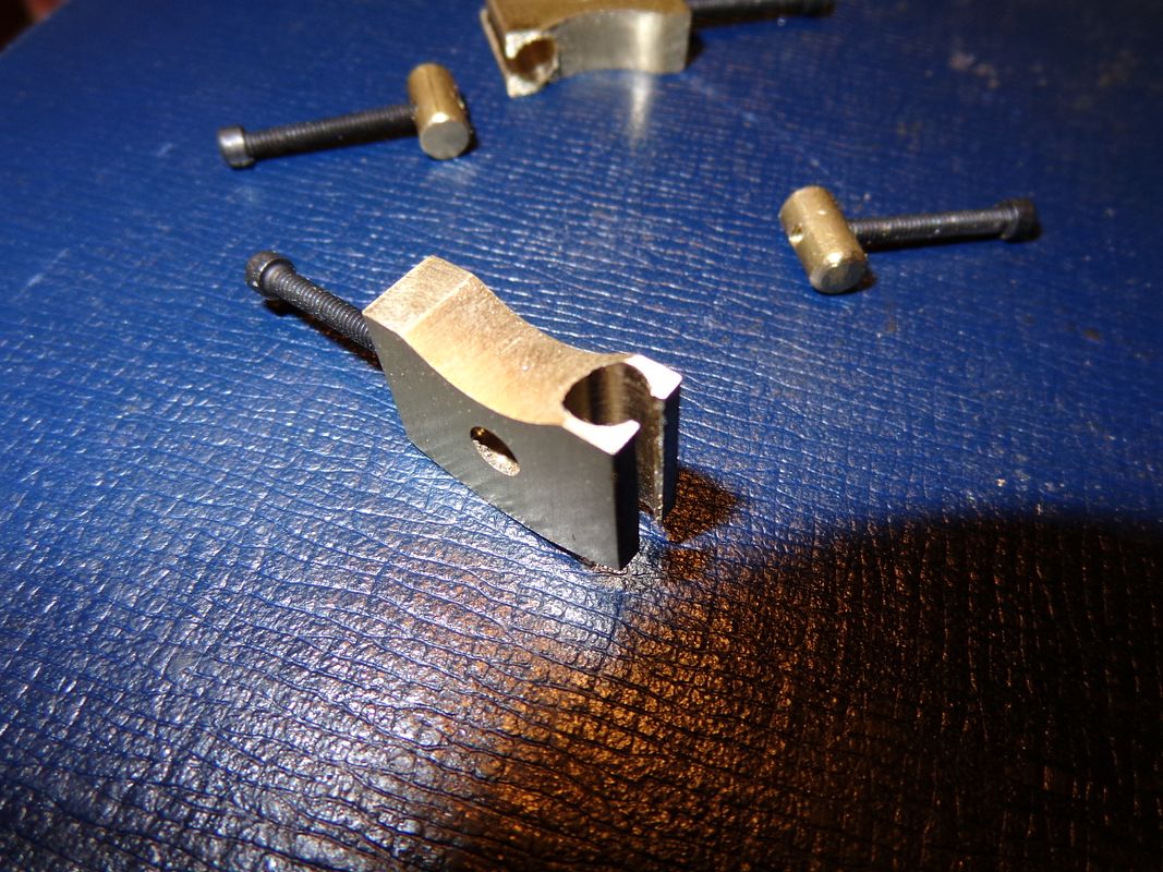
Four little parts made today. These are the weights for the centrifugal governor. However, don't let the little size fool you. There is still a lot of work there. This is one of the times I would have liked to speak with Philip Duclos and ask him why he made such a simple thing so complicated. Maybe its just the difference in machine designers, but I would simply have tapped each side of the weights for a #2-56 screw, instead of the sliding rod design that he has. Those screws anchor the tension springs between the governor weights. At any rate, his drawings are accurate and easy to follow. I redraw them anyways, because he dimensioned everything in 64ths, 32nds, and 16ths. It s hard to find those fractions on any of my equipment, so by redrawing them they get converted to decimals, which I can work with.
GOVERNORWEIGHTS001_zps8e1401e4.jpg

GOVERNORWEIGHTS002_zpsfaf80d51.jpg
 
I found those little sliding adjustments on the governor weights to be a waste of effort. It's just as easy to stretch or cut off the spring as required to get the right speed. I wound up just using one spring to get the engine to run as slow as possible without the spring being so loose it flies off from centrifugal force.

Chuck
 
This engine has a rather interesting fabricated ignition point set up on it. It is attached with a clamp bolt to the extended hub of one of the crankshaft bearings. It has an extended handle on it, and by rotating the handle (and consequently the entire bracket) you can alter the ignition timing while the engine is running.---as long as the clamp bolt isn't clamped too tightly. I'm not sure whether this is a good feature, a bad feature, or just a unique feature that doesn't do that much, but its interesting, and I haven't seen that before.---Brian

Metal Butcher used a similar setup to make an adjustable hall sensor for his Upshur engines, and I imagine it's a good idea (so I'm stealing it for my Upshurs as well :p).
If I've done this right this link should get you to the post I was talking about - number 238 on page 24 if I've done it wrong..

Not sure if I've said it already, but I'm loving this build and finding lots of inspiration to get on with mine Thm:.
 
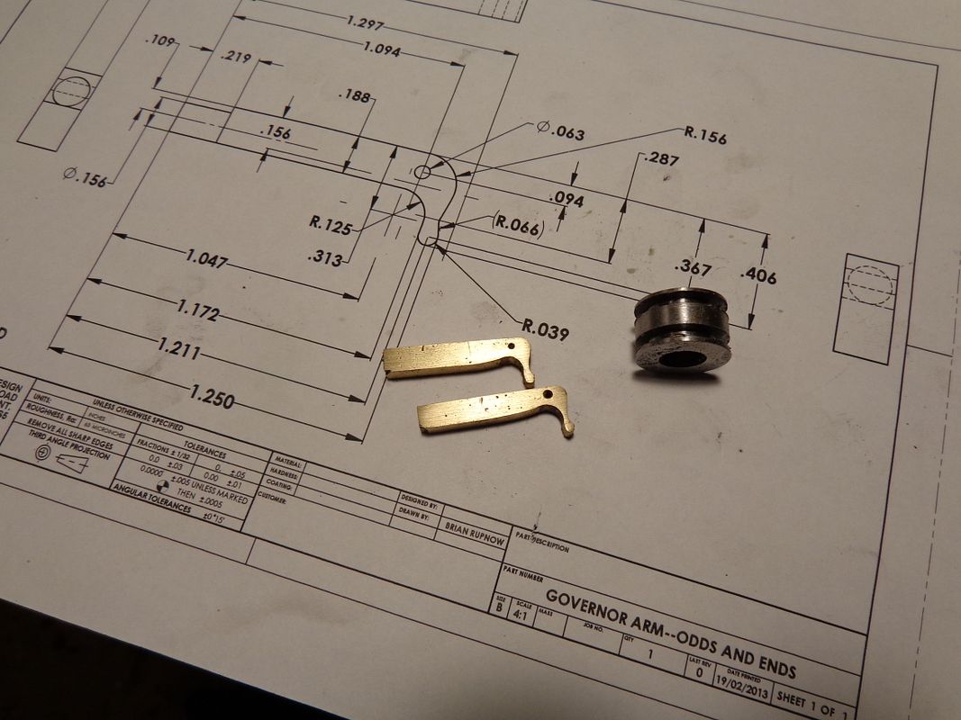
These are the little guys that always give me heart spasms. They are the arms for the centrifugal governor, and they are so small that they are hard to see, let alone work on. You can only get them "close" using conventional machining techniques. Then it is fit and file and emery cloth untill they free up and work in tandem with all the other parts. These are still not finished. They require a bit of 4 jaw work in the lathe, then get soldered to the weights in the previous post.
GOVERNORARMS001_zpsee852aeb.jpg
 
Back
Top